Trusted Business
Verified & Licensed
Virus Free Files
100% Safe Downloads
Secure Payment
SSL Protected
Instant Delivery
Available Immediately
Massey Ferguson MF 5400 Tractor Repair & Parts Manual – PDF
$40.95
Massey Ferguson MF 5400 Tractor Repair & Parts Manual – PDF DOWNLOAD
Instant PDF Download
Available immediately
Save to Your Device
Download & keep forever
Antivirus Scanned
100% virus-free
Trusted Worldwide
175,000+ customers
Description
Massey Ferguson MF 5400 Tractor Repair & Parts Manual – PDF DOWNLOAD
FILE DETAILS:
Massey Ferguson MF 5400 Tractor Repair & Parts Manual – PDF DOWNLOAD
Language : English
Pages : 2110
Downloadable : Yes
File Type : PDF
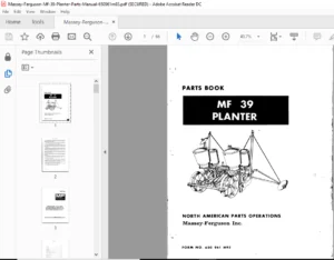
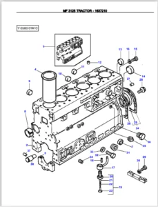
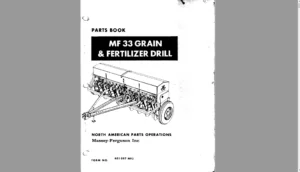
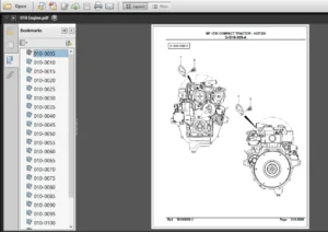
IMAGES PREVIEW OF THE MANUAL:
TABLE OF CONTENTS:
Massey Ferguson MF 5400 Tractor Repair & Parts Manual – PDF DOWNLOAD
Contents.........................................................................................................   0
01 - Introduction - Specifications...............................................................................   0
	1A10 - Using the manual......................................................................................   0
		A . General..............................................................................................   0
		B . Structure of the manual..............................................................................   0
		C . Service tools........................................................................................   0
		D . Repairs and parts replacement........................................................................   0
	1B10 - SPECIFICATIONS - General specifications...............................................................   0
		A . General specifications...............................................................................   0
	1B11 - SPECIFICATIONS - Forward speeds.......................................................................   0
		A . Speedshift models....................................................................................   0
		B . Dyna 4 models........................................................................................   0
	1B12 - SPECIFICATIONS - Dimensions...........................................................................   0
		A . General dimensions and attachment points for Speedshift models.......................................   0
		B . General dimensions and attachment points for Dyna 4 models...........................................   0
		C . Adjusting track widths...............................................................................   0
	1B13 - SPECIFICATIONS - Capacities...........................................................................   0
		A . Capacities: GBA20 Speedshift models..................................................................   0
		B . Capacities: GBA25 Dyna 4 models......................................................................   0
	1C10 - Miscellaneous.........................................................................................   0
		A . Conversion tables....................................................................................   0
		B . Retaining compounds and sealing products.............................................................   0
02 - Splitting the tractor.......................................................................................   0
03 - Engine......................................................................................................   0
04 - Clutch......................................................................................................   0
05 - Gearbox.....................................................................................................   0
06 - Rear axle...................................................................................................   0
07 - Power take off..............................................................................................   0
08 - Front axle..................................................................................................   0
09 - Hydraulics..................................................................................................   0
10 - Electrical equipment........................................................................................   0
11 - Electronics.................................................................................................   0
12 - Cab and equipment...........................................................................................   0
Contents.........................................................................................................   0
01 - Introduction - Specifications...............................................................................   0
02 - Splitting the tractor.......................................................................................   0
	2A10 - Splitting - Front frame / Perkins engine..............................................................   0
		A . General..............................................................................................   0
		B . Disassembly and reassembly (6-cylinder Perkins engine)...............................................   0
		C . Disassembly and reassembly (4-cylinder Perkins engine)...............................................   0
		D . Shimming the front frame (4-cylinder Perkins engine).................................................   0
	2B11 - Splitting Perkins engine / GTA2020....................................................................   0
		A . General..............................................................................................   0
		B . Disassembly and reassembly (Perkins 4-cylinder engine)...............................................   0
		C . Replacing the input shaft seal (tractors with dry clutch)............................................   0
		D . Disassembly and reassembly (6-cylinder Perkins engine)...............................................   0
		E . Service tool.........................................................................................   0
	2C11 - Splitting GBA20/GPA20 (cab fixed to centre housing)...................................................   0
		A . General..............................................................................................   0
		B . Disassembly and reassembly with the cab fixed to the centre housing..................................   0
	2C13 - Splitting GBA20/GPA20 (cab fixed to gearbox)..........................................................   0
		A . General..............................................................................................   0
		B . Disassembly and reassembly with the cab fixed to the gearbox.........................................   0
03 - Engine......................................................................................................   0
04 - Clutch......................................................................................................   0
05 - Gearbox.....................................................................................................   0
06 - Rear axle...................................................................................................   0
07 - Power take off..............................................................................................   0
08 - Front axle..................................................................................................   0
09 - Hydraulics..................................................................................................   0
10 - Electrical equipment........................................................................................   0
11 - Electronics.................................................................................................   0
12 - Cab and equipment...........................................................................................   0
Contents.........................................................................................................   0
01 - Introduction - Specifications...............................................................................   0
02 - Splitting the tractor.......................................................................................   0
03 - Engine......................................................................................................   0
	3A10 - Perkins engine - General..............................................................................   0
		A . Introduction.........................................................................................   0
		B . Specifications and standards relating to fuel, oil and coolant.......................................   0
		C . Main specifications..................................................................................   0
	3A11 - Perkins engine - Disassembling and reassembling.......................................................   0
		A . General..............................................................................................   0
		B . Removing and refitting adjacent components (4-cylinder engine).......................................   0
		C . Timing the engine at Top Dead Centre on the first cylinder (4-cylinder engine).......................   0
		D . Removing the injection pump (4-cylinder engine)......................................................   0
		E . Refitting the injection pump (4-cylinder engine).....................................................   0
		F . Removing and refitting adjacent components (6-cylinder engine).......................................   0
		G . Timing the engine (6-cylinder engine)................................................................   0
		H . Removing the injection pump (6-cylinder engine)......................................................   0
		I . Refitting the injection pump (6-cylinder engine).....................................................   0
		J . Service tools........................................................................................   0
	3B10 - SISU engine - General.................................................................................   0
		A . Introduction.........................................................................................   0
		B . Specifications and standards relating to fuel, oil and coolant.......................................   0
		C . Main specifications..................................................................................   0
04 - Clutch......................................................................................................   0
05 - Gearbox.....................................................................................................   0
06 - Rear axle...................................................................................................   0
07 - Power take off..............................................................................................   0
08 - Front axle..................................................................................................   0
09 - Hydraulics..................................................................................................   0
10 - Electrical equipment........................................................................................   0
11 - Electronics.................................................................................................   0
12 - Cab and equipment...........................................................................................   0
Contents.........................................................................................................   0
01 - Introduction - Specifications...............................................................................   0
02 - Splitting the tractor.......................................................................................   0
03 - Engine......................................................................................................   0
04 - Clutch......................................................................................................   0
	4A10 - GBA20 - DRY CLUTCH - Disassembling and reassembling................................................... 177
		A . General..............................................................................................   0
		B . Operation............................................................................................ 184
		C . Removing and refitting the diaphragm mechanism and friction disc..................................... 185
		D . Replacing the clutch thrust bearing.................................................................. 187
		E . Removing and refitting the hydraulic slave device assembly........................................... 190
		F . Replacing the guide rings and piston seals of the hydraulic slave device assembly.................... 192
		G . Service tool......................................................................................... 197
	4A11 - GBA20 - DRY CLUTCH - Bleeding......................................................................... 199
		A . General.............................................................................................. 201
		B . Preliminary steps.................................................................................... 201
		C . Bleeding the clutch system........................................................................... 202
05 - Gearbox.....................................................................................................   0
06 - Rear axle...................................................................................................   0
07 - Power take off..............................................................................................   0
08 - Front axle..................................................................................................   0
09 - Hydraulics..................................................................................................   0
10 - Electrical equipment........................................................................................   0
11 - Electronics.................................................................................................   0
12 - Cab and equipment...........................................................................................   0
Contents.........................................................................................................   0
01 - Introduction - Specifications...............................................................................   0
02 - Splitting the tractor.......................................................................................   0
03 - Engine......................................................................................................   0
04 - Clutch......................................................................................................   0
05 - Gearbox.....................................................................................................   0
	5A10 - GBA20 - Mechanical reverse shuttle - General - Operation..............................................   0
		A . General..............................................................................................   0
		B . Construction and description.........................................................................   0
		C . Operation............................................................................................   0
		D . Specifications of the GBA20 transmission assembly with mechanical reverse shuttle....................   0
	5A11 - GBA20 - Mechanical reverse shuttle - Input unit.......................................................   0
		A . General..............................................................................................   0
		B . Removing and refitting the input unit................................................................   0
		C . Service tools........................................................................................   0
	5A12 - GBA20 - Mechanical reverse shuttle - Shuttle..........................................................   0
		A . General..............................................................................................   0
		B . Operation............................................................................................   0
		C . Preliminary steps....................................................................................   0
		D . Disassembling and reassembling the reverse shuttle...................................................   0
		E . Shimming the secondary shaft.........................................................................   0
		F . Final steps..........................................................................................   0
	5A13 - GBA20 - Mechanical reverse shuttle - Speedshift.......................................................   0
		A . General..............................................................................................   0
		B . Operation............................................................................................   0
		C . Preliminary steps....................................................................................   0
		D . Removing and disassembling the front cover plate.....................................................   0
		E . Removing, splitting and disassembling the planet carrier assembly....................................   0
		F . Disassembling the hydraulic cover plate..............................................................   0
		G . Reassembling the planet carrier......................................................................   0
		H . Refitting the hydraulic cover plate..................................................................   0
		I . Assembling the planet carrier........................................................................   0
		J . Assembling and refitting the front cover plate.......................................................   0
		K . Extracting and replacing the primary shaft needle roller bearing.....................................   0
		L . Final steps..........................................................................................   0
	5A14 - GBA20 - Mechanical reverse shuttle - Selector cover plate............................................. 269
		A . General..............................................................................................   0
		B . Operation............................................................................................   0
		C . Removing and refitting the cover plate...............................................................   0
		D . Disassembling and reassembling the gear selector and reverse shuttle mechanisms......................   0
		E . Assembling and adjusting the gear linkage and reverse shuttle control cables.........................   0
	5A15 - GBA20 - Mechanical reverse shuttle - Selector rails...................................................   0
		A . General..............................................................................................   0
		B . Maintenance guide....................................................................................   0
		C . Creeper gear fork....................................................................................   0
		D . Hare / Tortoise fork and lock- 1st / 2nd - 3rd / 4th fork assembly and selector rail.................   0
		E . Mechanical reverse shuttle selector - Fork and selector rail.........................................   0
		F . Service tools........................................................................................   0
	5A16 - GBA20 - Mechanical reverse shuttle - Output shaft.....................................................   0
		A . General..............................................................................................   0
		B . Preliminary steps....................................................................................   0
		C . Disassembling and reassembling the selector rail and the forks.......................................   0
		D . Disassembling, reassembling and shimming the shaft...................................................   0
		E . Final steps..........................................................................................   0
	5A17 - GBA20 - Mechanical reverse shuttle - Layshaft.........................................................   0
		A . General..............................................................................................   0
		B . Preliminary steps....................................................................................   0
		C . Disassembling and reassembling the shaft.............................................................   0
		D . Final steps..........................................................................................   0
		E . Service tools........................................................................................   0
	5A18 - GBA20 - Mechanical reverse shuttle - Intermediate shaft...............................................   0
		A . General..............................................................................................   0
		B . Preliminary steps....................................................................................   0
		C . Removing and refitting the shaft and gear assembly...................................................   0
		D . Removing and refitting the gears.....................................................................   0
		E . Replacing the tapered roller bearings of the intermediate shaft......................................   0
		F . Shimming the gears...................................................................................   0
		G . Shimming the shaft...................................................................................   0
		H . Final steps..........................................................................................   0
		I . Service tool.........................................................................................   0
	5B10 - GBA20 - Power Shuttle - General - Operation...........................................................   0
		A . General..............................................................................................   0
		B . Construction and description.........................................................................   0
		C . Operation............................................................................................   0
		D . Specifications of the GBA20 transmission assembly with Power Shuttle.................................   0
	5B11 - GBA20 - Power Shuttle - Input unit....................................................................   0
		A . General..............................................................................................   0
		B . Preliminary steps....................................................................................   0
		C . Removal..............................................................................................   0
		D . Refitting............................................................................................   0
		E . Adjusting the potentiometer sensor...................................................................   0
		F . Final steps..........................................................................................   0
		G . Service tools........................................................................................   0
	5B12 - GBA20 - Power Shuttle - Shuttle.......................................................................   0
		A . General..............................................................................................   0
		B . Removing and refitting the forward clutch............................................................   0
		C . Disassembling and reassembling the forward clutch....................................................   0
		D . Shimming the forward clutch..........................................................................   0
		E . Disassembling and reassembling the reverse clutch....................................................   0
		F . Disassembling and reassembling the driving gear and shimming the shaft...............................   0
		G . Service tools........................................................................................   0
	5B13 - GBA20 - Power Shuttle - Speedshift....................................................................   0
		A . General..............................................................................................   0
		B . Operation............................................................................................   0
		C . Preliminary steps....................................................................................   0
		D . Removing and disassembling the front cover plate.....................................................   0
		E . Removing, splitting and disassembling the planet carrier assembly....................................   0
		F . Disassembling the hydraulic cover plate..............................................................   0
		G . Reassembling the planet carrier......................................................................   0
		H . Refitting the hydraulic cover plate..................................................................   0
		I . Assembling the planet carrier........................................................................   0
		J . Assembling and refitting the front cover plate.......................................................   0
		K . Final steps..........................................................................................   0
	5B14 - GBA20 - Power Shuttle - Selector cover plate..........................................................   0
		A . General..............................................................................................   0
		B . Operation............................................................................................   0
		C . Removing and refitting the cover plate...............................................................   0
		D . Disassembling and reassembling the selector mechanisms...............................................   0
		E . Fitting and adjusting the gear linkage...............................................................   0
	5B15 - GBA20 - Power Shuttle - Selector rails................................................................   0
		A . General..............................................................................................   0
		B . Maintenance guide....................................................................................   0
		C . Creeper gear fork....................................................................................   0
		D . Hare / Tortoise fork and lock- 1st / 2nd - 3rd / 4th fork assembly and selector rail.................   0
		E . Service tools........................................................................................   0
	5B16 - GBA20 - Power Shuttle - Output shaft..................................................................   0
		A . General..............................................................................................   0
		B . Preliminary steps....................................................................................   0
		C . Disassembling and reassembling the selector rail and the forks.......................................   0
		D . Disassembling, reassembling and shimming the shaft...................................................   0
		E . Final steps..........................................................................................   0
	5B17 - GBA20 - Power Shuttle - Layshaft......................................................................   0
		A . General..............................................................................................   0
		B . Preliminary steps....................................................................................   0
		C . Disassembling and reassembling the shaft.............................................................   0
		D . Final steps..........................................................................................   0
		E . Service tools........................................................................................   0
	5B18 - GBA20 - Power Shuttle - Intermediate shaft............................................................   0
		A . General..............................................................................................   0
		B . Preliminary steps....................................................................................   0
		C . Removing and refitting the shaft and gear assembly...................................................   0
		D . Removing and refitting the gears.....................................................................   0
		E . Replacing the tapered roller bearings of the intermediate shaft......................................   0
		F . Shimming the gears...................................................................................   0
		G . Shimming the shaft...................................................................................   0
		H . Final steps..........................................................................................   0
		I . Service tool.........................................................................................   0
	5C10 - GBA25 - General - Operation...........................................................................   0
		A . General..............................................................................................   0
		B . Construction and description.........................................................................   0
		C . Kinematics of the GBA25 gearbox......................................................................   0
		D . Synchronisers........................................................................................   0
		E . Main gearbox robotic control.........................................................................   0
		F . GBA25 - disassembly steps............................................................................   0
		G . Transmission GBA25 specifications....................................................................   0
	5C11 - GBA25 - PowerShuttle..................................................................................   0
		A . General..............................................................................................   0
		B . Preliminary steps....................................................................................   0
		C . Remove and reinstall the PowerShuttle................................................................   0
		D . Removing and refitting the PowerShuttle..............................................................   0
		E . Final steps..........................................................................................   0
		F . Service implements...................................................................................   0
	5C12 - GBA25 - Powershift module.............................................................................   0
		A . General..............................................................................................   0
		B . Principles of operation..............................................................................   0
		C . Kinematics...........................................................................................   0
		D . Preliminary steps....................................................................................   0
		E . Removing and refitting the Powershift module.........................................................   0
		F . Removing and refitting the Powershift module.........................................................   0
		G . Disassembling and reassembling the planetary gears...................................................   0
		H . Final steps..........................................................................................   0
		I . Service tools........................................................................................   0
	5C13 - GBA25 - Robotic mechanical gearbox....................................................................   0
		A . General..............................................................................................   0
		B . Principles of operation..............................................................................   0
		C . Description and kinematics of ratios.................................................................   0
		D . Preliminary operations...............................................................................   0
		E . Removing and refitting the primary and secondary shafts..............................................   0
		F . Disassembling and reassembling the primary and secondary shafts......................................   0
		G . Shimming the primary and secondary shafts in the housing.............................................   0
		H . Adjusting the selector rails and forks...............................................................   0
		I . Adjusting the interlock mechanism....................................................................   0
		J . Assembling the intermediate speed sensor.............................................................   0
		K . Final operations.....................................................................................   0
		L . Service tools........................................................................................   0
	5D10 - GBA20 - Creeper unit..................................................................................   0
		A . General..............................................................................................   0
		B . Operation............................................................................................   0
		C . Removing the unit and the ring gear..................................................................   0
		D . Disassembling the planet carrier.....................................................................   0
		E . Reassembling the planet carrier, refitting the ring gear and the unit................................   0
		F . Final steps..........................................................................................   0
		G . Adjusting the control................................................................................   0
	5D11 - GBA20 - Super creeper unit............................................................................   0
		A . General..............................................................................................   0
		B . Kinematics and operation.............................................................................   0
		C . Removing/refitting and disassembling/reassembling the epicyclic gear trains..........................   0
		D . Disassembling and reassembling the planet carriers...................................................   0
		E . Adjusting the control................................................................................   0
		F . General..............................................................................................   0
		G . Operation............................................................................................   0
06 - Rear axle...................................................................................................   0
07 - Power take off..............................................................................................   0
08 - Front axle..................................................................................................   0
09 - Hydraulics..................................................................................................   0
10 - Electrical equipment........................................................................................   0
11 - Electronics.................................................................................................   0
12 - Cab and equipment...........................................................................................   0
Contents.........................................................................................................   0
01 - Introduction - Specifications...............................................................................   0
02 - Splitting the tractor.......................................................................................   0
03 - Engine......................................................................................................   0
04 - Clutch......................................................................................................   0
05 - Gearbox.....................................................................................................   0
06 - Rear axle...................................................................................................   0
	6A10 - GPA20 - General - Operation...........................................................................   0
		A . General..............................................................................................   0
		B . Centre housing assembly..............................................................................   0
	6A11 - GPA20 - Normal Duty trumpet housings..................................................................   0
		A . General..............................................................................................   0
		B . Trumpet housing assembly.............................................................................   0
		C . Planet carrier.......................................................................................   0
		D . Bearings and seals...................................................................................   0
		E . Preloading the axle shaft bearings...................................................................   0
		F . Replacing the wheel stud.............................................................................   0
	6A12 - GPA20 - Heavy Duty trumpet housings...................................................................   0
		A . General..............................................................................................   0
		B . Trumpet housing assembly.............................................................................   0
		C . Planet carrier.......................................................................................   0
		D . Bearings and seals...................................................................................   0
		E . Preloading the axle shaft bearings...................................................................   0
		F . Replacing the wheel stud.............................................................................   0
	6A13 - GPA20 - Brake piston..................................................................................   0
		A . General..............................................................................................   0
		B . Disassembly..........................................................................................   0
		C . Reassembly...........................................................................................   0
	6A14 - GPA20 - Hand brake unit and control...................................................................   0
		A . General..............................................................................................   0
		B . Operation............................................................................................   0
		C . Disassembly..........................................................................................   0
		D . Reassembly...........................................................................................   0
		E . Assembling and adjusting the control.................................................................   0
	6A15 - GPA20 - Differential..................................................................................   0
		A . General..............................................................................................   0
		B . Removing the left-hand flange and differential lock assembly.........................................   0
		C . Disassembling and reassembling the differential lock assembly........................................   0
		D . Refitting the left-hand flange and the differential lock assembly....................................   0
		E . Removing the differential assembly...................................................................   0
		F . Disassembling the differential assembly and the ring gear............................................   0
		G . Removing and disassembling the pinion................................................................   0
		H . Reassembling the ring gear and the differential assembly.............................................   0
		I . Adjusting the taper distance, refitting and shimming the pinion......................................   0
		J . Refitting and shimming the differential assembly.....................................................   0
		K . Adjusting and checking the backlash..................................................................   0
		L . Service tools........................................................................................   0
	6A16 - GPA20 - Hitch and linkage.............................................................................   0
		A . General..............................................................................................   0
		B . Removal..............................................................................................   0
		C . Disassembly..........................................................................................   0
		D . Reassembly...........................................................................................   0
		E . Refitting............................................................................................   0
		F . Rear hitch...........................................................................................   0
		G . Presentation of the hitch............................................................................   0
		H . Disassembling and reassembling a lift ram............................................................   0
	6A17 - GPA20 - Auto-hitch....................................................................................   0
		A . General..............................................................................................   0
		B . Presentation of the different hitch hooks............................................................   0
		C . Adjusting the auto-hitch tie-rods and the control....................................................   0
		D . Operating principle of the Dromone retractable hitch.................................................   0
	6A18 - GPA20 - Rear wheels/hubs..............................................................................   0
		A . General..............................................................................................   0
		B . Description of rear axle wheel assembly..............................................................   0
		C . Changing the track width.............................................................................   0
		D . Replacing a wheel stud...............................................................................   0
07 - Power take off..............................................................................................   0
08 - Front axle..................................................................................................   0
09 - Hydraulics..................................................................................................   0
10 - Electrical equipment........................................................................................   0
11 - Electronics.................................................................................................   0
12 - Cab and equipment...........................................................................................   0
Contents.........................................................................................................   0
01 - Introduction - Specifications...............................................................................   0
02 - Splitting the tractor.......................................................................................   0
03 - Engine......................................................................................................   0
04 - Clutch......................................................................................................   0
05 - Gearbox.....................................................................................................   0
06 - Rear axle...................................................................................................   0
07 - Power take off..............................................................................................   0
	7A10 - GPA20 - General - Operation...........................................................................   0
		A . General..............................................................................................   0
		B . Existing power take-off types........................................................................   0
	7A11 - GPA20 - Intermediate shaft - Driving gears - Brake....................................................   0
		A . General..............................................................................................   0
		B . Operation............................................................................................   0
		C . 2-speed PTO (without shimming).......................................................................   0
		D . 2-speed PTO (with shimming)..........................................................................   0
		E . 4-speed economy PTO (without shimming)...............................................................   0
		F . 4-speed economy PTO (with shimming)..................................................................   0
		G . Assembling and adjusting the 4-speed economy PTO control.............................................   0
	7A12 - GPA20 - Removable shaft...............................................................................   0
		A . General..............................................................................................   0
		B . Replacing the 540 or 1000 rpm shaft..................................................................   0
		C . Removing and refitting the rear bearing..............................................................   0
		D . Disassembling and reassembling the rear bearing......................................................   0
		E . Disassembling and reassembling the 540 and 1000 rpm gears and the front bearing......................   0
	7A13 - GPA20 - Shiftable shaft...............................................................................   0
		A . General..............................................................................................   0
		H . Layout of components and presentation of the different versions......................................   0
		B . Removing and refitting the rear bearing..............................................................   0
		C . Disassembling and reassembling the rear bearing......................................................   0
		D . Disassembling and reassembling the 540 rpm and 1000 rpm gears and the front shaft bearing............   0
		E . Controls.............................................................................................   0
		F . Flanged shaft........................................................................................   0
		G . Shaft with reinforced sealing........................................................................   0
	7A14 - GPA20 - GSPTO.........................................................................................   0
		A . General..............................................................................................   0
		B . Operation............................................................................................   0
		C . Disassembling the power take-off (2WD version).......................................................   0
		D . Reassembling the power take-off (2WD version)........................................................   0
		E . Disassembling the power take-off (4WD version).......................................................   0
		F . Reassembling the power take-off (4WD version)........................................................   0
		G . Assembling and adjusting the control.................................................................   0
	7A15 - GPA20 - Clutch........................................................................................   0
		A . General..............................................................................................   0
		B . Operation............................................................................................   0
		C . Removing and refitting the PTO clutch (2-speed version)..............................................   0
		D . Removing and refitting the PTO clutch (4-speed version)..............................................   0
		E . Disassembling and reassembling the clutch............................................................   0
		F . Service tool.........................................................................................   0
08 - Front axle..................................................................................................   0
09 - Hydraulics..................................................................................................   0
10 - Electrical equipment........................................................................................   0
11 - Electronics.................................................................................................   0
12 - Cab and equipment...........................................................................................   0
Contents.........................................................................................................   0
01 - Introduction - Specifications...............................................................................   0
02 - Splitting the tractor.......................................................................................   0
03 - Engine......................................................................................................   0
04 - Clutch......................................................................................................   0
05 - Gearbox.....................................................................................................   0
06 - Rear axle...................................................................................................   0
07 - Power take off..............................................................................................   0
08 - Front axle.................................................................................................. 857
	8A10 - DANA - General........................................................................................ 859
		A . General description.................................................................................. 861
		B . Specifications and dimensions........................................................................ 865
		C . Product identification............................................................................... 866
	8A11 - DANA - Final drive units.............................................................................. 869
		A . General.............................................................................................. 871
		B . Description of the main components................................................................... 874
		C . Removing and refitting, disassembling and reassembling the planet carrier, sun gear and ring gear.... 875
		D . Disassembling and reassembling the wheel hub......................................................... 878
		E . Replacing a wheel stud............................................................................... 879
		F . Disassembling, reassembling and shimming the swivel housing.......................................... 879
		G . Removing and refitting the universal joint shaft..................................................... 882
		H . Service tools........................................................................................ 884
	8A12 - DANA - Differential................................................................................... 887
		A . General.............................................................................................. 889
		B . Disconnecting the front axle/frame................................................................... 893
		C . Removing the swivel housings, wheel hubs and transmissions........................................... 893
		D . Removing the drive pinion carrier.................................................................... 893
		E . Removing the differential unit....................................................................... 894
		F . Removing the ring gear - Disassembling the planet gears and sun gears................................ 895
		G . Removing the differential lock....................................................................... 896
		H . Removing the pinion.................................................................................. 896
		I . Adjusting the position - Shimming and refitting the pinion........................................... 897
		J . Refitting the differential lock...................................................................... 900
		K . Reassembling planet gears and sun gears - Refitting the ring gear.................................... 901
		L . Refitting and shimming the differential unit......................................................... 902
		M . Piston tightness test................................................................................ 903
		N . Refitting the drive pinion carrier................................................................... 904
		O . Refitting swivel housings, wheel hubs and transmissions.............................................. 904
		P . Assembling the front axle / frame.................................................................... 904
		Q . Service tools........................................................................................ 905
	8A13 - DANA - Bearing and transmission shaft................................................................. 907
		A . General.............................................................................................. 909
		B . Removing and refitting the bearings.................................................................. 913
		C . Replacing the friction rings and the seal............................................................ 915
	8A14 - 4WD GPA20 clutch...................................................................................... 917
		A . General.............................................................................................. 919
		B . Operation............................................................................................ 919
		C . Removing the clutch assembly......................................................................... 923
		D . Disassembling the clutch............................................................................. 924
		E . Reassembling the clutch.............................................................................. 925
		F . Refitting the clutch assembly........................................................................ 926
		G . Makeshift tools...................................................................................... 928
	8B10 - CARRARO - General..................................................................................... 929
		A . General description.................................................................................. 931
		B . Specifications and dimensions........................................................................ 935
		C . Product identification............................................................................... 936
	8B11 - CARRARO - Final drive units........................................................................... 939
		A . General.............................................................................................. 941
		B . Dismantling the steering ram assembly................................................................ 941
		C . Disassembling the final drive unit................................................................... 942
		D . Disassembling the wheel hub.......................................................................... 943
		E . Dismantling the axle beam assembly................................................................... 947
		F . Reassembling the axle beam assembly.................................................................. 949
		G . Reassembling the wheel hub assembly.................................................................. 950
		H . Reassembling the final drive assembly................................................................ 956
		I . Wheel alignment...................................................................................... 957
		J . Adjusting the steering angle......................................................................... 959
		K . Service tools........................................................................................ 960
	8B12 - CARRARO - Differential................................................................................ 963
		A . General.............................................................................................. 965
		B . Splitting the front axle / frame..................................................................... 965
		C . Removing the wheel hubs, axle beam assembly and steering ram......................................... 965
		D . Dismantling the differential housing assembly........................................................ 966
		E . Dismantling the pinion assembly...................................................................... 969
		F . Dismantling the differential assembly................................................................ 971
		G . Refitting the pinion assembly........................................................................ 973
		H . Reassembling the differential unit................................................................... 977
		I . Refitting the differential housing assembly.......................................................... 979
		J . Service tools........................................................................................ 985
	8B13 - CARRARO - Bearing and transmission shaft.............................................................. 989
		A . General.............................................................................................. 991
		B . Disassembling and reassembling the 4WD transmission shafts and the universal joint spiders........... 995
		C . Removing and refitting the bearing support and front axle............................................ 997
		D . Replacing the friction rings and seal................................................................1000
	8B14 - 4WD GPA20 clutch......................................................................................   0
		A . General..............................................................................................1005
		B . Operation............................................................................................1005
		C . Removing the clutch assembly.........................................................................1009
		D . Disassembling the clutch.............................................................................1010
		E . Reassembling the clutch..............................................................................1011
		F . Refitting the clutch assembly........................................................................1012
		G . Makeshift tools......................................................................................1014
	8C10 - 2WD front axle........................................................................................1015
		A . General..............................................................................................1017
		B . Disassembling and reassembling the wheel hub.........................................................1021
		C . Removing and refitting the stub axle and its support.................................................1022
		D . Disassembling and reassembling the stub axle support.................................................1023
		E . Removing and refitting the front axle................................................................1024
		F . Disassembling and reassembling the pivot bearings....................................................1025
		G . Removing and refitting the ram pivot and the steering ram............................................1027
		H . Disassembling and reassembling the steering ram......................................................1028
		I . Wheel alignment......................................................................................1030
		J . Service tools........................................................................................1031
	8D10 - 2WD front axle, 6-cylinder engine.....................................................................1035
		A . General..............................................................................................1037
		B . Removing and refitting the steering rod..............................................................1044
		C . Removing and refitting the hub, the stub axle and the telescopic arm.................................1044
		D . Removing and refitting the steering ram..............................................................1046
		E . Removing and refitting the front axle................................................................1047
		F . Wheel alignment......................................................................................1049
		G . Adjusting track widths...............................................................................1049
09 - Hydraulics..................................................................................................   0
10 - Electrical equipment........................................................................................   0
11 - Electronics.................................................................................................   0
12 - Cab and equipment...........................................................................................   0
Contents.........................................................................................................   0
01 - Introduction - Specifications...............................................................................   0
02 - Splitting the tractor.......................................................................................   0
03 - Engine......................................................................................................   0
04 - Clutch......................................................................................................   0
05 - Gearbox.....................................................................................................   0
06 - Rear axle...................................................................................................   0
07 - Power take off..............................................................................................   0
08 - Front axle..................................................................................................   0
09 - Hydraulics..................................................................................................   0
	9A10 - Description of open centre system (OC 57 l/min).......................................................1053
		A . General..............................................................................................   0
		B . Low-pressure system, low flow rate...................................................................   0
		C . Layout of the main Speedshift and Power Shuttle system components....................................   0
		D . Layout of the main Speedshift and mechanical reverse shuttle system components.......................   0
		E . High-pressure system, high flow rate.................................................................   0
		F . Mechanical reverse shuttle and Speedshift diagram....................................................   0
		G . Power Shuttle and Speedshift diagram.................................................................   0
	9A20 - Description of open centre system (OC 100 l/min)......................................................1065
		A . General..............................................................................................   0
		B . System schematic diagrams............................................................................   0
		C . Low-pressure system, low flow rate...................................................................   0
		D . High-pressure system, high flow rate.................................................................   0
		E . Pump suction system..................................................................................   0
		F . Layout of the main Speedshift and Power Shuttle system components....................................   0
		G . Layout of the main Speedshift and mechanical reverse shuttle system components.......................   0
		H . 100 l/min open centre hydraulic system diagrams......................................................   0
	9A30 - Description of Load Sensing system....................................................................1083
		A . General..............................................................................................   0
		B . Principle of the Load Sensing system.................................................................   0
		C . Lubrication system of the Dyna-4 and gearbox.........................................................   0
		D . Rear axle lubrication system.........................................................................   0
		E . Gearbox low-pressure system (20 bar).................................................................   0
		F . Layout of the main components in low and high-pressure systems.......................................   0
		G . Diagrams.............................................................................................   0
	9B10 - OC 57 l/min hydraulic tests...........................................................................   0
		A . General..............................................................................................   0
		B . High flow rate system................................................................................1100
		C . Low flow rate system.................................................................................   0
	9B20 - OC 100 l/min hydraulic tests..........................................................................   0
		A . General..............................................................................................   0
		B . High flow rate system................................................................................   0
		C . Low flow rate system.................................................................................   0
	9B30 - Load Sensing hydraulic tests..........................................................................1141
		A . General..............................................................................................   0
		B . High pressure system.................................................................................   0
		C . Low pressure system (20 bar).........................................................................   0
		D . Cooling and lubrication system.......................................................................   0
		E . Suspended front axle hydraulic tests.................................................................   0
		F . Checking the pressure of the front axle accumulators.................................................   0
		G . Bypasses used........................................................................................   0
	9C10 - Right-hand cover plate (OC 57 l/min)..................................................................1167
		A . General..............................................................................................   0
		B . Identification of channels and ports.................................................................   0
		C . Removing and refitting the cover plate...............................................................   0
		D . Disassembling and reassembling the high pressure valve...............................................   0
		E . Disassembling and reassembling the cover plate.......................................................   0
		F . Removing and refitting the pump......................................................................   0
		G . Disassembling and reassembling the pump..............................................................   0
		H . Adjusting the engine speed sensor....................................................................   0
	9C20 - Right-hand cover plate (OC 100 l/min).................................................................1187
		A . General..............................................................................................   0
		B . Removing and refitting the cover plate...............................................................   0
		C . Disassembling and reassembling the high pressure valve...............................................   0
		D . Disassembling and reassembling the cover plate.......................................................   0
		E . Removing and refitting the pump......................................................................   0
		F . Disassembling and reassembling the pump..............................................................   0
		G . Adjusting the engine speed sensor....................................................................   0
	9C30 - Load Sensing right-hand cover plate...................................................................1205
		A . General..............................................................................................   0
		B . Identification of channels and ports…................................................................   0
		C . Removing and refitting the cover plate...............................................................   0
		D . Description and operation of the variable displacement pump..........................................   0
		E . Removing and refitting the pump......................................................................   0
		F . Adjusting the engine speed sensor....................................................................   0
		G . Priority block.......................................................................................   0
	9D10 - Left-hand cover plate (OC 57 l/min)...................................................................   0
		A . General..............................................................................................   0
		B . Removing and refitting...............................................................................   0
	9D20 - Left-hand cover plate (OC 100 l/min)..................................................................   0
		A . General..............................................................................................   0
		B . Removing and refitting the cover plate...............................................................   0
		C . Disassembling and reassembling the cover plate.......................................................   0
		D . Removing and refitting the pump......................................................................   0
		E . Disassembling and reassembling the pump..............................................................   0
	9D30 - Load Sensing left-hand cover plate....................................................................   0
		A . General..............................................................................................   0
		B . Identification of channels and ports…................................................................   0
		C . Removing and refitting the cover plate...............................................................   0
		D . Removing and refitting the charge pump...............................................................   0
		E . Replacing the pump seals.............................................................................   0
	9E10 - Unassisted brake master cylinders.....................................................................   0
		A . General..............................................................................................   0
		B . Layout of hydraulic lines............................................................................   0
		C . Practical maintenance advice.........................................................................   0
		D . Single-system master cylinders (without trailer brake)...............................................   0
		E . Double-system master cylinders (with trailer brake)..................................................   0
		F . Adjusting brake pedals...............................................................................   0
		G . Bleeding the main brake system.......................................................................   0
		H . Bleeding the trailer brake system....................................................................   0
	9E11 - Assisted brake master cylinders.......................................................................   0
		A . General..............................................................................................   0
		B . Layout of hydraulic lines............................................................................   0
		C . Practical maintenance advice.........................................................................   0
		D . Brake master cylinders...............................................................................   0
		E . FTE valve............................................................................................   0
		F . Adjusting brake pedals...............................................................................   0
		G . Bleeding the main brake system.......................................................................   0
		H . Bleeding the trailer brake system....................................................................   0
	9F10 - Trailer braking - Bosch valve.........................................................................   0
		A . General..............................................................................................   0
		B . Removing and refitting the brake spool valve.........................................................   0
		C . Operation, trailer brakes released and partial braking...............................................   0
		D . Partial and maximum trailer braking..................................................................   0
		E . Version without trailer braking......................................................................   0
	9F20 - Load Sensing trailer braking..........................................................................   0
		A . General..............................................................................................   0
		B . Identification of 110 l/min Load Sensing ports.......................................................   0
		C . Spool operation......................................................................................   0
		D . Removing and refitting the braking unit..............................................................   0
		E . Plug torques in the event of maintenance on the spools (2) (6).......................................   0
	9H10 - Linkage spool valve (OC)..............................................................................   0
		A . General..............................................................................................   0
		B . Layout of components and identification of ports.....................................................   0
		C . Neutral position.....................................................................................   0
		D . Lifting position.....................................................................................   0
		E . Lowering position....................................................................................   0
		F . Security valve.......................................................................................   0
		G . Removing and refitting the spool valve...............................................................   0
	9H20 - Load Sensing linkage spool valve......................................................................1353
		A . General..............................................................................................   0
		B . Layout of components and identification of ports.....................................................   0
		C . Removing and refitting the spool valve block.........................................................   0
		D . Diagram..............................................................................................   0
		E . Neutral position.....................................................................................   0
		F . Lifting position.....................................................................................   0
		G . Lowering position....................................................................................   0
	9I10 - OC auxiliary spool valve..............................................................................   0
		A . General..............................................................................................   0
		B . Layout of channels and ports.........................................................................   0
		C . Operating and adjusting the flow divider.............................................................   0
		D . Removing and refitting spool valves..................................................................   0
		E . 3-position spool valve, SE/DE with return to neutral by spring.......................................   0
		F . 3-position spool valve, SE/DE with automatic return to neutral.......................................   0
		G . 3-position SE/DE spool valve with non-return valve and automatic return..............................   0
		H . 4-position DE spool valve, with automatic return to neutral and floating position....................   0
		I . Fitting and adjusting a control cable................................................................   0
	9I20 - Auxiliary Load Sensing spool valves...................................................................   0
		A . General..............................................................................................   0
		B . Operation............................................................................................   0
		C . Layout of components and identification of ports.....................................................   0
		D . Diagram..............................................................................................   0
		E . Spool valve assembly.................................................................................   0
		F . Assembly procedure...................................................................................   0
		G . Fitting and adjusting the control cables.............................................................   0
	9M10 - 17 bar valve..........................................................................................1401
		A . General..............................................................................................1403
		B . Description of the 17 bar low pressure valve.........................................................1405
		C . Removing and refitting, disassembling and reassembling the 17 bar valve..............................   0
		D . Adjusting the 17 bar valve...........................................................................   0
		E . Operation of the cooling system......................................................................   0
		F . Assembling the 5 bar valve...........................................................................   0
		G . Description of the 1.5 bar lubricating valve.........................................................   0
		H . Removing and refitting, disassembling and reassembling the 1.5 bar valve.............................1411
	9N10 - Power Shuttle control unit............................................................................   0
		A . General..............................................................................................   0
		B . Presentation of the control unit and hydraulic lines.................................................   0
		C . Power Shuttle control................................................................................   0
		D . Speedshift control...................................................................................1419
		E . Explanation of Speedshift ratios.....................................................................   0
		F . Removing and refitting the control unit..............................................................   0
10 - Electrical equipment........................................................................................   0
11 - Electronics.................................................................................................   0
12 - Cab and equipment...........................................................................................   0
Contents.........................................................................................................   0
01 - Introduction - Specifications...............................................................................   0
02 - Splitting the tractor.......................................................................................   0
03 - Engine......................................................................................................   0
04 - Clutch......................................................................................................   0
05 - Gearbox.....................................................................................................   0
06 - Rear axle...................................................................................................   0
07 - Power take off..............................................................................................   0
08 - Front axle..................................................................................................   0
09 - Hydraulics..................................................................................................   0
10 - Electrical equipment........................................................................................   0
	10B10 - Electrical diagrams - Cab equipment..................................................................   0
		A . General..............................................................................................   0
		B . Cab equipment........................................................................................   0
	10C10 - Electrical diagrams - Engine equipment...............................................................   0
		A . General..............................................................................................   0
		B . Engine equipment.....................................................................................   0
	10D10 - Electrical diagrams - Transmission...................................................................   0
		A . General..............................................................................................   0
		B . Transmission.........................................................................................   0
	10E10 - Electrical diagrams - Lighting.......................................................................1561
		A . General..............................................................................................   0
		B . Types of bulb........................................................................................   0
		C . Lighting.............................................................................................   0
	10F10 - Electrical diagrams - Power supply to electronic boxes...............................................   0
		A . General..............................................................................................   0
		B . Controller power supply..............................................................................   0
11 - Electronics.................................................................................................   0
12 - Cab and equipment...........................................................................................   0
Contents.........................................................................................................   0
01 - Introduction - Specifications...............................................................................   0
02 - Splitting the tractor.......................................................................................   0
03 - Engine......................................................................................................   0
04 - Clutch......................................................................................................   0
05 - Gearbox.....................................................................................................   0
06 - Rear axle...................................................................................................   0
07 - Power take off..............................................................................................   0
08 - Front axle..................................................................................................   0
09 - Hydraulics..................................................................................................   0
10 - Electrical equipment........................................................................................   0
11 - Electronics.................................................................................................1657
	GUF111 - ELECTRONIC INJECTION - Perkins - Programming........................................................   0
		A . Configuration........................................................................................   0
		B . Programming..........................................................................................   0
	GUF112 - Perkins ELECTRONIC INJECTION - Tests and diagnostics................................................   0
		A . Tests and diagnostics................................................................................   0
	GUF113 - Perkins ELECTRONIC INJECTION - Error codes..........................................................   0
		A . Reading error codes..................................................................................   0
		B . List of error codes..................................................................................   0
		C . Reaction of the system when an error code occurs.....................................................   0
		D . Reaction of the system when an error code with an event occurs.......................................   0
	GUF115 - Perkins ELECTRONIC INJECTION - Electrical Diagrams..................................................   0
		A . Perkins engine harness...............................................................................   0
		B . General Tractor with DCC2............................................................................   0
		C . Electrical diagrams for tractors with DCC2...........................................................   0
		D . General Tractor without DCC2.........................................................................   0
		E . Electrical diagrams for tractors without DCC2........................................................   0
	11B10 - AUTOTRONIC 5 - Description...........................................................................   0
		A . General..............................................................................................   0
		B . Autotronic 5 status flowcharts.......................................................................   0
		C . Autotronic 5 connector pin allocation................................................................   0
		D . Automatic responses of the Autotronic 5..............................................................   0
		E . Power Shuttle principles.............................................................................   0
	GUF511 - AUTOTRONIC 5 - Power Shuttle - Programming and setting parameters...................................   0
		A . Programming..........................................................................................   0
		B . Saving to a file.....................................................................................   0
		C . Setting parameters...................................................................................   0
	GUF512 - AUTOTRONIC 5 - Power Shuttle - Tests and diagnostics................................................   0
		A . Autotronic 5 statuses................................................................................   0
		B . Gearbox function.....................................................................................   0
		C . Power Take-Off function..............................................................................   0
	GUF513 - AUTOTRONIC 5 - Power Shuttle - Error codes..........................................................   0
		A . Reading error codes..................................................................................   0
		B . List of error codes..................................................................................   0
		C . Analysing components and their error codes...........................................................   0
		D . Analysing other error codes..........................................................................   0
	GUF514 - AUTOTRONIC 5 - Power Shuttle - Calibration and adjustments..........................................   0
		A . Calibrating the PowerShuttle.........................................................................   0
		B . Adjusting the PowerShuttle progressive shifting......................................................   0
		C . Adjusting the manoeuvring pedal......................................................................   0
		D . Calibrating the (manoeuvring) clutch pedal...........................................................   0
	GUF515 - AUTOTRONIC 5 - Power Shuttle - Electrical diagrams..................................................   0
		A . General..............................................................................................   0
		B . Electrical diagrams..................................................................................   0
		C . Layout of components.................................................................................   0
	11C10 - ELECTRONIC LINKAGE - Description.....................................................................1829
		A . Description..........................................................................................   0
		B . Console..............................................................................................   0
		C . Electronic calculator EHRB connector pin allocation..................................................   0
	11C12 - ELECTRONIC LINKAGE - Tests and diagnostics...........................................................   0
		A . Electronic Linkage component testing and diagnostics.................................................   0
	11C13 - ELECTRONIC LINKAGE - Error codes.....................................................................   0
		A . Reading error codes..................................................................................   0
		B . List of error codes..................................................................................   0
		C . Analysing components and their error codes...........................................................   0
	11C14 - ELECTRONIC LINKAGE - Adjustment......................................................................   0
		A . Adjusting the position sensor........................................................................   0
	11C15 - ELECTRONIC LINKAGE - Electrical diagrams.............................................................   0
		A . General..............................................................................................   0
		B . Electrical diagrams..................................................................................   0
	11C20 - Autotronic 5 - Linkage - Description.................................................................1879
		A . Description..........................................................................................   0
		B . Console..............................................................................................   0
		C . Autotronic 5 calculator connector....................................................................   0
	GUF521 - AUTOTRONIC 5 - Linkage - Programming and setting parameters.........................................   0
		A . Programming..........................................................................................   0
		B . Saving to a file.....................................................................................   0
		C . Setting parameters...................................................................................   0
		D . Table of constants...................................................................................   0
	GUF522 - AUTOTRONIC 5 - Linkage - Tests and diagnostics - MF5400.............................................   0
		A . Autotronic 5 statuses................................................................................   0
		B . Electronic Linkage functions.........................................................................   0
	GUF523 - AUTOTRONIC 5 - Linkage - Error codes - MF5400.......................................................   0
		A . Reading error codes..................................................................................   0
		B . List of error codes..................................................................................   0
		C . Analysing components and their error codes...........................................................   0
	GUF524 - AUTOTRONIC 5 - Linkage - Calibration and adjustments................................................   0
		A . Adjusting the position sensor........................................................................   0
		B . Calibrating the linkage..............................................................................   0
	GUF525 - AUTOTRONIC 5 - Linkage - Electrical diagrams - MF5400...............................................   0
		A . General..............................................................................................   0
		B . Electrical diagrams..................................................................................   0
	11D10 - AUTOTRONIC 5 - Dyna-4 - Description..................................................................   0
		A . General..............................................................................................   0
		B . Components description...............................................................................   0
		C . Creeper function.....................................................................................   0
		D . 4 WD function........................................................................................   0
		E . Differential lock function...........................................................................   0
		F . Power take-off function..............................................................................   0
		G . PowerShuttle function................................................................................   0
		H . Transmission function................................................................................   0
		I . Allocation of Autotronic 5 transmission controller pins..............................................   0
	GUF571 - AUTOTRONIC 5 - Dyna-4 - Programming and setting parameters..........................................   0
		A . Programming..........................................................................................   0
		B . Saving to a file.....................................................................................   0
		C . Setting parameters...................................................................................   0
	GUF573 - AUTOTRONIC 5 - Dyna-4 - Error codes.................................................................   0
		A . Reading error codes..................................................................................   0
		B . List of error codes..................................................................................   0
		C . Analysing components and their error codes...........................................................   0
		D . Analysing other error codes..........................................................................   0
	GUF574 - AUTOTRONIC 5 - Dyna-4 - Calibration.................................................................   0
		A . Power Shuttle calibration............................................................................   0
		B . Adjusting the clutch (manoeuvring) pedal.............................................................   0
	GUF575 - AUTOTRONIC 5 - Dyna-4 - Electrical diagrams.........................................................   0
		A . General..............................................................................................   0
		B . Electrical diagrams..................................................................................   0
12 - Cab and equipment...........................................................................................   0
Contents.........................................................................................................   0
01 - Introduction - Specifications...............................................................................   0
02 - Splitting the tractor.......................................................................................   0
03 - Engine......................................................................................................   0
04 - Clutch......................................................................................................   0
05 - Gearbox.....................................................................................................   0
06 - Rear axle...................................................................................................   0
07 - Power take off..............................................................................................   0
08 - Front axle..................................................................................................   0
09 - Hydraulics..................................................................................................   0
10 - Electrical equipment........................................................................................   0
11 - Electronics.................................................................................................   0
12 - Cab and equipment...........................................................................................   0
	12B10 - Air conditioning - General...........................................................................2075
		A . General..............................................................................................2077
		B . Schematic diagram....................................................................................2079
		C . Technical specifications.............................................................................2081
		D . Safety instructions..................................................................................2083
		E . General maintenance..................................................................................2084
		F . System troubleshooting...............................................................................2084
	12B11 - Air conditioning - Standard..........................................................................2089
		A . General..............................................................................................2091
		B . Electrical diagram...................................................................................2095
	12B12 - Air conditioning - Refilling the unit................................................................2097
		A . Draining the system and checking for leaks...........................................................2099
		B . Drafting the system and detecting leaks..............................................................2100
		C . Refilling the unit (engine stopped)..................................................................2101
		D . Checking pressures...................................................................................2103
		E . Service tools........................................................................................2104
	12D10 - Orchard cab..........................................................................................2105
		A . General..............................................................................................2107
		B . Dimensions and attachment points.....................................................................2108
DESCRIPTION:
Massey Ferguson MF 5400 Tractor Repair & Parts Manual – PDF DOWNLOAD
GENERAL:
- The purpose of this manual is to assist Dealers and Agents in the efficient installation, maintenance and repair of AGCO equipment.
- Carrying out the procedures as detailed, together with the use of special tools where appropriate, will enable the operations to be completed within the time stated in the repair time schedule.
Structure of the manual:
- Page numbering This manual is divided into chapters and sections, each page containing the following information: Example: 10A12.1 10 = chapter A12 = section 1 = page number within the section
- The issue number is indicated at the bottom of the page. Summaries For quick reference, each chapter starts with a table of contents, listing the various sections included in that chapter. Meaning of references (…): identification of parts and components
- Amendments Modified pages will be edited using the same page numbering as the preceding pages—only the issue number changes. The old pages should be destroyed
G.B 11/04/25