Massey Ferguson MF 6700S Series 6713S 6714S 6715S 6716S 6718S Dyna-6 Operator Instruction Manual – PDF DOWNLOAD
Original price was: $67.95.$24.95Current price is: $24.95.
Massey Ferguson MF 6700S Series 6713S 6714S 6715S 6716S 6718S Dyna-6 Operator Instruction Manual – PDF DOWNLOAD
Description
Massey Ferguson MF 6700S Series 6713S 6714S 6715S 6716S 6718S Dyna-6 Operator Instruction Manual – PDF DOWNLOAD
DESCRIPTION:
Massey Ferguson MF 6700S Series 6713S 6714S 6715S 6716S 6718S Dyna-6 Operator Instruction Manual – PDF DOWNLOAD
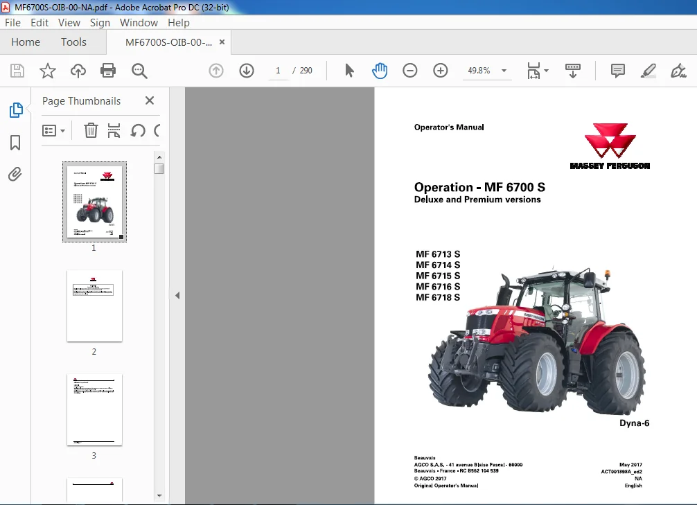
Operation – MF 6700 S
Deluxe and Premium versions
MF 6713 S
MF 6714 S
MF 6715 S
MF 6716 S
MF 6718 S
Part. No : ACT001898A_ed2
Operator’s Manual :
The purpose of this manual is to enable the owner and the operator to operate the tractor appropriately under normal conditions of use. Providing they follow the instructions carefully, the tractor will give many years of service in the Massey Ferguson tradition. Use for any other activity (particularly forestry work) is considered to be contrary to the intended use. The commissioning of equipment by the Massey Ferguson dealer on the user’s premises enables the dealer to ensure that these operating and service instructions are properly understood. Always consult the Massey Ferguson dealer it there is any part of this manual that you do not understand.
- It is Important that these instructions are understood and followed. This manual does not cover all operation and saloty instructions relevant to the implements and accessories that may be fitted at the time of tractor delivery or later. It is essential that operators use and understand the Operator’s Manuals relating to these implements and accessories.
- This chapter in the Operator’s Manual highlights certain basic safety-related Situations that may be encountered during normal operation and servicing of the tractor and provides the information needed to handle these situations. This chapter supplements any safety instructions given in other chapters of this manual.
- It may be necessary to take additional precautions. depending on tho implements and accessories used and the working conditions on-site or in the sen-ice area. Massey Ferguson can under no circumstances exercise direct control over the commissioning, operation, inspection. lubrication or servicing of the tractor. It is therefore YOUR responsibility to take suitable safety precautions in such areas.
TABLE OF CONTENTS:
Massey Ferguson MF 6700S Series 6713S 6714S 6715S 6716S 6718S Dyna-6 Operator Instruction Manual – PDF DOWNLOAD
1 Tractor identification 11
1 1 Locating serial numbers 13
1 1 1 Locating serial numbers 13
1 2 Your tractor identification details 15
1 2 1 Your tractor identification details 15
2 Safety instructions and safety points – Warranty 17
2 1 Introduction 19
2 1 1 Introduction – Safety instructions 19
2 2 Safety – Symbols and terms 21
2 2 1 Safety- Symbols and terms 2 1
2 3 Safety decals and instructions 22
2 3 1 Checking and replacing the safety decals and instructions 2 2
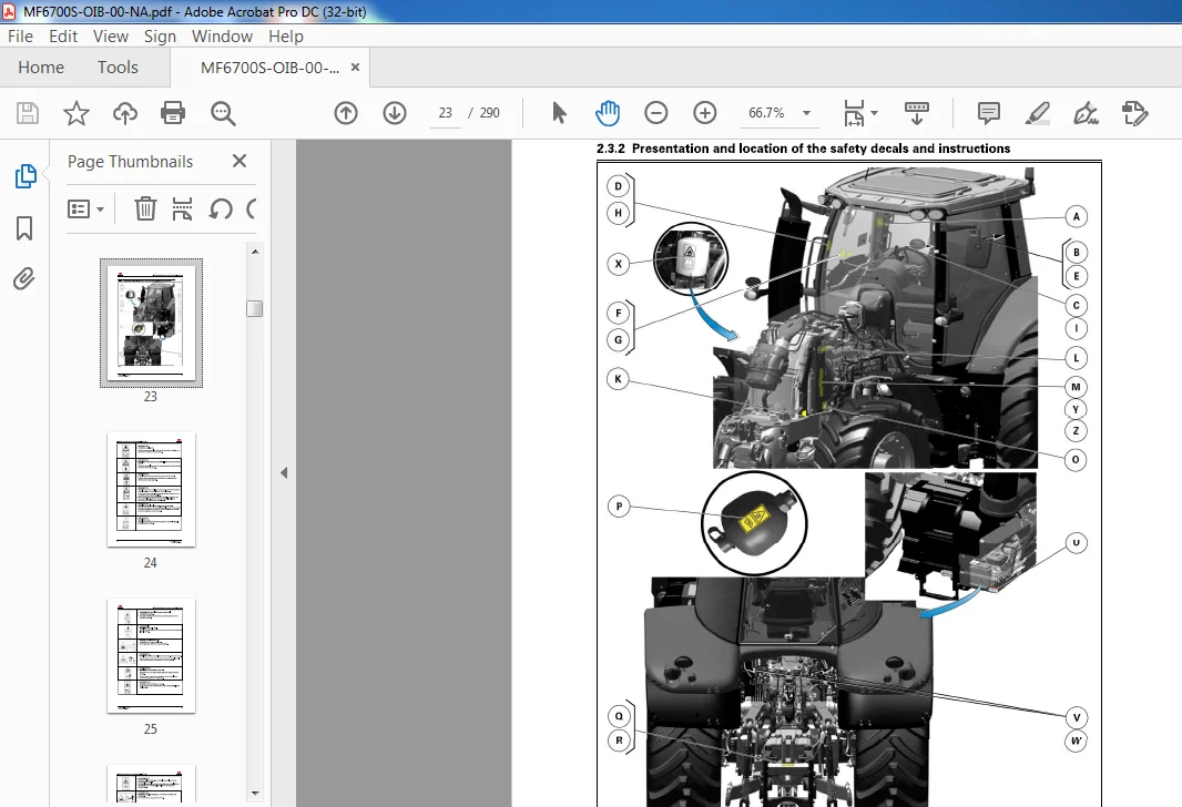
2 3 2 Presentation and location of the safety decals and instructions 2 3
2 4 General safety instructions 28
2 4 1 Awareness of the safety instructions and symbols 2 8
2 4 2 Operator familiarity in the use of the tractor 2 8
2 4 3 Filling the fuel tank 2 9
2 4 4 Mounting and dismounting the operator’s seat 2 9
2 4 5 Mandatory procedure before dismounting the tractor 3 0
2 5 Special safety instructions for preparing the tractor for use 31
2 5 1 Protective clothing 3 1
2 5 2 Activated carbon filter information 3 1
2 5 3 Safety devices and items 3 4
2 5 4 Checking the tractor 3 4
2 6 Specific safety instructions for starting the tractor 36
2 6 1 Protection of persons other than the operator 3 6
2 6 2 Start up safely 3 6
2 6 3 Starting the tractor with jump start cables 3 7
2 6 4 Checks to be carried out after start-up 3 8
2 7 Specific safety instructions for using the tractor 39
2 7 1 General instructions 3 9
2 7 2 Protection of persons other than the operator 4 0
2 7 3 Overturning 4 0
2 7 4 Tractor towing 4 3
2 7 5 Regulatory data on maximum permitted trailed weights 4 3
2 7 6 Road use 4 7
2 7 7 Parking brake 4 9
2 7 8 Power take-off 4 9
2 7 9 Implements 5 0
2 7 10 Front-end loader 5 2
2 8 Specific safety instructions for servicing the tractor 53
2 8 1 Pollution warning to observe when servicing the tractor 5 3
2 8 2 General instructions 5 3
2 8 3 Handling instructions 5 4
2 8 4 Special instructions for cleaning the tractor 5 6
2 9 Protective structures 57
2 9 1 Protective structures – Use and accreditation 5 7
2 9 2 Cab 5 7
2 9 3 Seat belt 5 7
Operation – MF 6700 S
ACT001898A_ed2
Table of contents
2 9 4 Instructor seat 5 8
2 10 Warranty 5 9
2 10 1 General 5 9
2 10 2 Pre-delivery inspection and commissioning on the user’s premises 5 9
2 10 3 Warranty procedure 5 9
2 10 4 Procedure to follow if changing region 5 9
2 10 5 Servicing during and after the warranty period 60
2 10 6 California emission control warranty statement 60
2 10 7 Emission reduction warranty statement for the United States and Canada 63
3 Usage 6 9
3 1 Operator environment 7 3
3 1 1 S teering console 73
3 1 2 Instrument panel 7 4
3 1 3 Control unit 8 0
3 1 4 Pedals 8 1
3 1 5 Steering wheel 8 1
3 1 6 O perator presence detector 8 2
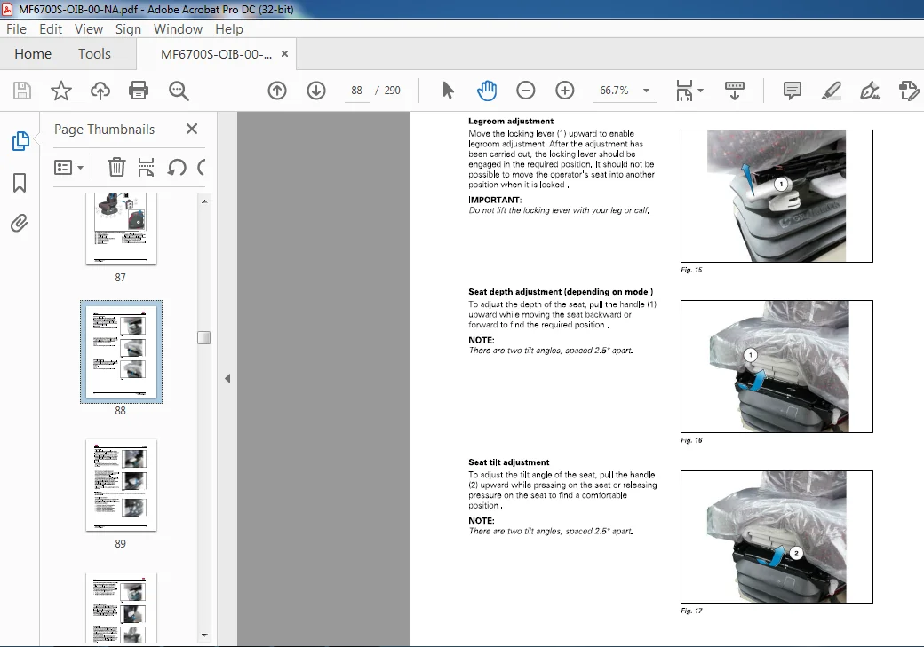
3 1 7 Automatic adjustment pneumatic seat 8 6
3 1 8 Instructor seat 9 2
3 1 9 Right-hand console 9 3
3 1 10 Command Control Armrest 9 3
3 1 11 Right-hand pillar 9 5
3 1 12 Left-hand console 9 6
3 1 13 Upper console 9 7
3 1 14 Manual air conditioning 9 9
3 1 15 Automatic air conditioning 10 4
3 1 16 Additional heater 110
3 1 17 Accessories sockets 111
3 1 18 Emergency exits 113
3 1 19 Sun visor 113
3 1 2 0 Roof hatch 114
3 1 2 1 Wheel chock(s) (optional) 115
3 2 Setup and Information Screen control screens on the instrument
panel 117
3 2 1 Using the Setup and Information Screen 117
3 2 2 Setup and Information screens 119
3 3 Body 127
3 3 1 Opening the bonnet 12 7
3 3 2 Adjusting the external rear-view mirrors 12 7
3 3 2 1 Positioning the arms 12 7
3 3 2 2 Adjusting the arm extensions (depending on model) 12 8
3 3 2 3 Rear-view mirror with manual adjustment 12 8
3 3 2 4 Rear-view mirror with electric adjustment 12 8
3 4 Engine 130
3 4 1 Running-in 13 0
3 4 2 Filling with fuel 13 0
3 4 3 Start switch 13 2
3 4 4 Start-up 13 2
3 4 5 Starting the SCR Technology engine in cold weather 13 3
3 4 6 Information about the various operating modes of the SCR Technology engine 13 5
3 4 7 Stopping the engine 14 0
3 4 8 Engine speed 14 0
3 4 9 Storing engine speeds 14 2
3 5 Transmission 144
3 5 1 Presentation of the different driving modes 14 4
3 5 2 Clutch function 14 4
Operation – MF 6700 S
ACT001898A_ed2
3 6
3 7
3 8
3 9
Table of contents
3 5 3 PowerShuttle 14 5
3 5 3 1 PowerShuttle Protection Function 14 7
3 5 4 Adjusting the start ratios ( 1A , 1B , 1C etc ) 14 7
3 5 5 Storing the transmission ratios ( 1A , 1B , 1C , etc ) 14 8
3 5 6 Lever (Speedmatching) mode 15 0
3 5 7 Pedal (AutoDrive) mode 15 2
3 5 8 Road mode (Hare)/Field mode (Tortoise) 15 4
3 5 9 Changing the transmission ratios ( 1A , 1B , 1C etc ) 1 5 6
3 5 10 Optional super creeper range (snail) 15 6
3 5 11 Tractor towing 15 7
3 5 12 Forward speed calibration 15 8
Brakes 159
3 6 1 Brake pedals 15 9
3 6 2 Hydraulic trailer brake 15 9
3 6 3 Pneumatic trailer brake 160
3 6 4 Parking brake 161
Steering 163
3 7 1 Steering 163
Front axle 166
3 8 1 Four-wheel drive front axle 166
3 8 2 Suspended front axle 167
3 8 3 Permissible load on the front axle 169
Differential lock 172
3 9 1 Differential lock 17 2
3 10 Power take-off 174
3 10 1 Front power take-off 174
3 10 2 Rear power take-off ( PTO) 174
3 10 2 1 Selecting the power take-off speed 175
3 10 2 2 Adjusting the progressivity of power-take-off engagement 17 6
3 10 2 3 Engaging PTO in manual mode: 17 6
3 10 2 4 Engaging PTO in automatic mode: 17 6
3 10 3 Economy PTO 177
3 10 4 GS PTO (optional) 17 8
3 10 5 Changing the flanged shaft 179
3 10 6 PTO external control 180
3 10 7 Power take-off electronic controls 18 1
3 10 8 Power take-off protection 18 1
3 11 Linkage 183
3 11 1 General 18 3
3 11 2 Rear linkage electronic controls 18 4
3 11 3 Rear linkage operation 18 6
3 11 4 Rear linkage external controls 19 1
3 11 5 Front linkage 19 1
3 11 6 Top link 19 7
3 11 7 Bottom links 19 9
3 11 8 Lift rods 2 0 0
3 11 9 Stabilizers 2 0 2
3 11 9 1 Stabilizers with manual telescopic adjustment 2 0 2
3 11 9 2 Automatic stabilizers 2 0 3
3 11 9 3 Stabilizers with shoes 2 0 4
3 11 10 Ball joint support 2 0 5
3 12 Towing equipment 206
3 12 1 General 2 0 6
3 12 2 Swinging drawbar 2 11
3 12 2 1 Fitting the swinging drawbar 2 12
3 13 Auxiliary hydraulics 213
Operation – MF 6700 S
ACT001898A_ed2
Table of contents
3 13 1 General 2 13
3 13 2 Description of hydraulic couplers on Closed Center system ( Load Sensing) 2 13
3 13 3 Use of hydraulic couplers on Closed Center system (Load Sensing) 2 15
3 13 4 Auxiliary hydraulics locking/unlocking 2 2 0
3 13 5 Hydraulics control lever 2 2 1
3 13 6 Description and use of the cab controls 2 2 2
3 13 7 Description and use of the external controls 2 2 9
3 13 8 Setting flow rates and time delay 2 2 9
3 13 9 Emergency manual spool valve control 2 3 1
3 14 Standard front-end loader function 232
3 14 1 Front-end loader 2 3 2
3 14 2 Layout of components 2 3 2
3 14 3 Standard front-end loader connection 2 3 3
3 14 4 Using the electric joystick of the standard front-end loader 2 3 4
3 14 4 1 Joystick functions for the standard front-end loader 2 3 4
3 14 4 2 Floating position with the standard front-end loader 2 3 4
3 14 4 3 Displaying the flow rates of the standard front-end loader 2 3 5
3 14 4 4 Arm suspension on the standard front-end loader 2 3 7
3 14 4 5 Locking and unlocking standard front-end loader accessories 2 3 7
3 14 4 6 Standard front-end loader/engine speed automation 2 3 8
3 14 4 7 3rd and 4th functions of the standard front-end loader 2 3 8
3 14 4 8 Automatic shaking function of the standard front-end loader implement 2 3 9
3 15 Front-end loader function with 3rd function option 240
3 15 1 Front-end loader 2 4 0
3 15 2 Layout of components 2 4 0
3 15 3 Front-end loader connection with 3rd function option 2 4 1
3 15 4 Using the front-end loader electric joystick with the 3rd function option 2 4 2
3 15 4 1 Joystick functions for the front-end loader with the 3rd function option 2 4 2
3 15 4 2 Floating position of the front-end loader with the 3rd function option 2 4 2
3 15 4 3 Displaying the front-end loader flow rates with the 3rd function option 2 4 3
3 15 4 4 Arm suspension on the front-end loader with the 3rd function option 2 4 5
3 15 4 5 Locking and unlocking front-end loader accessories with the 3rd function
option 2 4 5
3 15 4 6 Front-end loader/engine speed automation with the 3rd function option 2 4 6
3 15 4 7 Automatic shaking function for the front-end loader implement with the
3rd function option 2 4 6
3 15 5 Unhitching the front-end loader with the 3rd function option 2 4 6
3 16 Lighting 248
3 16 1 Main lighting control module 2 4 8
3 16 2 Work lights module 2 4 9
3 16 3 Direction indicators 2 5 0
3 17 Suspended cab 254
3 17 1 Suspended cab 2 5 4
3 18 Front tires and track widths 257
3 18 1 Wheel studs 2 5 7
3 18 2 Installation points of the axle stands 2 5 7
3 18 3 Adjusting the front wheel track width 2 5 8
3 18 4 Adjusting the 4WD front axle stops 2 6 1
3 18 4 1 Fitting the oscillation stops 2 6 1
3 18 4 2 Adjusting the steering angle 2 6 1
3 18 4 3 Toe-in check 2 6 2
3 18 4 4 Adjusting the front fenders Shoe side adjustment on the front axle 2 6 2
3 18 4 5 Adjusting the front fenders Adjusting the height of the support on the
shoe 2 6 2
3 18 4 6 Adjusting the front fenders Adjusting the lateral position of the fender
on the support (two adjustments are possible) 2 6 3
3 18 5 Tires 2 6 3
Operation – MF 6700 S
ACT001898A_ed2
Table of contents
3 18 6 Tire pressures 2 6 3
3 19 Rear tires and track widths 264
3 19 1 Wheel studs 2 64
3 19 2 Installation points of the axle stands 2 64
3 19 3 Rear track width with flanged shafts 2 65
3 19 4 Rear track width with short straight shafts 2 67
3 19 5 Rear track width with long straight shafts 2 7 1
3 19 6 Adjusting the rear wheel track width 2 7 3
3 19 6 1 Adjustment of wheel position on the straight shaft 2 7 4
3 19 6 2 Adjustment of wheel position on the straight shaft 2 7 4
3 20 Dual wheels 276
3 2 0 1 Dual wheels 2 7 6
3 2 0 2 Installation points of the axle stands 2 77
3 2 0 3 Dual rear wheel track width with long straight shafts 2 7 8
3 21 Ballast 284
3 2 1 1 Liquid ballasting 2 8 4
3 2 1 2 Front-end weight 2 8 4
Operation –
MASSEY FERGUSON MF 6700S SERIES 6713S 6714S 6715S 6716S 6718S DYNA-6 OPERATOR INSTRUCTION MANUAL – PDF DOWNLOAD:
IMAGES PREVIEW OF THE MANUAL:
PLEASE NOTE:
- This is not a physical manual but a digital manual – meaning no physical copy will be couriered to you. The manual can be yours in the next 2 mins as once you make the payment, you will be directed to the download page IMMEDIATELY.
- This is the same manual used by the dealers inorder to diagnose your vehicle of its faults.
- Require some other service manual or have any queries: please WRITE to us at [email protected]
S.V