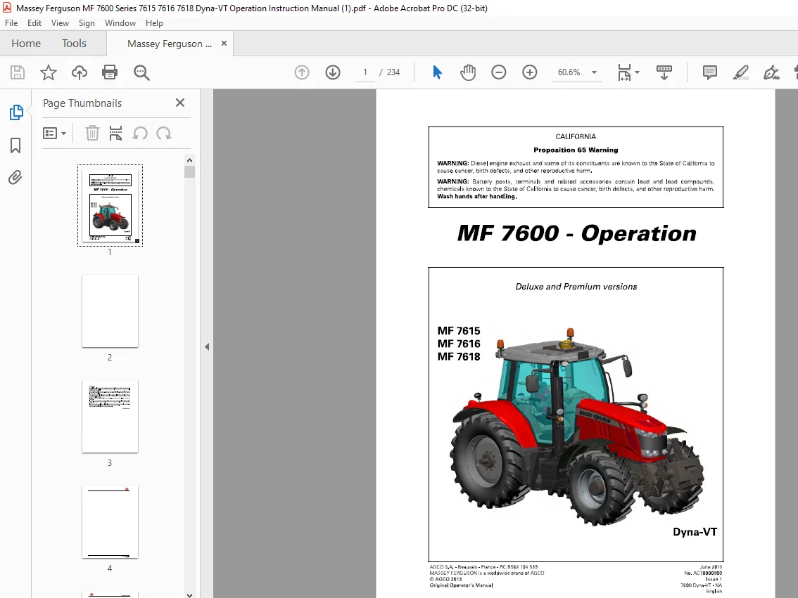
Massey Ferguson MF 7600 Series 7615 7616 7618 Dyna VT Operation Instruction Manual – PDF DOWNLOAD
Original price was: $62.95.$28.95Current price is: $28.95.
Massey Ferguson MF 7600 Series 7615 7616 7618 Dyna VT Operation Instruction Manual – PDF DOWNLOAD
Description
Massey Ferguson MF 7600 Series 7615 7616 7618 Dyna VT Operation Instruction Manual – PDF DOWNLOAD
DESCRIPTION:
Massey Ferguson MF 7600 Series 7615 7616 7618 Dyna VT Operation Instruction Manual – PDF DOWNLOAD
Foreword :
We would like to welcome you to the ever-growing number of people who own a Massey Ferguson tractor; people who appreciate quality. We are proud of every tractor that leaves our factories, each being technically advanced and of high quality. This Operator’s Manual contains the specifications for your new tractor. Please ensure that all operators read the instructions and follow them carefully. The pages that follow contain vital information on your tractor; please read them carefully.
- Your Massey Ferguson dealer will guarantee you quality servicing and will provide you with all the assistance you need. When it comes to servicing, remember that your dealer knows your tractor best and that he wants you to be completely satisfied. Please leave this Operator’s Manual in the tractor if resold.
- The subsequent owner will need the information it contains. All information and specifications in this manual are up to date at the time of publication. However, our ongoing policy to improve our products obliges us to reserve the right to make alterations at any time without notice.
- Please note that this manual relates to all models and refers to both standard and optional equipment. You may therefore find details relating to equipment that is not fitted on your tractor. This Operator’s Manual complies with Directive 2010/52 EC.
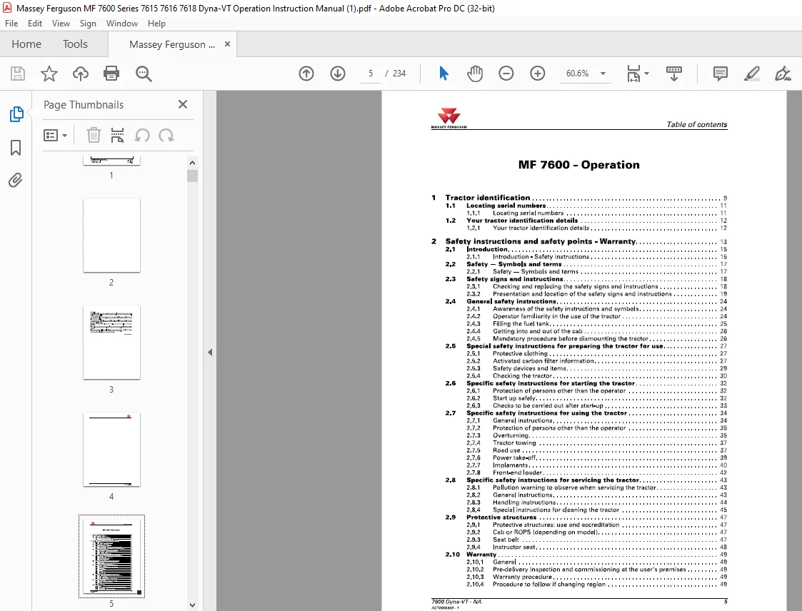
TABLE OF CONTENTS:
Massey Ferguson MF 7600 Series 7615 7616 7618 Dyna VT Operation Instruction Manual – PDF DOWNLOAD
1 Tractor identification 9
1 1 Locating serial numbers 11
1 1 1 Locating serial numbers 11
1 2 Your tractor identification details 12
1 2 1 Your tractor identification details 12
2 Safety instructions and safety points – Warranty 13
2 1 Introduction 15
2 1 1 Introduction – Safety instructions 15
2 2 Safety – Symbols and terms 17
2 2 1 Safety – Symbols and terms 17
2 3 Safety signs and instructions 18
2 3 1 Checking and replacing the safety signs and instructions 18
2 3 2 Presentation and location of the safety signs and instructions 19
2 4 General safety instructions 24
2 4 1 Awareness of the safety instructions and symbols 24
2 4 2 Operator familiarity in the use of the tractor 24
2 4 3 Filling the fuel tank 25
2 4 4 Getting into and out of the cab 26
2 4 5 Mandatory procedure before dismounting the tractor 26
2 5 Special safety instructions for preparing the tractor for use 27
2 5 1 Protective clothing 27
2 5 2 Activated carbon filter information 27
2 5 3 Safety devices and items 29
2 5 4 Checking the tractor 30
2 6 Specific safety instructions for starting the tractor 32
2 6 1 Protection of persons other than the operator 32
2 6 2 Start up safely 32
2 6 3 Checks to be carried out after start-up 33
2 7 Specific safety instructions for using the tractor 34
2 7 1 General instructions 34
2 7 2 Protection of persons other than the operator 35
2 7 3 Overturning 35
2 7 4 Tractor towing 37
2 7 5 Road use 37
2 7 6 Power take-off 39
2 7 7 Implements 40
2 7 8 Front-end loader 42
2 8 Specific safety instructions for servicing the tractor 43
2 8 1 Pollution warning to observe when servicing the tractor 43
2 8 2 General instructions 43
2 8 3 Handling instructions 44
2 8 4 Special instructions for cleaning the tractor 45
2 9 Protective structures 47
2 9 1 Protective structures: use and accreditation 47
2 9 2 Cab or ROPS (depending on model) 47
2 9 3 Seat belt 47
2 9 4 Instructor seat 48
2 10 Warranty 49
2 10 1 General 49
2 10 2 Pre-delivery inspection and commissioning at the user’s premises 49
2 10 3 Warranty procedure 49
2 10 4 Procedure to follow if changing region 49
7600 Dyna-VT- NA
ACT0000900 – 1
5
Table of contents MASSEY FERGUSON
2 10 5
2 10 6
2 10 7
Servicing during and after the warranty period 50
California emission control warranty statement 50
California emission reduction control warranty for the United States and
Canada 52
3 Operation 57
6
3 1 Cab 61
3 1 1 Steering console 61
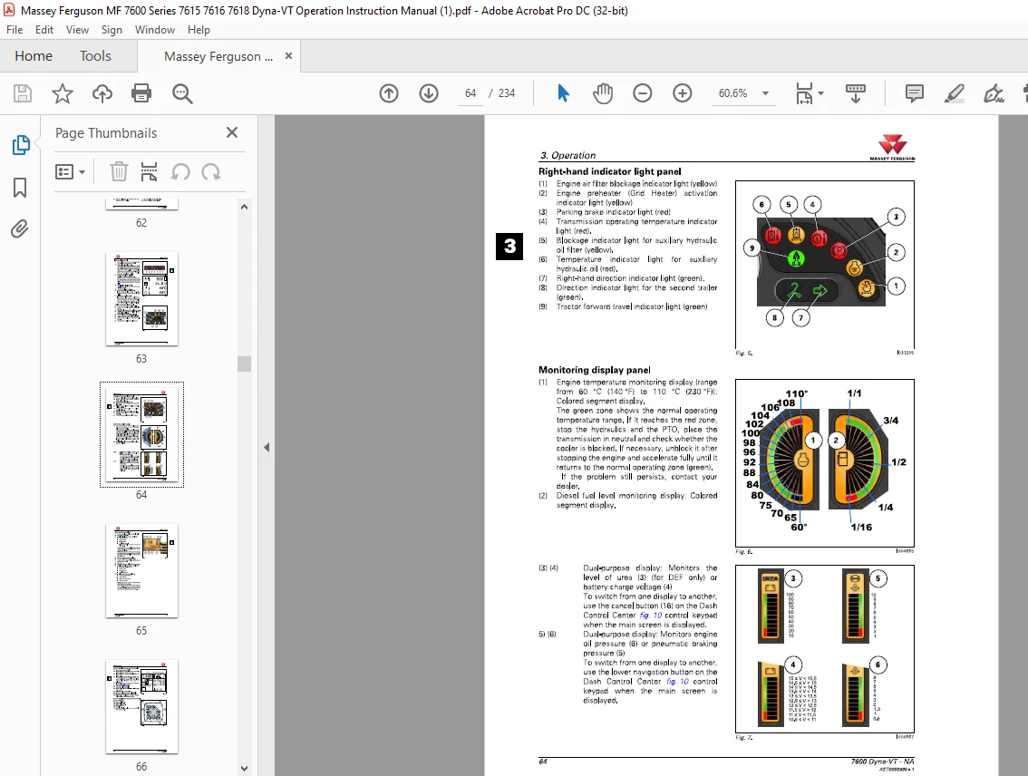
3 1 2 Instrument panel 62
3 1 3 Control unit 67
3 1 4 Pedals 67
3 1 5 Steering Wheel 68
3 1 6 Operator presence detector 68
3 1 7 Automatic adjustment pneumatic seat 70
3 1 8 Right-hand console 77
3 1 9 Armrest Command Control Armrest 78
3 1 10 Right-handpillar 80
3 1 11 Left-hand console 81
3 1 12 Upper console 81
3 1 13 Air conditioning 83
3 1 14 Additional heater 88
3 1 15 Accessories sockets 88
3 1 16 Emergency exits 89
3 1 17 Cab safety 90
3 1 18 Sun visor 90
3 1 19 Roofhatch 91
3 1 20 Wheel chock(s) (optional) 92
3 2 Dash Control Center control screens on the instrument panel 94
3 2 1 Using the Dash Control Center screen 94
3 2 2 Dash Control Center screens 94
3 3 Body 99
3 3 1 Opening the hood 99
3 3 2 Adjusting the external rear-view mirrors 100
3 4 Engine 102
3 4 1 Running-in 102
3 4 2 Filling with fuel 102
3 4 3 Start switch 104
3 4 4 Start-up 104
3 4 5 Start-up sheet 106
3 4 6 Cold weather starting 107
3 4 7 Information about the various operating modes of the e3 SCR Technology
engine 107
3 4 8 Stopping the engine 110
3 4 9 Engine speed 111
3 5 Transmission 112
3 5 1 Presentation of the different driving modes 112
3 5 2 Clutch function 112
3 5 3 PowerShuttle 113
3 5 4 Setting start-up speeds 115
3 5 5 Storage of forward speeds 116
3 5 6 Engine underspeed supervisor 118
3 5 7 Lever mode 119
3 5 8 Pedal mode 122
3 5 9 Self-propelled mode 124
3 5 10 Dyna-Step mode 125
3 5 11 road mode (hare)/field mode (tortoise) 126
3 5 12 Changing forward speed 128
3 5 13 Tractor towing 128
3 5 14 Forward speed calibration 132
3 6 Brakes 134
3 6 1 Brake pedals 134
3 6 2 Hydraulic trailer brake 134
7600 Dyna-VT – NA
ACT0000900 • 1
MASSEY FERGUSON Table of contents
3 6 3 Pneumatic trailer brake 135
3 6 4 Parking brake 136
3 7 Steering 137
3 7 1 Steering 137
3 8 Front axle 140
3 8 1 Four-wheel drive front axle 140
3 8 2 Suspended front axle 141
3 9 Differential lock 143
3 9 1 Differential lock 143
3 10 Power take-off 145
3 10 1 Front power take-off 145
3 10 2 Rear power take-off (PTO) 146
3 10 3 Economy PTO 148
3 10 4 Changing the flanged shaft 149
3 10 5 PTO external control 151
3 10 6 Power take-off electronic controls 151
3 10 7 Powertake-offprotection 152
3 11 Linkage 153
3 11 1 General 153
3 11 2 Rear linkage electronic controls 153
3 11 3 Rear linkage operation 154
3 11 4 Rear linkage external controls 160
3 11 5 Front linkage 161
3 11 6 Top link 164
3 11 7 Bottom links 166
3 11 8 Lift rods 168
3 11 9 Stabilizers 169
3 11 10 Ball joint support 172
3 12 Towing equipment 173
3 12 1 General 173
3 12 2 Swinging drawbar 174
3 12 3 Three-point linkage Quick linkage hitch 177
3 13 Auxiliary hydraulics 179
3 13 1 General 179
3 13 2 Description of hydraulic couplers on Closed Center system (Load Sensing) 179
3 13 3 Use of hydraulic couplers on Closed Center system (Load Sensing) 182
3 13 4 Locking/unlocking the controls 187
3 13 5 Description and use of the cab controls 188
3 13 6 Hydraulics control lever 192
3 13 7 Setting flow rates and time delay 194
3 13 8 Emergency manual spool valve control 195
3 14 Front-end loader function 196
3 14 1 Front-end loader 196
3 14 2 Layout of components 196
3 14 3 Using the front-end loader controls 197
3 15 Lighting 201
3 15 1 Main lighting control module 201
3 15 2 Right-hand pillar, work lights module 202
3 16 Suspended cab 203
3 16 1 Suspended cab 203
3 17 Front tires and track widths 205
3 17 1 Wheel studs 205
3 17 2 Installation points of the axle stands 205
3 17 3 Adjusting the front wheel track width 206
3 17 4 Adjusting the 4WD front axle stops 208
3 17 5 Tires 211
3 17 6 Tire pressures 211
3 18 Rear tires and track widths 212
3 18 1 Wheel studs 212
3 18 2 Installation points ofthe axle stands 212
3 18 3 Rear track width with flanged shafts 213
3 18 4 Rear track width with short straight shafts 214
7600 Dyna-VT- NA
ACT0000900 – 1
7
Table of contents MASSEY FERGUSON
3 18 5 Rear track width with long straight shafts 217
3 18 6 Adjusting the rear wheel track width 219
3 19 Dual wheels 221
3 19 1 Dual wheels 221
3 19 2 Installation points of the axle stands 222
3 19 3 Dual rear wheel track width with short straight shafts 223
3 19 4 Dual rear wheel track width with long straight shafts 227
3 19 5 Adjusting the rear wheel track width 232
3 20 Ballast 234
3 20 1 Liquid ballasting 234
MASSEY FERGUSON MF 7600 SERIES 7615 7616 7618 DYNA VT OPERATION INSTRUCTION MANUAL – PDF DOWNLOAD:
IMAGES PREVIEW OF THE MANUAL:
PLEASE NOTE:
- This is the SAME manual used by the dealers to troubleshoot any faults in your vehicle. This can be yours in 2 minutes after the payment is made.
- Contact us at [email protected] should you have any queries before your purchase or that you need any other service / repair / parts operators manual.
S.V