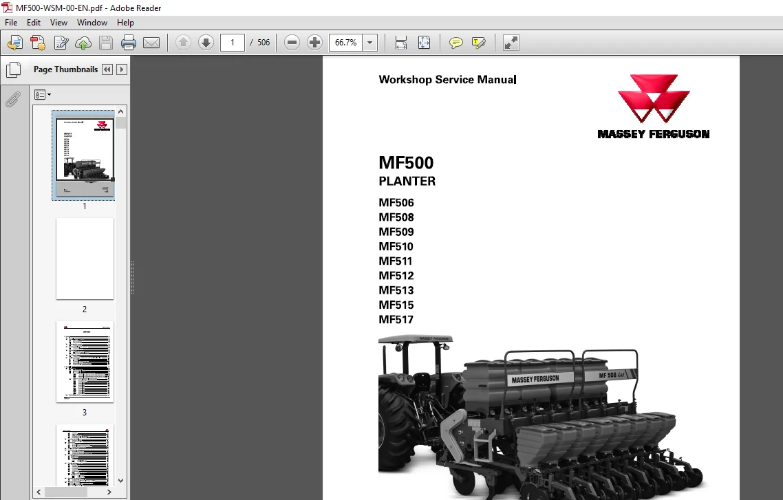
Massey Ferguson MF500 Planter 506 508 509 510 511 512 513 515 517 Service Manual – PDF DOWNLOAD
Original price was: $86.95.$29.95Current price is: $29.95.
Massey Ferguson MF500 Planter 506 508 509 510 511 512 513 515 517 Service Manual – PDF DOWNLOAD
Description
Massey Ferguson MF500 Planter 506 508 509 510 511 512 513 515 517 Service Manual – PDF DOWNLOAD
DESCRIPTION:
Massey Ferguson MF500 Planter 506 508 509 510 511 512 513 515 517 Service Manual – PDF DOWNLOAD
FOREWORD:
The purpose of this manual is to enable the owner and ope ratorto operate the implement safely and appropriately. If the instructions are followed correctlyr the implement will work for many years, following the MASSEY FERGUSON tradition. Configuring and adjusting the implement in the dealership will ensure that these operating and service instructions are properly understood. Always consult the dealer if any part of the manual is not understood.
- It is extremely important that these instructions are understood and followed. Daily maintenance should become a routine. Always keep a record of the service hours. When ordering new parts, use only original MASSEY FERGUSON parts. The MASSEY FERGUSON dealer network provides original parts and can give instructions for installation and use. Using low quality parts can seriously damage the equipment. We recommend that customers buy service parts from authorised MASSEY FERGUSON dealers only. Due to variations in operating conditions, it is impossible for the manufacturer to make comprehensive or definitive statements in its publications with respect to the performance or usage methods of its machines, or to be responsible for any damages or losses arising from such statements, errors or omissions.
- To prevent the warranty being invalidated, consult your MASSEY FERGUSON dealer for special instructions if the tractor will be used in special conditions that may be harmful (use in deep waters or in flooded fields, for example). These products were designed for agricultural applications only (appropriate use). Any other use shall be considered inappropriate.
- MASSEY FERGUSON is not liable for damage to property or personal injuries caused by improper use. The user must take full responsibility for the consequences of misuse. Conformity and full adherence to the operation, service and maintenance requirements specified by MASSEY FERGUSON are essential factors for appropriate use. These implements must be operated and maintained only by qualified personnel familiar with their features, in addition to the safety rules and standards (accident prevention). It is recommended that customers contact one of the MASSEY FERGUSON dealerships in the event of post-sale problems and for any adjustment that may be required.
Genera l Recom mendations
Why is safety important ?
1. Accidents incapacitate and сап Ье fatal
2 . Accidents generally involve significant costs
3. Accidents сап Ье avoided.
This section of the Manual is intended to point out some of the basic safety situations involved with your equipment and to provide suggestions on how to avoid high-risk situations and accidents. Therefore, users must take all possible precautions and guidance. There are always a series of precautions to be taken for each implement, attachment and work situation, which would be impossible to list in this Manual. MASSEY FERGUSON is in no way able to directly control the conditions of use, servicing or repair to which the product is subjected. Therefore, users are responsible for always following appropriate practices for their safety and for the integrity of the product, other people or machines in the same work area.
TABLE OF CONTENTS:
Massey Ferguson MF500 Planter 506 508 509 510 511 512 513 515 517 Service Manual – PDF DOWNLOAD
1 Security 1-1
1 1 lntroduction 1-3
1 2 General Recommendations 1-4
1 2 1 Safety notes 1-4
1 2 2 Note to the operator 1-4
1 2 3 Safe maintenance 1-5
1 3 Follow а safety program 1-6
1 3 1 For ргорег operation 1-6
1 4 Prepare yourself for safe operation 1-7
1 4 1 Protect yourself 1-7
1 4 2 Protect the environment 1-7
1 5 Safe Operation 1-8
1 5 1 General operating hazards 1-8
1 5 2 lmplements and additional equipment 1-8
1 5 3 Safety practices 1-9
1 6 Road Transport 1-11
1 6 1 Transport оп truck 1-1 1
1 7 Quality, environment, safety and occupational health policy 1-12
1 7 1 Main guidelines 1-1 2
1 7 2 ISO 1 4000 1-1 2
1 7 3 Environmental Management System 1-1 2
1 7 4 Environmental issues 1-1 2
1 7 5 Recommendations for users and customers 1-1 3
1 7 6 CONAMA Resolution 1-1 4
2 General lnfo 2-1
2 1 lntroduction 2-3
2 1 1 lmplement ldentification 2-3
2 1 2 Contacting Technical Support 2-4
2 1 3 lndicative decals 2-4
2 1 4 Generic tаЫе of torques recommended for screws 2-8
2 1 4 1 Generic tаЫе of tightening torques for nuts and screws, in Nm 2-9
2 1 4 2 Generic tаЫе of tightening torques for nuts and screws, in Nm 2-9
2 1 4 3 Generic tаЫе of tightening torques for nuts and screws, in Nm 2-10
2 1 4 4 Generic tаЫе of tightening torques for nuts and screws, in Nm 2-10
2 1 5 Conversion between units – lmperial and metric systems 2-1 1
2 1 5 1 Technical unit prefixes 2-1 1
2 1 5 2 Name of the prefixes 2-1 1
2 1 5 3 Technical units 2-1 2
2 1 5 4 Technical units 2-1 3
2 1 5 5 Technical units 2-1 3
2 1 5 6 Technical units 2-1 3
2 1 5 7 Technical units 2-1 3
2 1 5 8 Technical units 2-1 4
2 1 5 9 Technical units 2-1 4
2 1 5 10 Technical units 2-1 5
2 1 5 1 1 Technical units 2-1 5
2 1 5 1 2 Technical units 2-1 5
2 1 5 1 3 Technical units 2-1 6
2 2 Technical Specifications 2-1 7
2 2 1 Presentation 2-17
2 2 2 Dimensions 2-2 7
2 2 3 Fertiliser distribution tаЫе 2-3 3
2 2 4 Seed distribution tаЫе – Mechanical 2-3 6
2 2 5 Seed distribution tаЫе – Precision planting 2-3 8
2 3 Preparing the implement 2-41
2 3 1 Hitching the implement 2-4 1
2 3 2 Disengage the implement 2-4 3
2 4 Transmission 2-45
2 4 1 Spreading Fertilizer 2-4 5
2 4 2 Mechanical Pivoted Seed Transmission (L) 2-4 6
2 4 3 Mechanical Pantograph Seed Transmission (М) 2-4 7
2 4 4 Pneumatic Seed Transmission (Н} 2-4 8
2 5 Fertiliser distribution 2-49
2 6 Seed distribution 2-51
2 6 1 Mechanical seed distribution 2-5 1
2 6 2 Pneumatic seed distribution 2-5 2
2 6 3 Pneumatic seed distribution – Precision Planting 2-5 6
2 7 Preparation 2-58
2 7 1 lnitial Settings 2-5 8
2 7 2 ltems to check 2-5 8
2 7 3 Travel 2-59
2 7 4 Adjustments 2-59
2 7 4 1 Practical fertilizer test 2-59
2 7 4 2 Practical seed test 2-59
2 8 Periodic maintenance points 2-61
2 8 1 lntroduction 2-6 1
2 8 2 Lubrication points 2-6 1
2 8 3 Retightening 2-6 5
2 8 4 Lubricant 2-6 9
2 8 5 Tire pressure 2-6 9
2 8 6 Stretching the chains 2-6 9
2 8 7 Ratchets system 2-70
2 8 7 1 Adjusting the ratchets 2-70
Fertilizer reservoir 2-71
ldentification of meter threads 2-72
2 8 9 1 Left-hand auger 2-72
2 8 9 2 Right-hand auger 2-73
2 9 Changing the seed disks 2-75
2 9 1 Changing discs – Mechanical line 2-75
2 9 2 Changing the discs – Precision Planting pneumatic line 2-77
2 10 Changing the spacing 2-80
2 10 1 Procedure for moving and repositioning the wheel 2-8 1
2 10 2 lnstalling the wheel hub 2-8 7
2 10 3 AssemЫing the wheel shaft 2-8 8
2 10 4 Procedure for repositioning the lines 2-8 8
2 10 5 Repositioning the ratchet system 2-90
2 10 6 Representation of spacing between the lines 2-9 1
2 11 Shims 2-121
2 12 Accessories 2-122
2 12 1 Line marker 2-1 2 2
2 12 1 1 Line marker pre-assemЫy 2-1 2 2
2 12 1 2 lnstalling the row marker 2-12 3
2 12 1 3 lnstalling the line marker disc 2-1 2 4
2 12 1 4 Fitting the row marker frame 2-1 2 5
2 12 1 5 Adjusting the line marker 2-12 6
2 12 1 6 Adjusting the length of the mагkег агm 2-12 7
2 12 1 7 Adjusting the marker агm disc’s angle of actuation 2-12 7
2 12 1 8 Adjusting the disc’s vertical angle of actuation 2-12 8
V R D system 2-12 9
2 1 2 2 1 code 2-1 3 0
2 1 2 2 2 С3 000 installation 2-1 3 4
lnstalling and configuring the V R D system саЬ kit 2-1 3 9
2 12 3 1 Without саЬ kit 2-1 3 9
2 12 3 2 With GX-4 5 autopilot 2-1 3 9
2 12 3 3 With Auto-Guide 3 000 autopilot 2-1 4 0
2 12 3 4 Without on-board technology 2-1 4 0
Planting monitor 2-1 4 0
2 1 2 4 1 Presentation 2-1 4 0
2 1 2 4 2 Technical Specifications 2-1 4 1
2 1 2 4 3 Overview of the monitor 2-1 4 2
2 1 2 4 4 lnstallation 2-1 4 5
3 Row unit 3-1
3 1 Cutting disk 3-3
3 1 1 Preparation and саге during maintenance 3-3
3 1 2 General lnformation 3-3
3 1 3 Cutting disc 3-3
3 1 3 1 Adjusting the cutting disc pressure 3-4
3 1 4 Disc assemЫy components and options 3-4
3 1 4 1 Adjusting the cutting disc pressure 3-5
3 1 5 Soil Breaker System ( Seed Version) 3-5
3 1 6 Removing and installing the cutting disk row 3-6
3 1 7 DisassemЫing the cutting disk assemЬly 3-6
3 2 Fertilizer line 3-9
3 2 1 Preparation and саге during maintenance 3-9
3 2 2 Fertilizer Line 3-9
3 2 2 1 Adjusting the pressure in the line 3-10
Adjusting the pressure in the line 3-10
Furrowers 3- 11
Furrower 3-11
D isarm/ Агm Furrower 3-1 2
3 2 6 1 Adjusting the disarm/arm furrower pressure 3-1 3
3 2 7 Fertilizer DouЫe Disc 3-1 4
3 2 8 Removing the fertilizer line 3-1 4
3 2 9 AssemЫing the fertilizer line 3-1 5
Seed line 3-17
3 3 1 Preparation and саге during maintenance 3-17
3 3 2 General lnformation 3-17
3 3 3 Mechanical Seed Line 3-17
3 3 3 1 AssemЫing the coupler base 3-1 8
3 3 3 2 AssemЫing the mechanical seed meter 3-2 1
3 3 3 3 lnstalling the transmission chain 3-2 2
Pneumatic Seed Line 3-2 3
3 3 4 1 Precision Planting seed meters 3-2 4
Seed line 3-3 5
Pivoted Line 3-3 7
3 3 6 1 lnstalling the pivoted seed row 3- 3 7
3 3 6 2 lnstalling the pivoted seed row 3-4 2
3 3 6 3 lnstalling the pivoted transmission journal bearing 3-4 4
Pantograph line 3-4 4
3 3 7 1 lnstalling the pantograph row 3-4 4
3 3 7 2 lnstalling the pantograph row 3-4 7
3 3 7 3 lnstalling the seed гоw journal bearing 3-4 9
3 3 7 4 lnstalling the chain tensioner 3-4 9
3 3 7 5 lnstalling the pantograph гоw 3-50
3 3 7 6 lnstalling the tгansmission саЫе 3-5 4
3 3 7 7 AssemЫing the transmission with the uррег саЫе 3-5 5
Overhead геsегvоiг 3-5 7
3 3 8 1 lnstalling the overhead геsегvоiг 3-5 7
3 3 8 2 lnstalling the overhead reservoir nozzle 3-59
3 3 8 3 lnstalling the overhead геsегvоiг lower nozzle 3-6 0
3 3 8 4 lnstalling the overhead геsегvоiг nozzle valve 3-6 0
3 3 8 5 lnstalling the overhead reservoir оп the chassis 3-6 1
3 3 8 6 Overhead геsегvоiг position 3-6 2
Adjusting the cleaning plates оп the side depth wheel seed discs 3-6 6
AssemЫing the coupler base 3-6 7
lnstalling the meter base 3-6 9
AssemЫing the mechanical seed meter 3-71
lnstalling the seed conductor 3-72
Precision Planting seed meters 3-74
3 3 14 1 Feedgate regulator 3-74
3 3 1 4 2 lnstalling the seed conductor 3-75
3 3 14 3 lnstalling the Precision Planting meter 3-77
3 3 14 4 lnstalling the Precision Planting meter 3-78
3 3 1 4 5 Changing the seed disks – v Drive 3-8 5
Compactor wheels, path clean and ridge fill 3-88
3 4 1 Preparation and саге during maintenance 3-8 8
3 4 2 General lnformation 3-8 8
3 4 3 Depth limiter wheel options 3-8 8
3 4 4 Soil compaction and limitation 3-8 9w
3 4 4 1 Rear Limiter 3-90
3 4 4 2 Lateral disc limiter 3-9 2
3 4 4 3 Compactors 3-9 5
ldentifying the assemЫies 3-9 7
3 4 5 1 Adjusting the “V” and flat compacting wheel settings 3-99
Path Clean Ridge Fill 3-99
3 4 6 1 Adjustment 3-100
3 4 6 2 Adjusting the ridge fill and path clean 3-100
Removing the compacting wheel 3-101
DisassemЫing the compacting wheel 3-101
Removing and installing the side limiter wheels 3-102
DisassemЫing the limiter wheels 3-103
Removing the compacting wheel 3-103
DisassemЫing the compacting wheel 3-104
4 Transmission system 4-1
4 1 Transmission 4-3
4 1 1 Spreading Fertilizer 4-3
4 1 2 Mechanical Pivoted Seed Transmission (L) 4-4
4 1 2 1 lnstalling the pivoted transmission journal bearing 4-5
4 1 3 Mechanical Pantograph Seed Transmission (М) 4-6
4 1 4 Pneumatic Seed Transmission (Н) 4-6
4 2 VRD system transmission – fertilizer 4-8
4 2 1 Right-hand V R D tгansmission – Fertilizer 4- 8
4 2 2 Left-hand V R D transmission – fertilizer 4-11
4 3 VRD system transmission – seeds 4-15
4 3 1 Right-hand V R D tгansmission – seed 4-1 5
4 3 2 Left-hand V R D transmission – Seed 4-2 1
МFБОО
ACW3452200
ТаЬ!е of contents
5 Air System 5-1
5 1 Air system turblne 5-3
5 1 1 Pre-assemЫing the turbine – Precision Planting 5-3
5 1 2 lnstalling the air turbine 5-6
5 1 3 lnstalling the air distribution hoses – Precision Planting 5-7
6 Hydraulic 6-1
6 1 Lift system 6-3
6 2 VariaЫe rate system – VRD 6-4
6 2 1 Operating the VRD system 6-4
6 2 2 Hydraulic schematics 6-4
6 2 3 Pre-installing the valve Ыосk 6-5
6 2 4 lnstalling the valve Ыосk 6-6
6 2 5 Pre-installing the radiator assemЫy 6-7
6 2 6 lnstalling the radiator assemЫy 6-7
6 2 7 VRD hydraulic system – individual machine 6-8
6 2 8 Hydraulic system -Right-hand machine 6-13
6 2 9 VRD hydraulic system – Left-hand machine 6-15
6 3 Removal of air from the system 6-21
6 4 Shims 6-22
7 Electrical 7-1
7 1 Electrical diagrams 7-3
71 1 Electrical diagram 7-5
7 2 VRD assemЬly components 7-7
72 1 VRD electrical system – individual machine 7-7
72 2 VRD electrical system – Tandem machine 7-12
7 3 С3000 Terminal Setup 7-19
73 1 С3000 Software Setup 7-19
73 2 User settings 7-19
73 3 System settings 7-2 3
73 4 Vehicle settings 7-2 7
73 5 lmplement setup 7-2 8
73 6 Fixed rate setup (virtual terminal configuration) 7-3 3
73 6 1 Work home screen 7-3 3
73 6 2 Work screen setup 7-3 4
73 6 3 lnformation items 7-3 5
73 6 4 Recognizing and setting up the modules 7-3 9
73 6 5 lnserting and configuring the product 7-4 4
73 6 6 Calibrating the valves 7-50
73 6 7 Calibrating the fertiliser channel 7-5 2
73 6 8 Calibrating the ground speed 7-5 7
73 6 9 Filling up the seed discs 7-5 9
73 6 10 Diagnostics 7-5 9
73 6 11 Summary (lnformation) 7-60
73 6 12 АСС System 7-6 2
73 6 13 Alarm Log 7-6 3
73 6 14 lmport/Export configuration data 7-6 4
73 7 VагiаЫе Rate Setup 7-6 6
73 71 Work procedure 7-6 6
73 72 Overview of the Work Screen 7-7 4
7 4 РМ 400 Planting Monitor 7-91
МFБОО
74 1 Planter setup function 7-91
74 1 1 Planter Setup 7-91
74 2 Speed setup function 7-92
7 4 2 1 Ground speed setup 7-9 2
Accessories function 7-9 3
7 4 3 1 Fan and shaft setup 7-9 3
7 4 3 2 Flow setup 7-9 4
Population setup function 7-9 4
7 4 4 1 Seed population setup 7-9 5
Auxiliary mode functions 7-9 5
7 4 5 1 Auxiliary modes setup 7-9 5
Display setup -top half 7-9 7
7 4 6 1 Number o f functions setup 7-9 8
Lower display function 7-99
7 4 7 1 lndicator type setup 7-99
General screen functions 7-100
Password function 7-101
Functions monitoring function 7-102
Average plant population 7-103
Maximum/average/minimum population 7-103
Checking the line population 7-103
Spacing between seeds 7-103
Maximum/average/minimum spacing 7-103
Checking the spacing between seeds 7-103
Seed variation Ьу distance 7-103
Maximum/average/minimum seed variation Ьу distance 7-104
Checking the seed variation Ьу distance 7-104
Planting агеа 7-104
Travel speed 7-104
Агеа рег hour 7-104
Fan грm (not availaЫe from A G C O) 7-105
Shaft грm (not availaЫe from A G C O) 7-105
Flow (not availaЫe from A G C O) 7-105
Alarms 7-105
7 4 2 6 1 Alarm types 7-105
2020 SeedSense System 7-109
7 5 1 lnstallation оп the tractor 7-110
7 5 2 2 02 0m onitor home screen 7-112
7 5 3 2 02 0m onitor setting 7-116
7 5 3 1 Field Setup 7-116
7 5 3 2 Product Setup 7-117
7 5 3 3 Profile Setup 7-119
7 5 3 4 lmplement setup 7-12 1
7 5 3 5 Tractor Configuration 7-12 2
7 5 3 6 G P S settings 7-12 3
7 5 3 7 Layout of the lines 7-12 4
7 5 3 8 Save/Load 7-12 4
7 5 3 9 v Drive system 7-12 4
Electrical Diagram – Precision Planting 7-136
7 6 1 Electrical diagram – Precision Planting 7-13 7
7 6 1 1 Electrical Diagram – Precision Planting 7-13 7
8 Diagnosis of Faults 8-1
8 1 Mechanical version implement 8-3
8 2 Pneumatic version implement 8-5
8 3 РМ400 alarms 8-10
8 4 VRD System Alarms 8-13
8 5 2020 SeedSense System 8-29
Need help? Contact: [email protected]
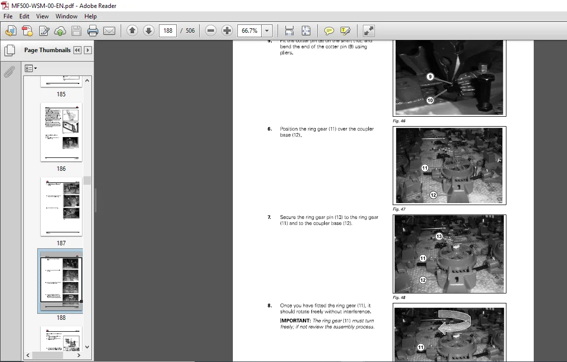
IMAGES PREVIEW OF THE MANUAL:
PLEASE NOTE:
- This is the same manual used by the dealers to diagnose and troubleshoot your vehicle
- You will be directed to the download page as soon as the purchase is completed. The whole payment and downloading process will take anywhere between 2-5 minutes
- Need any other service / repair / parts manual, please feel free to contact [email protected] . We still have 50,000 manuals unlisted
S.V