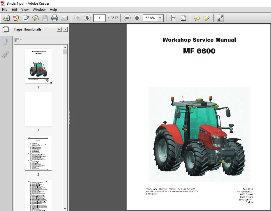
Massey Ferguson MF6600 Workshop Service Manual – PDF DOWNLOAD
Original price was: $67.95.$31.95Current price is: $31.95.
Massey Ferguson MF6600 Workshop Service Manual – PDF DOWNLOAD
Description
Massey Ferguson MF6600 Workshop Service Manual – PDF DOWNLOAD
DESCRIPTION:
Massey Ferguson MF6600 Workshop Service Manual – PDF DOWNLOAD
General:
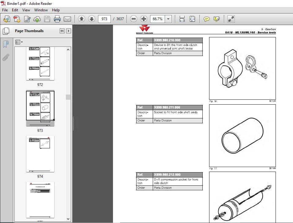
Service tools:
Repairs and parts replacement:
– Legislation in certain countries prohibits the fitting of parts that do not comply with the tractor manufacturer’s specifications
– Torque wrench setting figures given in the workshop manual must be strictly respected
– Locking devices must be fitted where specified. If the efficiency of a locking device is impaired during disassembly, it must be replaced.
MASSEY FERGUSON MF6600 WORKSHOP SERVICE MANUAL – PDF DOWNLOAD:
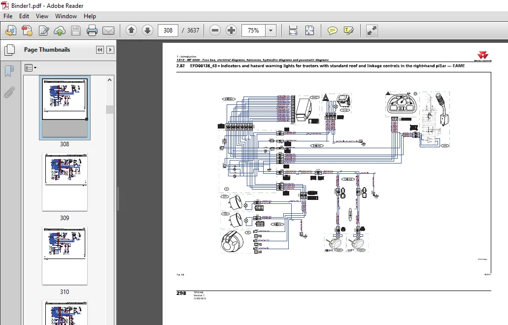
IMAGES PREVIEW OF THE MANUAL:
TABLE OF CONTENTS:
Massey Ferguson MF6600 Workshop Service Manual – PDF DOWNLOAD
Introduction
1A10 – General
1A11 – Error Codes
1A12 – Fuse Box, Electrical Diagrams, Harnesses, Hydraulics & Pneumatic Diagrams
1A16 – Adjustments, Bleeding, and Calibrations
Section 2 – Separation of Assemblies
2A17 – Front Linkage (Removing & Refitting)
2B17 – Front Axle (Removing & Refitting)
2C17 – Cooling Unit (Removing & Refitting)
2D17 – Front Frame (Removing & Refitting)
2E17 – Bonnet (Removing & Refitting)
2F17 – Engine (Removing & Refitting)
2G17 – Gearbox (Removing & Refitting)
2H17 – Cab (Removing & Refitting)
2I17 – Pedal Assembly (Removing & Refitting)
2J17 – Rear Axle (Removing & Refitting)
Section 3 – Engine
3A – Sisu Tier 4i Engine
3A11 – Error Codes
3A12 – Electrical & Hydraulic Diagrams
3A13 – Layout of Components
3A14 – Tests & Diagnostics
3A16 – Adjustments, Bleeding & Calibrations
3A17 – Disassembly & Reassembly
3B – e3 SCR Technology Engine
3B10 – General
3B12 – Electrical & Hydraulic Diagrams
3B13 – Layout of Components
3B17 – Disassembly & Reassembly
3B18 – Service Tools
Section 4 – Clutch
(Intentionally Left Blank)
Section 5 – Gearbox
5A – ML130 / ML160 Gearbox
5A10 – General
5A11 – Error Codes
5A12 – Electrical & Hydraulic Diagrams
5A13 – Layout of Components
5A14 – Tests & Diagnostics
5A16 – Adjustments, Bleeding & Calibrations
5A17 – Disassembly & Reassembly
5A18 – Service Tools
5C – GBA25 Gearbox & Variants
5C10 – General
5C11 – Error Codes
5C13 – Layout of Components
5C16 – Adjustments, Bleeding & Calibrations
5C17 – Disassembly & Reassembly
5C20 – GBA25 / PowerShuttle
5C20 – General
5C23 – Layout of Components
5C27 – Disassembly & Reassembly
5C28 – Service Tools
5C30 – GBA25 / Powershift Module
5C30 – General
5C33 – Layout of Components
5C37 – Disassembly & Reassembly
5C38 – Service Tools
5C40 – GBA25 / Robotic Mechanical Gearbox
5C40 – General
5C43 – Layout of Components
5C47 – Disassembly & Reassembly
5C48 – Service Tools
5C50 – GBA25 / Creeper Gears
5C50 – General
5C53 – Layout of Components
5C57 – Disassembly & Reassembly
5C60 – GBA25 / Super Creeper Gears
5C60 – General
5C63 – Layout of Components
5C67 – Disassembly & Reassembly
Section 6 – Rear Axle
HA130 / HA160 Axle & Braking
6A13 – Final Drives (Layout of Components)
6A17 – Final Drives (Disassembly & Reassembly)
6A21 – Differential (Error Codes)
6A22 – Differential (Electrical & Hydraulic Diagrams)
6A23 – Differential (Layout of Components)
6A26 – Differential (Adjustments, Bleeding & Calibrations)
6A27 – Differential (Disassembly & Reassembly)
6A31 – Tractor Braking (Error Codes)
6A32 – Tractor Braking (Electrical & Hydraulic Diagrams)
6A33 – Tractor Braking (Layout of Components)
6A36 – Tractor Braking (Adjustments, Bleeding & Calibrations)
6A37 – Tractor Braking (Disassembly & Reassembly)
6A51 – Hydraulic Trailer Braking (Error Codes)
6A52 – Hydraulic Trailer Braking (Electrical & Hydraulic Diagrams)
Pneumatic Trailer Braking (HA130/160)
General
Electrical & Hydraulic Diagrams
Layout of Components
Tests & Diagnostics
Adjustments, Bleeding & Calibrations
Disassembly & Reassembly
GPA20 Rear Axle & Systems
GPA20 – General
GPA20 – Layout of Components
(→ Subsections: Trumpet Housings, Differential, Tractor Braking, Trailer Braking, Hitch/Linkage, Auto-Hitch, Increased Capacity Linkage – each with General / Layout / Adjustments / Disassembly / Service Tools)
Section 7 – Power Take-Off (PTO)
HA130 / HA160 PTO
7A11 – Error Codes
7A12 – Electrical & Hydraulic Diagrams
7A13 – Layout of Components
7A16 – Adjustments, Bleeding & Calibrations
7A17 – Disassembly & Reassembly
GPA20 PTO
7C10 – General
7C20 – Intermediate Shaft, Driving Gear, PTO Brake – General
7C23 – Layout of Components
7C27 – Disassembly & Reassembly
GSPTO – General / Layout / Disassembly
Removable PTO Shaft – General / Layout / Disassembly
Shiftable PTO Shaft – General / Layout
Section 8 – Hydraulic Systems
(Detailed breakdown into HA130 LS system, GPA20 Load Sensing, Open Centre systems – each with General / Error Codes / Electrical & Hydraulic Diagrams / Layout / Tests / Adjustments / Disassembly / Service Tools)
Section 10 – Electricity
10A12 – Lighting & Equipment (Diagrams)
10B10 – Fuse Box (General)
10B12 – Fuse Box (Diagrams)
10C14 – Alternator (Tests & Diagnostics)
10C17 – Alternator (Disassembly & Reassembly)
10C18 – Alternator (Service Tools)
10D10 – Starter (General)
10D14 – Starter (Tests & Diagnostics)
10D17 – Starter (Disassembly & Reassembly)
10E17 – Triflash Triangle (Assembly)
Section 11 – Electronics
11A10 – MF 6600 List of All Components
Section 12 – Cab
Standard Air Conditioning
General / Diagrams / Layout / Tests / Adjustments / Disassembly
Self-Regulating Air Conditioning
General / Error Codes / Diagrams / Layout / Tests / Adjustments / Disassembly
Semi-Active Hydraulic Suspension
General / Diagrams / Layout / Adjustments / Disassembly
Section 13 – Accessories
Accessories Kits
Section 14 – Service Tools
14A01 – General
14A02 – Separation of Assemblies
14A03 – Engine
14A05 – Gearbox
14A06 – Rear Axle
14A07 – Power Take-Off
14A08 – Front Axle
14A09 – Hydraulics
14A10 – Electricity
14A11 – Electronics
14A12 – Cab
PLEASE NOTE:
- This is the SAME exact manual used by your dealers to fix your vehicle.
- The same can be yours in the next 2-3 mins as you will be directed to the download page immediately after paying for the manual.
- Any queries / doubts regarding your purchase, please feel free to contact [email protected]
S.V