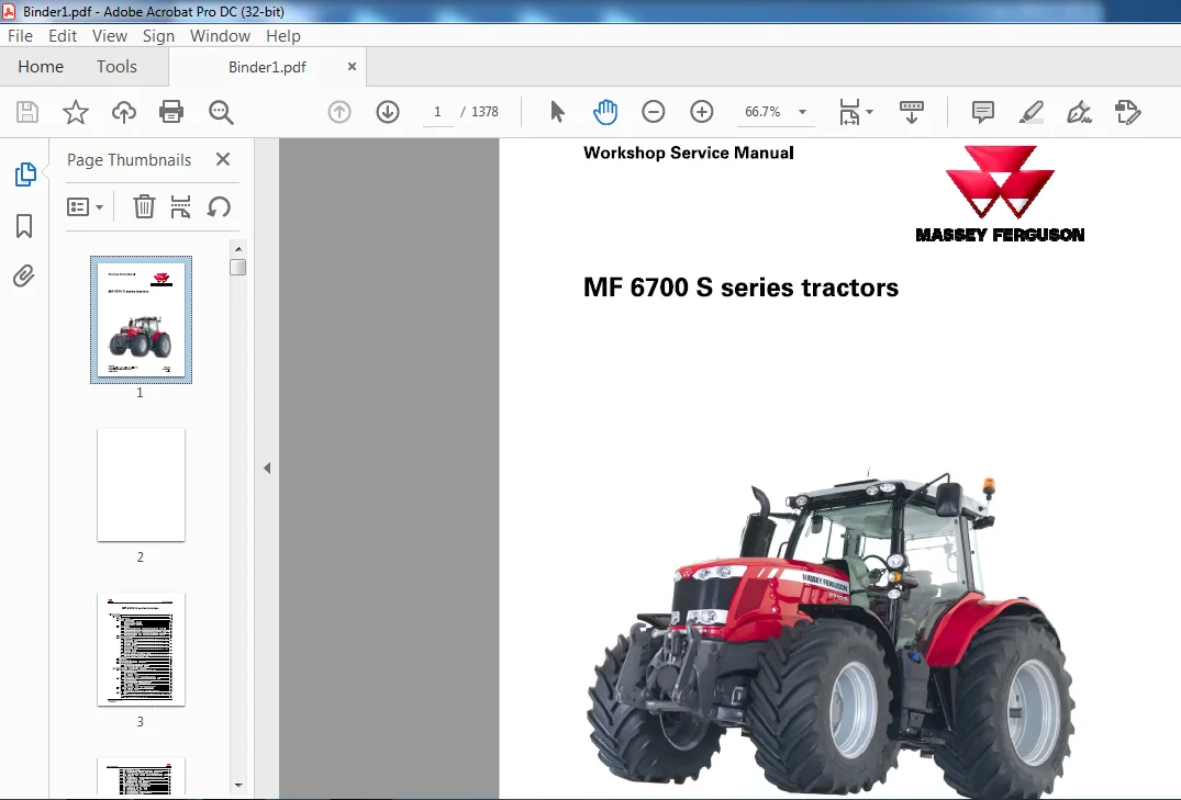
Massey Ferguson NA Tractor MF 6700 S Series Service Manual – PDF DOWNLOAD
Original price was: $67.95.$28.95Current price is: $28.95.
Massey Ferguson NA Tractor MF 6700 S Series Service Manual – PDF DOWNLOAD
Description
Massey Ferguson NA Tractor MF 6700 S Series Service Manual – PDF DOWNLOAD
DESCRIPTION:
Massey Ferguson NA Tractor MF 6700 S Series Service Manual – PDF DOWNLOAD
Part. No : ACT0025630
Using the manual
General
The purpose of this manual is to assist Dealers and Agents in the installation, servicing and repair of Massey Ferguson equipment. It is important to follow the methods shown and to use special tools in order to perform the operations within the times stated in the repair time schedule.
Structure of the manual:
For quick reference, each chapter starts with a table of contents, listing the various sections included in that chapter.
Service tools:
Where the use of a service tool is necessary to carry out an operation, the tool reference is mentioned with the relevant instruction. Tool drawings for makeshift tools are given at the end of the relevant sections.
Repairs and parts replacement
During replacement operations, using genuine Massey Ferguson parts is essential. Fitting parts other than genuine Massey Ferguson parts invalidates the tractor warranty and tractor safety may be compromised. All Massey Ferguson parts are guaranteed by the manufacturer. Massey Ferguson Dealers and Agents are required to supply genuine parts. For repairs and for fitting replacement parts and accessories, we draw your attention to the following points in particular:
• Legislation in certain countries prohibits the fitting of parts that do not comply with the tractor manufacturer’s specifications
• Torque wrench setting figures given in the workshop manual must be strictly respected
• Locking devices must be fitted where specified. If the efficiency of a locking device is impaired during disassembly, it must be replaced.
TABLE OF CONTENTS:
Massey Ferguson NA Tractor MF 6700 S Series Service Manual – PDF DOWNLOAD
1 Introduction 1-1
1 1 General 1-3
1 1 1 Using the manual 1-3
1 1 2 General specifications 1-3
1 1 2 1 MF 6700 S Dyna-4 tractors 1-3
1 1 2 2 MF 6700 S Dyna-6 tractors 1-1 2
1 1 2 3 MF 6700 S Dyna-VT tractors 1-2 1
1 1 3 Forward speeds 1-30
1 1 3 1 Forward speed with Dyna-4 40 kph transmission and 18 4R38 tires 1-30
1 1 3 2 Forward speed with Dyna-4 40 kph transmission and 20 8R38 tires 1-3 1
1 1 3 3 Forward speed with Dyna-6 40 kph ECO transmission and 20 8R38 tires 1-3 2
1 1 3 4 Forward speed with Dyna-6 50 kph transmission and 20 8R38 tires 1-3 4
1 1 3 5 Forward speed for all models with transmission in Dyna-VT mode 1-3 6
1 1 4 Dimensions and weights 1-3 7
1 1 5 Attachment points 1-4 1
1 1 5 1 Attachment points: MF 671 2 S / MF 671 3 S / MF 671 4 S Dyna-4/Dyna-6
models without front linkage 1-4 1
1 1 5 2 Attachment points: MF 671 2 S / MF 671 3 S / MF 671 4 S Dyna-4/Dyna-6
models with front linkage 1-4 3
1 1 5 3 Attachment points: MF 671 5 S / MF 671 6 S / MF 6718 S Dyna-4/Dyna-6
models without front linkage 1-4 5
1 1 5 4 Attachment points: MF 671 5 S/ MF 671 6 S / MF 6718 S Dyna-4/Dyna-6
models with front linkage 1-4 7
1 1 5 5 Attachment points: MF 671 3 S / MF 671 4 S / MF 671 5 S / MF 671 6 S /
MF 6718 S Dyna-VT models without front linkage: 1-4 9
1 1 5 6 Attachment points: MF 671 3 S / MF 671 4 S / MF 671 5 S / MF 671 6 S /
MF 6718 S Dyna-VT models with front linkage 1-5 1
1 1 6 Capacities 1-5 2
1 1 7 Conversion table 1-5 4
1 1 8 Retaining compounds and sealing products 1-5 5
1 1 9 Tightening torques 1-5 7
1 1 9 1 Tightening torques for screws and nuts 1-5 7
1 1 9 2 Tightening torques for hydraulic unions 1-61
1 2 Adjustments, bleeding and calibrations 1-65
1 2 1 Bleed operations: Dyna-VT -Assisted brake master cylinders 1-65
1 2 1 1 Charge connector 1-65
1 2 1 2 Pressure connector 1-65
1 2 1 3 Bleed screw locations 1-65
1 2 1 4 Procedure for bleeding the assisted braking system 1-66
1 2 2 Bleed operations: Dyna-4/Dyna-6 -Assisted brake master cylinders 1-68
1 2 2 1 Charge connector 1-68
1 2 2 2 Pressure connector – Load Sensing system 1-68
1 2 2 3 Pressure connector -Open Center system 1-68
1 2 2 4 Bleed screw locations 1-69
1 2 2 5 Procedure for bleeding the assisted braking system 1-70
1 2 3 Bleed operations: Dyna-4/Dyna-6 – High-pressure braking 1-72
1 2 3 1 Bleed screw locations 1-72
1 2 3 2 Procedure for bleeding the high-pressure braking system 1-73
1 2 4 Calibrations 1-74
1 2 4 1 Calibrating the automatic disengagement of the differential and 4-wheel
drive 1-74
1 2 4 2 Calibration of the forward-travel lever 1-76
MF 6700 S series tractors
ACT0025630
Table of contents
1 2 4 3 Forward speed calibration 1-7 9
1 2 4 4 Calibration of the Dyna-4 and Dyna-6 PowerShuttle transmission 1-7 9
1 2 4 5 Calibrating the power sensor on the Dyna-6 transmission 1-8 2
1 2 4 6 Dyna-VT transmission calibrations: Introduction and access t o calibration
using the instrument panel 1-8 3
1 2 4 7 Calibration of the high/low speed ranges (Hare /Tortoise) for Dyna-VT 1-8 4
1 2 4 8 Dyna-VT transmission calibration 1-85
1 2 4 9 Calibration of the Dyna-VT coupler function 1-86
1 2 4 10 Rear power take-off calibration for Dyna-VT 1-87
1 2 4 1 1 Front power take-off calibration for Dyna-VT 1-88
1 2 4 1 2 Dyna-VT transmission calibration error code 1-89
1 2 4 1 3 Calibration of the clutch pedal sensor 1-9 2
1 2 4 1 4 Calibration of the throttle pedal sensor 1-9 3
1 2 4 15 Calibrating the rear linkage 1-9 3
1 2 4 1 6 Calibration of the front linkage position sensor 1-9 5
1 2 4 1 7 Calibrate the suspended front axle 1-9 6
1 2 4 1 8 Calibrations to be carried out using the diagnostic tool 1-9 8
2 Separation of assemblies 2-1
2 1 Front linkage 2-3
2 1 1 Removal/refitting 2-3
2 2 Front axle 2-6
2 2 1 Removal/refitting 2-6
2 3 Cooling unit 2-8
2 3 1 Removal/refitting 2-8
2 4 Front frame 2-10
2 4 1 Removal/refitting 2-10
2 5 Engine cover 2-14
2 5 1 Removal/refitting 2-1 4
2 6 Engine 2-16
2 6 1 Removing and refitting the engine 2-1 6
2 6 2 Reassembling the engine flywheel 2-2 0
2 7 Operator environment 2-22
2 7 1 Removal/refitting 2-2 2
3 Engine 3-1
3 1 Tier 4F/Stage IV SCR Technology engine 4 cylinders 3-3
3 1 1 General 3-3
3 1 1 1 Notice to the technician 3-3
3 1 1 2 Safety instructions 3-3
3 1 1 3 Description of engine types 3-4
3 1 1 4 Location of the engine serial number 3-4
3 1 1 5 Lifting the engine 3-5
3 1 2 Principles of operation 3-6
3 1 2 1 General operating diagram 3-6
3 1 2 2 Mechanical part 3-7
3 1 2 3 Exhaust and intake system 3-9
3 1 2 4 Cooling system 3-1 1
3 1 2 5 Lubrication system 3-1 2
3 1 2 6 Fuel system 3-1 3
3 1 2 7 Electric control circuit 3-1 4
3 1 2 8 CC V system 3-15
3 1 3 Layout of components 3-1 6
3 1 3 1 Layout of components in the VRT engine compartment 3-1 6
3 1 4 Tests and diagnostics 3-1 7
3 1 4 1 Measuring the engine oil pressure 3-17
MF 6700 S series tractors
ACT0025630
Table of contents
3 1 5 Adjustments, bleeding and calibrations 3-18
3 1 5 1 Adjustments 3-18
3 1 5 2 Bleeding 3-1 9
3 1 6 Disassembly/reassembly 3-2 0
3 1 6 1 AGCO Power Workshop Service Manual 3-2 0
3 1 7 Service tools 3-2 0
3 1 7 1 General 3-2 0
3 1 7 2 Cylinder block tools 3-2 0
3 1 7 3 Timing gear and flywheel housing tools 3-2 1
3 1 7 4 Cylinder head and valve mechanism tools 3-2 2
3 1 7 5 Crank mechanism tools 3-2 3
3 1 7 6 Coolant pump tools 3-2 4
3 1 7 7 Engine control system tools 3-2 5
3 1 7 8 Maintenance and troubleshooting tools 3-2 5
3 2 SCR Technology 3-27
3 2 1 General 3-2 7
3 2 1 1 Notice to the technician 3-2 7
3 2 1 2 Safety instructions for DEF or AdBlue™ Identification of hazards 3-28
3 2 1 3 Abbreviations or terms used 3-3 1
3 2 2 Principles of operation 3-3 1
3 2 2 1 Principles of operation 3-3 1
3 2 2 2 Architecture of the VRT 4-cylinder SCR Technology system 3-3 5
3 2 3 Schematic diagrams 3-3 6
3 2 3 1 VRT 4-cylinder SCR Technology system schematic diagram 3-3 6
3 2 4 Layout of components 3-38
3 2 4 1 SCR Technology components for VRT engine 3-38
3 2 5 Disassembly/reassembly 3-4 0
3 2 5 1 Removing the metering module 3-4 0
3 2 5 2 Injector 3-4 2
3 2 5 3 Coolant solenoid valve 3-4 4
3 2 5 4 DEF or AdBlue™ tank 3-4 5
3 2 5 5 Removing the DEF or AdBlue™ gage 3-4 7
3 2 5 6 Catalytic converter or DOC (catalyseur d’oxydation diesel) 3-48
3 2 6 Service tools 3-4 9
3 2 6 1 General 3-4 9
3 2 6 2 3rd generation SCR engine -SeNice tools 3-4 9
4 Clutch 4-1
4 1 Chapter not used for this model 4-3
5 Gearbox 5-1
5 1 ML140 5-5
5 1 1 General 5-5
5 1 1 1 General 5-5
5 1 1 2 Transmission operating principle 5-5
5 1 1 3 Transmission operating principle diagram 5-9
5 1 1 4 Forward/reverse high-pressure relief valves 5-15
5 1 1 5 Control spool valve 5-1 7
5 1 1 6 Flushing valve 5-2 0
5 1 2 Layout of components 5-2 3
5 1 2 1 Gearbox main components -parts list 5-2 3
5 1 2 2 Gearbox main components -diagram 5-2 4
5 1 3 Tests and diagnostics 5-2 5
5 1 3 1 Hydraulic tests 5-2 5
5 1 4 Disassembly/reassembly 5-3 5
5 1 4 1 Disassembling the Dyna-VT module 5-3 5
5 1 4 2 Reassembling the Dyna-VT unit 5-4 3
MF 6700 S series tractors
ACT0025630
Table of contents
5 1 4 3 Filling the gearbox 5-5 4
5 1 4 4 Removing/refitting forward ( 2 V 3) /reverse ( 2 V 4) high-pressure relief valves
5-5 5
5 1 4 5 Removing/refitting the flushing valve 5-5 6
5 1 5 Service tools 5-5 6
5 1 5 1 General 5-5 6
5 1 5 2 ML 1 3 0 /M L 1 4 0 /M L 1 6 0 /M L 180 -Service tools 5-5 7
5 2 GBA25/General 5-67
5 2 1 General 5-6 7
5 2 2 Principles of operation 5-7 0
5 2 2 1 Construction and description 5-7 0
5 2 2 2 Kinematics of the Dyna-4 GBA 2 5 gearbox 5-7 5
5 2 2 3 Kinematics of the Dyna-6 GBA 2 5 gearbox 5-7 8
5 2 2 4 Synchronisers 5-8 1
5 2 2 5 Main gearbox robotic control 5-8 3
5 2 3 Layout of components 5-85
5 2 3 1 View of Dyna-4 GBA 2 5 gearbox assembly 5-85
5 2 3 2 View of Dyna-4 GBA 2 5 gearbox assembly 5-87
5 2 3 3 View of Dyna-6 GBA 2 5 gearbox assembly 5-89
5 2 3 4 View of Dyna-6 GBA 2 5 gearbox assembly 5-9 1
5 2 3 5 Dyna-4 GBA 2 5 gearbox specifications 5-9 3
5 2 3 6 Dyna-6 GBA 2 5 gearbox specifications 5-9 4
5 2 3 7 GBA 2 5 gearbox specifications 5-95
5 2 4 Disassembly/reassembly 5-9 7
5 2 4 1 Dyna-4 GBA 2 5 gearbox disassembly 5-9 7
5 2 4 2 Dyna-6 GBA 2 5 gearbox disassembly 5-10 2
5 2 4 3 Synchronizers 5-10 6
5 3 GBA25/Power5huttle 5-109
5 3 1 General 5-10 9
5 3 2 Principles of operation 5-10 9
5 3 3 Layout of components 5-1 1 3
5 3 3 1 View of the GBA 2 5 PowerShuttle assembly 5-1 1 3
5 3 3 2 Blown-up view of the GBA 2 5 PowerShuttle 5-1 15
5 3 4 Disassembly/reassembly 5-1 1 7
5 3 4 1 Dyna-4 transmission 5-1 1 7
5 3 4 2 Dyna-6 transmission 5-1 2 2
5 3 4 3 Disassembling the PowerShuttle 5-1 2 7
5 3 4 4 Reassembling the PowerShuttle 5-1 2 9
5 3 4 5 Final steps 5-1 3 1
5 3 5 Service tools 5-1 3 1
5 3 5 1 General 5-1 3 1
5 3 5 2 PowerShuttle -Service tools 5-1 3 1
5 4 GBA25/Dyna-4 PowerShift module 5-132
5 4 1 Dyna-4 General information 5-1 3 2
5 4 2 Dyna- 4 Operating principle 5-1 3 2
5 4 2 1 Kinematics 5-1 3 4
5 4 3 Layout of components 5-1 4 1
5 4 3 1 View of Dyna-4 assembly 5-1 4 1
5 4 3 2 Dyna-4 blown-up view 5-1 4 3
5 4 4 Removing/refitting Dyna-4 5-1 4 5
5 4 4 1 Preliminary steps 5-1 4 5
5 4 4 2 Removing the Dynashift module 5-1 4 5
5 4 4 3 Refitting the Dynashift module 5-1 4 7
5 4 4 4 Disassembling the Dynashift module 5-1 4 8
5 4 4 5 Reassembling the Dynashift module 5-15 3
5 4 4 6 Disassembling the planet gears 5-15 7
5 4 4 7 Reassembling the planet gears 5-15 8
MF 6700 S series tractors
ACT0025630
Table of contents
5 4 4 8 Final steps 5-15 9
5 4 5 Service tools 5-1 6 0
5 4 5 1 General 5-1 6 0
5 4 5 2 Powershift module -Service tools 5-1 6 0
5 5 GBA25/Dyna-6 PowerShift module 5-161
5 5 1 Dyna-6 -General information 5-1 6 1
5 5 2 Dyna-6 Operating principle 5-1 6 1
5 5 2 1 Kinematics 5-1 6 3
5 5 3 Layout of components 5-1 7 1
5 5 3 1 View of Dyna-6 assembly 5-1 7 1
5 5 3 2 Dyna-6 blown-up view 5-1 7 3
5 5 4 Removing/refitting Dyna-6 5-1 7 5
5 5 4 1 Preliminary steps 5-1 7 5
5 5 4 2 Removing the Powershift module 5-1 7 5
5 5 4 3 Refitting the Powershift module 5-1 7 7
5 5 4 4 Disassembling the Dynashift module 5-1 7 8
5 5 4 5 Reassembling the Dynashift module 5-1 8 2
5 5 4 6 Disassembling the multiplier module 5-1 85
5 5 4 7 Reassembling the multiplier module 5-1 86
5 5 4 8 Disassembling the planet gears 5-1 89
5 5 4 9 Reassembling the planet gears 5-1 89
5 5 4 10 Final steps 5-1 9 0
5 5 5 Service tools 5-1 9 1
5 5 5 1 General 5-1 9 1
5 5 5 2 Powershift module -Service tools 5-1 9 1
5 6 GBA25/Robotic mechanical gearbox 5-193
5 6 1 General 5-1 9 3
5 6 2 Principles of operation 5-1 9 3
5 6 2 1 Description and kinematics of ratios 5-1 9 5
5 6 3 Layout o f components 5-1 9 9
5 6 3 1 View of the primary and secondary shaft assembly 5-1 9 9
5 6 3 2 View of the reverse layshaft and synchroniser control assembly 5-2 0 2
5 6 3 3 Blown-up view of the robotic mechanical gearbox 5-2 0 4
5 6 4 Disassembly/reassembly 5-2 0 7
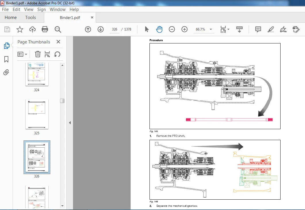
5 6 4 1 Preliminary steps 5-2 0 7
5 6 4 2 Removing the primary and secondary shafts 5-2 0 7
5 6 4 3 Refitting the primary and secondary shafts 5-2 10
5 6 4 4 Disassembling the primary and secondary shafts 5-2 1 2
5 6 4 5 Reassembling the primary and secondary shafts 5-2 15
5 6 4 6 Shimming the primary and secondary shafts in the housing 5-2 1 9
5 6 4 7 Adjusting the selector rails and forks 5-2 2 1
5 6 4 8 Adjusting the interlock mechanism 5-2 2 5
5 6 4 9 Final steps 5-2 2 6
5 6 5 Service tools 5-2 2 7
5 6 5 1 General 5-2 2 7
5 6 5 2 Robotic mechanical gearbox -Service tools 5-2 2 7
5 7 GBA25/Super creeper gears 5-228
5 7 1 General 5-2 2 8
5 7 2 Principles of operation 5-2 2 9
5 7 3 Layout of components 5-2 3 2
5 7 3 1 View of the assembly 5-2 3 2
5 7 3 2 Blown-up view 5-2 3 3
5 7 4 Disassembly/reassembly 5-2 3 4
5 7 4 1 Removing/refitting and disassembling/reassembling the epicyclic gear
trains 5-2 3 4
5 7 4 2 Disassembling the input planet carrier 5-2 3 5
5 7 4 3 Reassembling the input planet carrier 5-2 3 6
MF 6700 S series tractors
ACT0025630
Table of contents
5 7 4 4 Disassembling the output planet carrier 5-2 3 7
5 7 4 5 Reassembling the output planet carrier 5-2 3 8
5 7 4 6 Final steps 5-2 4 0
5 7 4 7 Adjusting the control 5-2 4 0
6 Rear Axle 6-1
6 1 HA140 6-7
6 1 1 General 6-7
6 1 1 1 General 6-7
6 1 1 2 Principles of operation 6-7
6 1 1 3 Schematic diagram 6-8
6 1 2 Layout of components 6-9
6 1 2 1 Rear axle main components 6-9
6 1 3 Disassembly/reassembly 6-10
6 1 3 1 Cross section view of the rear axle 6-10
6 2 HA140/Final drives 6-11
6 2 1 General 6-1 1
6 2 2 Layout of components 6-1 3
6 2 2 1 Cross-section view of a final drive unit 6-1 3
6 2 3 Disassembly/reassembly 6-15
6 2 3 1 Removing a final drive unit 6-15
6 2 3 2 Refitting a final drive unit 6-15
6 2 4 Service tools 6-15
6 2 4 1 General 6-15
6 2 4 2 Final drives -Service tools 6-1 6
6 3 HA140/Differential 6-18
6 3 1 General 6-1 8
6 3 1 1 General 6-1 8
6 3 1 2 Principles of operation 6-1 8
6 3 1 3 Schematic diagram 6-2 0
6 3 2 Layout of components 6-2 1
6 3 2 1 Cross section view of the differential 6-2 1
6 3 2 2 Blown-up view of the pinion 6-2 2
6 3 2 3 Blown-up view of the differential 6-2 3
6 3 3 Disassembly/reassembly 6-2 4
6 3 3 1 Removing the differential 6-2 4
6 3 3 2 Refitting the differential 6-2 7
6 3 3 3 Disassembling the pinion 6-3 5
6 3 3 4 Reassembling the pinion 6-4 1
6 3 3 5 Disassembling the differential 6-4 9
6 3 3 6 Reassembling the differential 6-5 5
6 3 4 Service tools 6-6 2
6 3 4 1 General 6-6 2
6 3 4 2 Differential -Service tools 6-6 3
6 4 HA140/Tractor braking 6-66
6 4 1 General 6-6 6
6 4 1 1 General 6-6 6
6 4 1 2 Principles of operation 6-6 7
6 4 1 3 Hydraulic assistance 6-6 9
6 4 2 Layout of components 6-7 0
6 4 2 1 Blown-up view o f the rear axle brake system 6-7 0
6 4 2 2 Layout of components 6-7 1
6 4 3 Adjustments, bleeding and calibrations 6-7 3
6 4 3 1 Adjustments 6-7 3
6 4 3 2 Bleeding 6-7 5
6 4 4 Disassembly/reassembly 6-7 9
6 4 4 1 Removing the rear axle brakes 6-7 9
MF 6700 S series tractors
ACT0025630
Table of contents
6 4 4 2 Assembling the rear axle brakes 6-8 3
6 4 4 3 Removing/refitting the assisted-brake master cylinders 6-88
6 4 5 Service tools 6-9 1
6 4 5 1 General 6-9 1
6 4 5 2 Tractor braking -Service tools 6-9 1
6 5 HA140/Hydraulic trailer braking 6-93
6 5 1 General 6-9 3
6 5 1 1 Trailer brake unit 6-9 3
6 5 2 Hydraulic test 6-9 4
6 6 GPA20 – General 6-96
6 6 1 General 6-9 6
6 6 2 Principles of operation 6-9 6
6 6 3 Layout of components 6-9 7
6 6 3 1 Center housing assembly (longitudinal cross-section) 6-9 7
6 6 3 2 Center housing assembly (transverse cross-section) 6-9 8
6 7 GPA20/Heavy Duty and Heavy Duty+ final drives 6-99
6 7 1 General 6-9 9
6 7 1 1 General 6-9 9
6 7 1 2 Principles of operation 6-9 9
6 7 2 Layout of components 6-10 1
6 7 2 1 View of the assembly 6-10 1
6 7 2 2 Blown-up view 6-10 3
6 7 3 Disassembly/reassembly 6-10 5
6 7 3 1 Removing/refitting a final drive 6-10 5
6 7 3 2 Removing/refitting and disassembling/reassembling a planet carrier 6-10 6
6 7 3 3 Replacing tapered roller bearings and seals 6-10 9
6 7 3 4 Shimming the tapered roller bearings of the axle shaft 6-1 1 2
6 7 3 5 Replacing a wheel stud 6-1 1 6
6 7 4 Service tools 6-1 1 6
6 7 4 1 General 6-1 1 6
6 7 4 2 G PA20 /Final drives -Service tools 6-1 1 7
6 8 GPA20/Super Heavy Duty final drives 6-118
6 8 1 General 6-1 1 8
6 8 1 1 General 6-1 1 8
6 8 1 2 Principles of operation fl-1 18
6 8 2 Layout of components 6-1 1 9
6 8 2 1 View of the assembly 6-1 1 9
6 8 2 2 Blown-up view 6-1 2 1
6 8 3 Disassembly/reassembly 6-1 2 3
6 8 3 1 Removing/refitting a final drive 6-1 2 3
6 8 3 2 Disassembling/reassembling the planet carrier 6-1 2 4
6 8 3 3 Fitting and shimming the tapered roller bearings of the axle shaft 6-1 2 6
6 8 3 4 Replacing a wheel stud 6-1 2 8
6 8 4 Service tools 6-1 2 9
6 8 4 1 General 6-1 2 9
6 8 4 2 GPA 20 /Final drives -Service tools 6-1 2 9
6 9 GPA20/Differential 6-130
6 9 1 General 6-1 30
6 9 2 Layout of components 6-1 3 1
6 9 2 1 View of the assembly 6-1 3 1
6 9 2 2 Blown-up view 6-1 3 3
6 9 3 Disassembly/reassembly 6-1 3 5
6 9 3 1 Removing the left-hand flange and differential lock assembly 6-1 3 5
6 9 3 2 Disassembling and reassembling the differential lock assembly fl-1 3 6
6 9 3 3 Refitting the left-hand flange and the differential lock assembly 6-1 3 7
6 9 3 4 Removing the differential assembly 6-1 3 8
6 9 3 5 Disassembling the differential assembly and the crown wheel 6-1 3 9
MF 6700 S series tractors
ACT0025630
Table of contents
6 9 3 6 Removing and disassembling the gear 6-140
6 9 3 7 Reassembling the crown wheel and the differential assembly 6-1 4 2
6 9 3 8 Adjusting the taper distance, refitting and shimming the gear 6-1 4 3
6 9 3 9 Refitting and shimming the differential assembly 6-1 4 7
6 9 3 10 Adjusting and checking the backlash 6-15 2
6 9 3 1 1 Final reassembly 6-15 6
6 9 4 Service tools 6-15 7
6 9 4 1 General 6-15 7
6 9 4 2 GPA 20 /Differential -Service tools 6-15 7
6 10 GPA20/Brake pistons 6-158
6 10 1 General 6-15 8
6 10 2 Principles of operation 6-15 8
6 10 3 Layout of components 6-15 9
6 10 3 1 View of the assembly 6-15 9
6 10 3 2 Blown-up view 6-1 60
6 10 4 Disassembly/reassembly 6-1 60
6 10 4 1 Disassembly 6-1 60
6 10 4 2 Reassembly 6-1 6 2
6 11 GPA20/Hand brake unit and control 6-165
6 1 1 1 General 6-1 6 5
6 1 1 2 Principles of operation 6-1 6 5
6 1 1 3 Layout of components 6-1 6 7
6 1 1 3 1 View of the assembly 6-1 6 7
6 1 1 3 2 Blown-up view -Three disks 6-1 6 9
6 1 1 4 Disassembly/reassembly 6-1 7 1
6 1 1 4 1 Disassembly 6-1 7 1
6 1 1 4 2 Reassembly 6-17 3
6 1 1 4 3 Fitting the control 6-17 8
6 1 1 4 4 Adjusting the control 6-17 8
6 12 GPA20/Tractor braking 6-180
6 1 2 1 Assisted brake master cylinders: 6-1 80
6 1 2 1 1 General 6-1 80
6 1 2 1 2 Principles of operation 6-1 8 1
6 1 2 1 3 Layout o f components 6-1 8 2
6 1 2 1 4 Removing/refitting the assisted-brake master cylinders 6-1 8 3
6 1 2 2 High-pressure braking 6-1 86
6 1 2 2 1 General 6-1 86
6 1 2 2 2 Principles of operation 6-1 87
6 1 2 2 3 Layout of components and designation of hydraulic ports in the highpressure
braking unit 6 -1 89
6 1 2 2 4 Decompressing the high-pressure braking system 6-1 90
6 1 2 2 5 Removing and refitting the high-pressure braking unit 6-1 90
6 1 2 3 Load Sensing trailer braking 6-1 9 2
6 1 2 3 1 General 6-1 9 2
6 1 2 3 2 Principles of operation 6-1 9 3
6 1 2 3 3 Schematic diagram 6-1 9 5
6 1 2 3 4 Identification o f 1 10 I/min Load Sensing ports 6-1 9 7
6 1 2 3 5 Removing and refitting the trailer braking unit 6-200
6 1 2 3 6 Plug tightening torques in the event of maintenance on the spools ( 2) ( 6)
6-20 3
6 1 2 4 Open Center trailer braking 6-20 3
6 1 2 4 1 General 6-20 3
6 1 2 4 2 Principles of operation 6-20 4
6 1 2 4 3 Identification of pipes, hoses and ports 6-20 7
6 1 2 4 4 Identification of channels 6-20 8
6 1 2 4 5 Removing and refitting the brake spool valve 6-20 9
6 1 2 5 Adjustments, bleeding and calibrations 6-2 10
MF 6700 S series tractors
ACT0025630
Table of contents
6 1 2 5 1 Assisted brake master cylinders: 6-2 10
6 1 2 5 2 High-pressure braking 6-2 1 4
6 1 2 5 3 Pedals 6-2 1 6
6 1 2 6 Service tools 6-2 1 7
6 1 2 6 1 General 6-2 1 7
6 1 2 6 2 Tractor braking -Service tools 6-2 1 7
6 13 GPA20/Hitch/Linkage 6-218
6 1 3 1 Linkage -General 6-2 1 8
6 1 3 2 Hitch -General 6-2 1 8
6 1 3 3 Layout of components 6-2 1 9
6 1 3 3 1 View of the assembly 6-2 1 9
6 1 3 3 2 Blown-up view 6-2 2 1
6 1 3 4 Adjustments, bleeding and calibrations 6-2 2 3
6 1 3 4 1 Adjusting the angular position sensor 6-2 2 3
6 1 3 5 Disassembly/reassembly 6-2 2 4
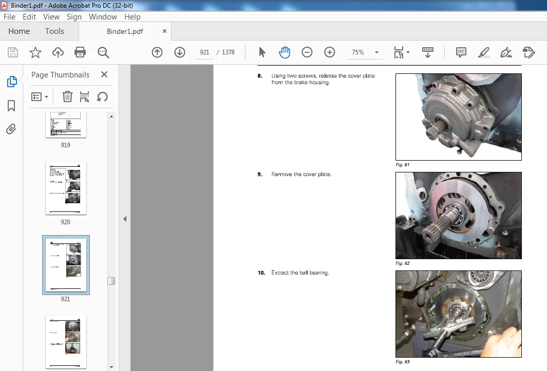
6 1 3 5 1 Removing the linkage cover plate 6-2 2 4
6 1 3 5 2 Disassembling the linkage cover plate 6-2 2 7
6 1 3 5 3 Reassembling the linkage cover plate 6 -2 2 8
6 1 3 5 4 Shimming the linkage shaft 6-2 3 0
6 1 3 5 5 Refitting the linkage cover plate 6-2 3 0
6 1 3 5 6 Disassembling and reassembling a lift ram 6-2 3 1
6 14 GPA20+/Hitch/lncreased capacity linkage – General 6-233
6 1 4 1 Linkage -General 6-2 3 3
6 1 4 2 Hitch -General 6-2 3 4
6 1 4 3 Layout of components 6-2 3 5
6 1 4 3 1 View of the assembly 6-2 3 5
6 1 4 3 2 Blown-up view 6-2 3 7
6 1 4 4 Adjustments, bleeding and calibrations 6-2 3 9
6 1 4 4 1 Adjusting the angular position sensor 6-2 3 9
6 1 4 4 2 Adjusting the forward speed sensor 6-2 4 3
6 1 4 5 Disassembly/reassembly 6-2 4 4
6 1 4 5 1 Removing and refitting the increased capacity linkage cover plate 6-2 4 4
6 1 4 5 2 Removing and refitting the increased capacity linkage cover plate 6-2 4 8
6 1 4 5 3 Shimming the linkage shaft 6-2 5 6
6 1 4 5 4 Disassembling and reassembling a lift ram 6-2 5 8
6 1 4 6 Service tools 6-2 6 0
6 1 4 6 1 General 6-2 6 0
6 1 4 6 2 GPA 2 0 + /Hitch/Increased capacity linkage -Service tools 6-2 6 0
6 15 Pneumatic trailer braking 6-261
6 15 1 General 6-2 6 1
6 15 1 1 GPA 2 0 / 2 0 + 6 -2 6 1
6 15 1 2 GPA4 0 and HA 1 4 0 / 1 80 6-2 6 5
6 15 2 Layout of components 6-2 7 1
6 15 3 Test and diagnostics 6-2 7 2
6 15 3 1 Pneumatic system test 6-2 7 2
6 15 3 2 Sealing test on the pneumatic system 6-2 7 4
6 15 4 Adjustments, bleeding and calibrations 6-2 7 4
6 15 4 1 Adjusting the pressure relief valve 6-2 7 4
6 15 4 2 Adjusting the hand brake rod 6-2 7 6
6 15 5 Disassembly/reassembly 6-2 7 7
6 15 5 1 General 6-2 7 7
6 15 5 2 Compressor 6-2 7 7
6 15 6 Service tools 6-2 7 9
6 15 6 1 General 6-2 7 9
6 15 6 2 Pneumatic trailer brake – Service tools 6-2 7 9
6 16 Auto-hitch 6-282
6 1 6 1 General 6-2 8 2
M F 6700 S series tractors
ACT0025630
Table of contents
6 1 6 2 Principles of operation 6-2 8 2
6 1 6 3 Layout o f components 6-2 8 3
6 1 6 3 1 Blown-up view 6-2 8 3
6 1 6 4 Adjustments, bleeding and calibrations 6-2 8 4
6 1 6 4 1 Adjusting the tie rods and the control 6-2 8 4
6 1 6 5 Disassembly/reassembly 6-2 86
6 1 6 5 1 Refitting the frame 6-2 86
6 17 Rear wheels/hubs 6-288
6 17 1 General 6-2 88
6 1 7 2 Disassembly/reassembly 6-2 9 1
6 17 2 1 Flanged axle shaft 6-2 9 1
6 17 2 2 Straight axle shaft 6-2 9 4
6 17 2 3 Adjusting the rear wheel track width 6-2 9 6
6 17 2 4 Fitting the rear wheel weights 6-3 0 0
7 Power take-off 7-1
7 1 HA140 7-3
7 1 1 General 7-3
7 1 2 Principles of operation 7-4
7 1 3 Layout of components 7-7
7 1 3 1 Cross-section view 7-7
7 1 4 Disassembly/reassembly 7-9
7 1 4 1 Disassembling/reassembling the PTO clutch 7-9
7 1 4 2 Disassembling the PTO shafts 7-1 3
7 1 4 3 Reassembling the PTO shafts 7-1 7
7 2 GPA20 7-22
7 2 1 General 7-2 2
7 2 2 Principles of operation 7-2 3
7 3 GPA20/Clutch 7-30
7 3 1 General 7-3 0
7 3 2 Principles of operation 7-3 0
7 3 3 Layout of components 7-3 2
7 3 3 1 Parts list 7-3 2
7 3 3 2 Blown-up view 7-3 4
7 3 4 Layout of components 7-3 5
7 3 4 1 View of the assembly 7-3 5
7 3 5 Disassembly/reassembly 7-3 7
7 3 5 1 Removing and refitting the PTO clutch 7-3 7
7 3 5 2 Disassembling/reassembling the clutch 7-3 8
7 3 6 Service tools 7-4 0
7 3 6 1 General 7-4 0
7 3 6 2 GPA 2 0 /Clutch -Service tools 7-4 1
7 4 GPA20/lntermediate shaft/Drive gear/PTO brake 7-42
7 4 1 General 7-4 2
7 4 2 Principles of operation 7-4 2
7 4 3 Layout of components 7-4 4
7 4 3 1 Power take-off (PTO) parts list 7-4 4
7 4 3 2 Exploded view ( 2-speed version) 7-4 5
7 4 3 3 Overview ( 2-speed version) 7-4 5
7 4 3 4 Exploded view ( 4-speed version) 7-4 6
7 4 3 5 Assembly view ( 4-speed version) 7-4 7
7 4 4 Disassembly/reassembly 7-4 7
7 4 4 1 Removing and refitting the upper shaftline ( 2-speed version) 7-4 7
7 4 4 2 Removing/refitting the driving gears ( 4-speed version) 7-4 9
7 4 4 3 Shimming the driving gear 7-5 2
7 4 4 4 Adjustment of the control ( 4-speed version) 7-5 3
7 5 GPA20/Output shaft without speed selection 7-55
MF 6700 S series tractors
ACT0025630
Table of contents
7 5 1 General 7-5 5
7 5 2 Layout of components 7-5 5
7 5 2 1 View of the assembly 7-5 5
7 5 2 2 Blown-up view 7-5 6
7 5 3 Disassembly/reassembly 7-5 7
7 5 3 1 Removing/refitting the rear bearing 7-5 7
7 5 3 2 Disassembling and reassembling the gears 7-5 8
7 6 GPA20/Output shaft with speed selection 7-60
7 6 1 General 7-6 0
7 6 2 Layout of components 7-6 0
7 6 2 1 Power take-off (PTO) parts list 7-6 0
7 6 2 2 View of the assembly 7-6 2
7 6 2 3 Blown-up view 7-6 5
7 6 3 Disassembly/reassembly 7-6 6
7 6 3 1 Removing/refitting the rear bearing 7-6 6
7 6 3 2 Disassembling and reassembling the gears 7-6 7
7 6 3 3 Shimming the shaft with reinforced sealing 7-7 0
7 6 3 4 Adjusting the control 7-7 0
7 7 GPA20/PTO electrohydraulic controls 7-72
7 7 1 General 7-7 2
7 7 2 Principles of operation 7-7 2
7 7 3 Layout of components 7-7 4
7 7 3 1 View of the assembly 7-7 4
7 7 3 2 Blown-up view 7-7 5
7 7 4 Disassembly/reassembly 7-7 5
7 7 4 1 Removing/refitting the 5 4 0 / 10 0 0 control 7-7 5
7 7 4 2 Removing/refitting the Standard/Economy control 7-7 7
7 8 GPA20/GSPTO 7-79
7 8 1 General 7-7 9
7 8 2 Principles of operation 7-7 9
7 8 3 Layout of components 7-80
7 8 3 1 View of the assembly 7-80
7 8 3 2 Blown-up view 7-8 1
7 8 4 Disassembly/reassembly 7-8 1
7 8 4 1 Disassembling and reassembling the PTO 7-8 1
7 8 4 2 Assembling and adjusting the control 7-8 4
7 9 Zuidberg front power take-off 7-87
7 9 1 General 7-87
7 9 1 1 General 7-87
7 9 1 2 Principles of operation 7-87
7 9 1 3 Schematic diagrams 7-90
7 9 2 Layout of components 7-9 1
7 9 2 1 Blown-up view of the PTO unit 7-9 1
7 9 2 2 Blown-up view of the hydraulic pump and the PTO clutch 7-9 2
7 9 2 3 Blown-up view of the drive shaft and the oil cooler 7-9 3
7 9 3 Tests and diagnostics 7-9 4
7 9 3 1 Hydraulic tests 7-9 4
7 9 3 2 Electrical tests 7-95
7 9 4 Adjustments, bleeding and calibrations 7-9 5
7 9 4 1 Draining and changing the filter 7-95
7 9 5 Disassembly/reassembly 7-9 6
7 9 5 1 Removing and refitting the front power take-off unit 7-9 6
7 9 5 2 Disassembling and reassembling the front power take-off unit 7-9 7
8 Front axle 8-1
8 1 DANA 735 front axle 8-3
8 1 1 General 8-3
MF 6700 S series tractors
ACT0025630
Table of contents
8 1 1 1 DANA General 8-3
8 1 1 2 Principles of operation 8-3
8 1 1 3 DANA front axle 7 4 0 / 5 2 8-5 2 9-5 3 0-6 1 3-6 1 4-6 15 Dimensions –
Specifications -Identification 8-4
8 1 1 4 Topping up and checking levels 8-7
8 1 2 Layout of components 8-8
8 1 2 1 Layout of front axle components 8-8
8 1 2 2 View of front axle assembly 8-10
8 1 3 Tests and diagnostics 8-1 2
8 1 3 1 Troubleshooting 8-1 2
8 1 4 Disassembly/reassembly 8-1 4
8 1 4 1 DANA 7 3 5 tightening torques 8-1 4
8 1 4 2 DANA Workshop Service Manuals 8-1 6
8 2 DANA 740 front axle 8-17
8 2 1 General 8-1 7
8 2 1 1 DANA General 8-1 7
8 2 1 2 Principles of operation 8-1 7
8 2 1 3 DANA front axle 7 4 0 / 5 5 3-5 5 4-6 1 4-6 15- Dimensions – Specifications –
Identification 8-1 8
8 2 1 4 Topping up and checking levels 8-2 1
8 2 2 Layout of components 8-2 2
8 2 2 1 Layout of front axle components 8-2 2
8 2 2 2 View of front axle assembly 8-2 4
8 2 3 Tests and diagnostics 8-2 6
8 2 3 1 Troubleshooting 8-2 6
8 2 4 Disassembly/reassembly 8-2 8
8 2 4 1 DANA 7 4 0 tightening torques 8-2 8
8 2 4 2 DANA Workshop Service Manuals 8-3 0
8 3 HA140/4-wheel drive clutch 8-31
8 3 1 General 8-3 1
8 3 1 1 General – 4-wheel drive clutch 8-3 1
8 3 1 2 Four-wheel drive function operating principles 8-3 1
8 3 2 Layout of components 8-3 3
8 3 2 1 Cross-section view of the 4-wheel drive clutch 8-3 3
8 3 2 2 Blown-up view of the 4-wheel drive clutch 8-3 4
8 3 3 Disassembly/reassembly 8-3 5
8 3 3 1 Disassembling the 4WD clutch 8-3 5
8 3 3 2 Reassembling the 4WD clutch 8-3 9
8 4 HA140/Universal joint shaft brake 8-46
8 4 1 Layout of components 8-4 6
8 4 1 1 Cross-section view of the universal j oint shaft brake 8-4 6
8 4 1 2 Exploded view of the universal j oint shaft brake 8-4 7
8 4 2 Disassembly/reassembly 8-4 7
8 4 2 1 Disassembling the universal joint shaft brake 8-4 7
8 4 2 2 Reassembling the universal j oint shaft brake 8-5 2
8 5 GPA20/4-wheel drive clutch 8-59
8 5 1 General 8-5 9
8 5 2 Principles of operation 8-5 9
8 5 3 Layout of components 8-6 0
8 5 3 1 View of the assembly 8-6 0
8 5 3 2 Blown-up view 8-6 2
8 5 4 Disassembly/reassembly 8-6 3
8 5 4 1 Removing the clutch assembly 8-6 3
8 5 4 2 Disassembling the clutch 8-6 5
8 5 4 3 Reassembling the clutch 8-6 6
8 5 4 4 Refitting the clutch assembly 8-6 7
8 5 5 Service tools 8-6 9
MF 6700 S series tractors
ACT0025630
Table of contents
8 5 5 1 General 8-6 9
8 5 5 2 4-wheel drive clutch -Service tools 8-6 9
8 6 Steering unit/Closed Center 8-71
8 6 1 General 8-7 1
8 6 2 Hydraulic operating principle 8-7 2
8 6 2 1 Reaction/non-reaction steering unit 8-7 3
8 6 3 Electrohydraulic operating principle 8-7 5
8 6 4 Layout of steering unit components 8-7 7
8 6 5 Removing and refitting the steering unit 8-7 7
8 6 5 1 Refitting 8-7 8
8 7 Steering unit/Open Center 8-79
8 7 1 General 8-7 9
8 7 2 Principles of operation 8-80
8 7 2 1 Reaction/non-reaction steering unit 8-8 2
8 7 3 Schematic diagram 8-8 4
8 7 4 Layout of steering unit components 8-85
8 7 5 Removing and refitting the steering unit 8-85
8 7 5 1 Refitting 8-86
9 Hydraulics 9-1
9 1 HA140/Load Sensing 9-5
9 1 1 General 9-5
9 1 2 Principles of operation 9-5
9 1 3 Trailer brake unit 9-7
9 1 4 Layout of components 9-9
9 1 4 1 Steering and cooling system 9-9
9 1 4 2 High-pressure system 9-1 1
9 1 4 3 Distribution unit – Power Beyond 9-1 2
9 1 5 Hydraulic tests 9-1 4
9 1 5 1 General 9-1 4
9 1 5 2 Auxiliary hydraulic system 9-1 4
9 1 5 3 Steering system 9-1 9
9 1 6 Disassembly/reassembly 9-1 9
9 1 6 1 Variable displacement pump 9-1 9
9 1 6 2 Fixed displacement pumps 9-2 1
9 1 7 Service tools 9-2 3
9 1 7 1 General 9-2 3
9 1 7 2 Hydraulic test – Service tools 9-2 4
9 2 GPA20/Load Sensing 9-30
9 2 1 General 9-3 0
9 2 2 Principles of operation 9-3 0
9 2 3 Layout of components 9-3 2
9 2 3 1 Filtration and cooling 9-3 2
9 2 3 2 Transmission lubrication system 9-3 4
9 2 3 3 High-pressure system 9-3 6
9 2 3 4 Low pressure system 9-3 7
9 2 3 5 Distribution unit – Power Beyond 9-4 0
9 2 4 Hydraulic tests 9-4 0
9 2 4 1 General 9-4 0
9 2 4 2 High pressure system 9-4 1
9 2 4 3 Low pressure system ( 2 0 bar) 9-4 7
9 2 4 4 Cooling and lubrication system 9-5 2
9 2 5 Service tools 9-5 4
9 2 5 1 General 9-5 4
9 2 5 2 Hydraulic test – Service tools 9-5 4
9 3 GPA20/Load Sensing/Rig ht-hand cover plate 9-61
9 3 1 General 9-6 1
9 3 2 Principles of operation 9-6 1
9 3 3 Description and operation of the variable displacement pump 9-6 3
9 3 4 Priority block 9-6 6
9 3 5 Layout of components 9-71
9 3 5 1 View of the assembly 9-71
9 3 5 2 Blow n-up view 9-7 3
9 3 6 Identification of channels and ports 9-7 5
9 3 7 Disassembly/reassembly 9-7 7
9 3 7 1 Removing and refitting the hydraulic cover plate 9-7 7
9 3 7 2 Removing and refitting the variable displacement pump 9-80
9 3 8 Service tools 9-82
9 3 8 1 General 9-82
9 3 8 2 Load Sensing/Right-hand cover plate – Service tools 9-83
9 4 GPA20/Load Sensing/Left-hand cover plate 9-84
9 4 1 General 9-84
9 4 2 Principles of operation 9-84
9 4 3 Layout of components 9-8 6
9 4 3 1 View o f the assembly 9-8 6
9 4 3 2 GPA2 0 exploded view 9-87
9 4 3 3 Identification of ports and channels on the cover plate 9-88
9 4 4 Disassembly/reassembly 9-88
9 4 4 1 Removing/refitting the LS cover plate 9-88
9 4 4 2 Removing and refitting the charge pump 9-88
9 4 4 3 Replacing the charge pump seals 9-9 1
9 5 Load Sensing/Linkage spool valve 9-94
9 5 1 General 9-9 4
9 5 2 Principles of operation 9-9 5
9 5 3 Schematic diagram 9-9 7
9 5 4 Removing/refitting the linkage spool valve 9-9 8
9 5 4 1 Removal 9-9 8
9 5 4 2 Refitting 9-9 9
9 5 4 3 Disassembly 9-9 9
9 5 4 4 Reassembly 9-9 9
9 5 4 5 Final steps 9-9 9
9 6 Load Sensing/Rear auxiliary spool valves 9-101
9 6 1 General 9-1 0 1
9 6 2 Mechanical auxiliary spool valves 9-10 4
9 6 2 1 Principles of operation 9-10 4
9 6 2 2 Control cables 9-10 5
9 6 3 Electrohydraulic auxiliary spool valves 9-10 5
9 6 3 1 Principles of operation 9-10 5
9 6 3 2 Working pressure block 9-10 8
9 6 4 Adjustments and bleeding 9-10 9
9 6 4 1 Spool valve cables 9-10 9
9 6 5 Disassembly/reassembly 9 -111
9 6 5 1 Removing/refitting the rear spool valves 9-111
9 6 5 2 Spool valve lever 9-113
9 7 Load Sensing/Front auxiliary spool valves 9-115
9 7 1 General 9-115
9 7 2 Principles of operation 9-117
9 7 3 Working pressure block 9-12 1
9 7 4 Removing/refitting the front spool valves 9-12 1
9 7 4 1 Removing the front spool valves – Dyna-4 and Dyna-6 9-12 2
9 7 4 2 Removing the front spool valves- Dyna- VT 9-12 3
9 7 4 3 Refitting the front spool valves 9-12 4
9 7 4 4 Disassembling/reassembling the spool valve assembly 9-12 5
9 8 GPA20/Open Center 9-127
MF 6700 S series tractors
ACT0025630
Table of contents
9 8 1 General 9-12 7
9 8 2 Low-pressure system, low flow rate 9-12 7
9 8 3 High-pressure system, high flow rate 9-13 0
9 8 4 Hydraulic tests 9-13 0
9 8 4 1 General 9-13 0
9 8 4 2 High flow rate system 9-13 1
9 8 4 3 Low flow rate system 9-13 4
9 9 GPA20/Open Center/Right-hand cover plate 9-14 1
9 9 1 General 9-14 1
9 9 2 Layout of components 9-14 2
9 9 2 1 View of external assembly 9-14 2
9 9 2 2 View of internal assembly 9-14 4
9 9 3 Blow n-up view 9-14 7
9 9 4 Disassembly/reassembly 9-14 9
9 9 4 1 Removing/refitting the cover plate 9-14 9
9 9 4 2 Disassembling/reassembling the high pressure valve 9-15 2
9 9 4 3 Removing/refitting the pump 9-15 3
9 10 GPA20/Open Center/Left-hand cover plate 9-15 4
9 10 1 General 9-15 4
9 10 2 Layout of components 9-15 5
9 10 3 Removal/refitting 9-15 6
9 10 3 1 Removal 9-15 6
9 10 3 2 Preparing for refitting 9-15 8
9 10 3 3 Refitting 9-15 9
9 10 3 4 Final steps 9-15 9
9 11 GPA20/100 I/min Open Center 9-160
9 11 1 General 9-16 0
9 11 2 Low-pressure system, low flow rate 9-16 0
9 11 3 High-pressure system, high flow rate 9-1 6 3
9 11 4 Hydraulic tests 9-16 3
9 11 4 1 General 9-16 3
9 11 4 2 High flow rate system 9-1 6 4
9 11 4 3 Low flow rate system 9-1 6 8
9 12 GPA20/100 I/min Open Center/Right-hand cover plate 9-17 4
9 12 1 General 9-17 4
9 12 2 Layout of components 9-17 5
9 12 2 1 View of external assembly 9-17 5
9 12 2 2 View of internal assembly 9-17 7
9 12 3 Blow n-up view 9-17 9
9 12 4 Disassembly/reassembly 9-181
9 12 4 1 Removing/refitting the cover plate 9-181
9 12 4 2 Disassembling/reassembling the high pressure valve 9-184
9 12 4 3 Removing/refitting the pump 9-185
9 13 GPA20/100 I/min Open Center/Left-hand cover plate 9-186
9 13 1 General 9-18 6
9 13 2 Layout o f components 9-187
9 13 3 Disassembly/reassembly 9-188
9 13 3 1 Removal/refitting 9-188
9 14 GPA20/Open Center/Linkage spool valve 9-192
9 14 1 General 9-1 9 2
9 14 2 Principles of operation 9-1 9 2
9 14 3 Layout of components and identification of ports 9-2 0 1
9 14 4 Removing/refitting the spool valve 9-2 0 2
9 14 4 1 Removal 9-2 0 2
9 14 4 2 Preparing for refitting 9-2 0 3
9 14 4 3 Refitting 9-2 0 3
9 14 4 4 Final steps 9-2 0 3
MF 6700 S series tractors
ACT0025630
Table of contents
9 15 GPA20/Open Center/Auxiliary spool valves 9-205
9 15 1 General 9 -20 5
9 15 2 Principles of operation 9 -20 7
9 15 2 1 Operation of the flow divider 9 -20 7
9 15 2 2 3-position spool valve, SE/DE with return to neutral by spring 9 -20 8
9 15 2 3 3-position spool valve, SE/DE with automatic return to neutral 9 – 2 1 1
9 15 2 4 3-position SE/DE spool valve with non-return valve and automatic return
· · · · · · · · · · · · · · · · · · 9 – 2 1 2
9 15 2 5 Four-position DE spool valve, with automatic return to neutral and
floating position 9 -2 1 4
9 15 3 Schematic diagram 9 -2 16
9 15 4 Layout of components 9 -2 19
9 15 4 1 Blown-up view 9 -2 19
9 15 5 Layout of ports and channels 9 -2 2 1
9 15 6 Adjustments and bleeding 9 -2 2 3
9 15 6 1 Adjusting the flow divider 9 -2 2 3
9 15 7 Disassembly/reassembly 9 -223
9 15 7 1 Removing/refitting the spool valves 9 -2 2 3
9 15 7 2 Fitting and adjusting the control cables 9 -2 25
9 16 GPA20/Open Center/Valve 9-230
9 16 1 General 9 – 2 30
9 16 2 Description of the 2 1-bar low pressure valve 9 – 2 30
9 16 3 Layout of components 9 – 2 3 2
9 16 3 1 Identification of ports 9 – 2 3 3
9 16 4 Adjusting the 2 1 bar valve 9 -2 3 3
9 16 5 Disassembly/reassembly 9 -2 3 3
9 16 5 1 Removing/refitting and disassembling/reassembling the 2 1-bar valve 9 -2 3 3
9 16 5 2 Assembling the 5 bar valve 9 -2 3 4
10 Electricity 10-1
10 1 Diagnostic procedure 10-3
10 1 1 List of generic procedures 10 -3
10 1 2 Checking the insulation of a harness 10 -3
10 1 3 Checking the continuity of a harness 10 -3
10 1 4 Checking the CAN network 10 -5
10 1 5 Checking a harness 10 -7
10 1 6 Measuring a voltage 10 -7
10 1 7 Measuring the resistance of a component 10-8
10 1 8 Measuring current 10 -8
10 1 9 Hook-on ammeter procedure 10 -8
10 1 10 Ammeter procedure 10 -9
10 2 Electrical circuit 10-1 o
10 2 1 General 10 -10
10 2 1 1 General 10 -10
10 2 1 2 Principles of operation 10 -1 1
10 2 1 3 Electricity – color code 10 -1 1
10 2 1 4 Schematic diagram of the electrical circuit 10 -12
10 2 2 Layout of components 10 -1 3
10 3 Fuse box 10-15
10 3 1 General 10 -15
10 3 1 1 General 10 -15
10 3 1 2 Principles of operation 10 -15
10 3 2 Layout of components 10 -16
10 3 2 1 Fuse box – Connectors 10 -16
10 3 3 Disassembly/reassembly 10 -17
10 3 3 1 Tightening torques 10 -17
10 3 3 2 Removing and refitting the fuse box 10 -17
MF 6700 S series tractors
ACT0025630
Table of contents
10 4 Alternator 10-19
1 0 4 1 Layout of components 1 0-19
1 0 4 2 Tests and diagnostics 1 0-2 0
1 0 4 2 1 Alternator -test procedure 1 0-2 0
1 0 4 3 Disassembly/reassembly 1 0-2 2
1 0 4 3 1 Removing and refitting the drive belts 1 0- 2 2
1 0 4 3 2 Removing and refitting the alternators 1 0- 2 3
1 0 4 4 Service tools 1 0- 2 4
1 0 4 4 1 General 1 0- 2 4
1 0 4 4 2 Belt – Service tools 1 0- 2 4
10 5 Starter – General 10-25
1 0 5 1 General 1 0-25
1 0 5 1 1 General 1 0-25
1 0 5 1 2 Principles of operation 1 0-25
1 0 5 1 3 Schematic diagram 1 0-26
1 0 5 2 Layout of components 1 0-27
1 0 5 3 Tests and diagnostics 1 0-28
1 0 5 3 1 Starter diagnostics 1 0-28
1 0 5 4 Disassembly/reassembly 1 0-28
1 0 5 4 1 Removing/refitting the starter 1 0-28
10 6 Battery isolator 10-30
1 0 6 1 General 1 0-3 0
1 0 6 1 1 Battery isolator 1 0-3 0
1 0 6 1 2 Principles of operation 1 0-3 1
1 0 6 2 Layout of components 1 0-3 3
10 7 Triflash triangle – Disassembly/reassembly 10-34
1 0 7 1 Triflash on standard roof 1 0-3 4
1 0 7 2 Triflash on high-visibility roof 1 0-37
11 Electronics 11-1
11 1 Diagnostic tool 11-3
1 1 1 1 Diagnostic tool 1 1-3
11 2 Telemetry 11-4
1 1 2 1 General 1 1-4
1 1 2 1 1 General 1 1-4
1 1 2 1 2 Principles of operation 1 1-4
1 1 2 1 3 Schematic diagram 1 1-6
1 1 2 2 Telemetry error codes 1 1-6
1 1 2 3 Layout of components 1 1-8
1 1 2 4 Programming and setting parameters 1 1-8
1 1 2 5 Disassembly/reassembly 1 1-9
1 1 2 5 1 Access to the AGCOMMAN D aerial 1 1-9
1 1 2 5 2 Disassembling the AM5 0 AGCOMMAN D unit 1 1-1 0
12 Operator environment 12-1
12 1 Standard air conditioning 12-3
1 2 1 1 General 1 2-3
1 2 1 1 1 General 1 2-3
1 2 1 1 2 Principles of operation 1 2-3
1 2 1 1 3 Technical specifications 1 2- 4
1 2 1 1 4 Schematic diagram of the air conditioning 1 2- 7
1 2 1 1 5 Air conditioning hydraulics diagram 1 2-1 0
1 2 1 2 Layout of components 1 2-1 1
1 2 1 2 1 Diagram of the air conditioning compressor 1 2-1 1
1 2 1 2 2 Layout of components 1 2-1 2
1 2 1 3 Tests and diagnostics 1 2-1 3
1 2 1 3 1 Air conditioning tests -General 1 2-1 3
MF 6700 S series tractors
ACT0025630
Table of contents
12 1 3 2 Air conditioning tests -Air conditioning unit breakdow n 12-14
12 1 3 3 Air conditioning tests – Cleaning the system 12-15
12 1 4 Adjustments, bleeding and calibrations 12-1 6
12 1 4 1 Safety instructions 12-1 6
12 1 4 2 General maintenance 12-17
12 1 4 3 Adjusting the clutch air gap 12-17
12 1 4 4 Draining the system and checking for leaks 12-18
12 1 4 5 Filling the unit (engine stopped) 12-1 9
12 1 4 6 Checking pressures 12-2 1
12 1 5 Disassembly/reassembly 12-2 2
12 1 5 1 Removing and refitting the roof trim 1 2-2 2
12 1 5 2 Removing and refitting the drive belts 12-2 5
12 1 5 3 Air conditioning – Replacing the dryer 12-2 6
12 1 6 Service tools 12-2 8
12 1 6 1 General 12-2 8
12 1 6 2 Belt – Service tools 12-2 9
12 2 Self-regulating air conditioning 12-30
12 2 1 General 12-30
12 2 1 1 General 12-30
12 2 1 2 Using the air conditioning system 12-30
12 2 1 3 Fan control 12-30
12 2 1 4 Activating the compressor 12-3 1
12 2 1 5 Defrosting 12-3 1
12 2 1 6 Recirculation 12-3 1
12 2 1 7 Special conditions 12-3 2
12 2 2 Layout of components 12-3 2
12 2 2 1 Diagram of the air conditioning compressor 12-3 2
12 2 2 2 Layout of components 12-3 3
12 2 2 3 Self-regulating air conditioning – Layout of components 12-3 4
12 2 3 Tests and diagnostics 12-3 5
12 2 3 1 Air conditioning tests – General 12-3 5
12 2 3 2 Air conditioning tests -Air conditioning unit breakdow n 12-3 5
12 2 3 3 Air conditioning tests – Cleaning the system 12-3 7
12 2 4 Adjustments, bleeding and calibrations 12-3 7
12 2 4 1 Safety instructions 12-3 7
12 2 4 2 General maintenance 12-3 8
12 2 4 3 Adjusting the clutch air gap 12-3 9
12 2 4 4 Draining the system and checking for leaks 12-40
12 2 4 5 Filling the unit (engine stopped) 12-4 1
12 2 4 6 Checking pressures 12-4 2
12 2 5 Disassembly/reassembly 12-4 4
12 2 5 1 Removing and refitting the roof trim 1 2-4 4
12 2 5 2 Removing and refitting the drive belts 12-4 7
12 2 5 3 Air conditioning – Replacing the dryer 12-4 8
12 2 6 Service tools 12-50
12 2 6 1 General 12-50
12 2 6 2 Belt – Service tools 12-5 1
12 3 Mechanical suspension 12-5 2
12 3 1 General 12-5 2
12 3 2 Layout of components 12-5 5
12 3 2 1 View of the assembly 12-5 5
12 3 3 Disassembly/reassembly 12-5 6
12 3 3 1 Tightening torques 12-5 6
12 4 Active mechanical suspension 12-5 7
12 4 1 General 12-5 7
12 4 2 Principles of operation 12-6 1
12 4 3 Schematic diagram 12-6 3
12 4 4 View of the assembly 12-6 7
12 4 5 Disassembly/reassembly 12-6 8
12 4 5 1 Tightening torques 12-6 8
13 Accessories 13-1
13 1 accessories kits 13-3
13 1 1 Accessories kits – Engine 13-3
13 1 2 Accessories kits – Gearbox 13-3
13 1 3 Accessories kits- Rear axle 13-3
13 1 4 Accessories kits- Power take-off 13-4
13 1 5 Accessories kits – Hydraulics 13-4
13 1 6 Accessories kits – Electronics 13-5
13 1 7 Accessories kits- Cab 13-5
14 Service tools 14-1
14 1 General 14-3
14 1 1 General 14-3
14 2 Separation of assemblies 14-4
14 2 1 Separation of assemblies – Service tools 14-4
14 3 Engine 14-5
14 3 1 AGCO Power engine – Service tools 14-5
14 3 1 1 Cylinder block tools 14-5
14 3 1 2 Timing gear and flywheel housing tools 14-6
14 3 1 3 Cylinder head and valve mechanism tools 14-7
14 3 1 4 Crank mechanism tools 14-8
14 3 1 5 Coolant pump tools 14-9
14 3 1 6 Engine control system tools 14-10
14 3 1 7 Maintenance and troubleshooting tools 14-10
14 3 2 3 rd generation SCR engine – Service tools 14-11
14 4 Gearbox 14-12
14 4 1 GBA2 5 14-12
14 4 1 1 Powershift module – Service tools 14-12
14 4 1 2 PowerShuttle- Service tools 14-13
14 4 1 3 Robotic mechanical gearbox- Service tools 14-13
14 4 2 ML140 14-14
14 4 2 1 ML 130/ML 140/ML 160/ML 180 – Service tools 14-14
14 5 Rear Axle 14-24
14 5 1 GPA20 14-2 4
14 5 1 1 GPA20/Final drives – Service tools 14-2 4
14 5 1 2 GPA20/Differential – Service tools 14-2 4
14 5 1 3 GPA20 +/Hitch/Increased capacity linkage – Service tools 14-2 5
14 5 1 4 Tractor braking – Service tools 14-2 6
14 5 2 HA 140 14-2 6
14 5 2 1 Final drives – Service tools 14-2 6
14 5 2 2 Differential – Service tools 14-2 8
14 5 2 3 Tractor braking – Service tools 14-30
14 6 Power take-off 14-33
14 6 1 GPA20 14-3 3
14 6 1 1 GPA20/Clutch – Service tools 14-3 3
14 7 Front axle 14-34
14 7 1 Front axle- Service tools 14-3 4
14 7 2 4-wheel drive clutch – Service tools 14-3 5
14 8 Hydraulics 14-38
14 8 1 Hydraulic test – Service tools 14-3 8
14 8 2 GPA20/Hydraulic Load Sensing system 14-4 4
14 8 2 1 Load Sensing/Right-hand cover plate – Service tools 14-4 4
MF 6700 S series tractors
ACT0025630
Table of contents
14 9 Electricity 14-4 5
14 9 1 Belt – Service tools 14- 45
14 10 Electronics 14-46
14 10 1 Harness – Service tools 1 4-46
14 11 Operator environment 14-56
14 11 1 Belt – Service tools 14-56
MASSEY FERGUSON NA TRACTOR MF 6700 S SERIES SERVICE MANUAL – PDF DOWNLOAD:
IMAGES PREVIEW OF THE MANUAL:
PLEASE NOTE:
- This is the SAME exact manual used by your dealers to fix your vehicle.
- The same can be yours in the next 2-3 mins as you will be directed to the download page immediately after paying for the manual.
- Any queries / doubts regarding your purchase, please feel free to contact [email protected]
S.V