Trusted Business
Verified & Licensed
Virus Free Files
100% Safe Downloads
Secure Payment
SSL Protected
Instant Delivery
Available Immediately
Sale!


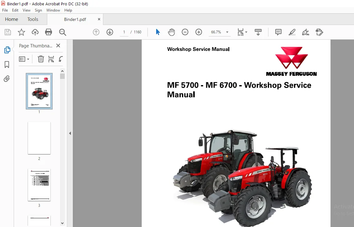
Massey Ferguson SA MF 5700 – MF 6700 Workshop Service Manual – PDF DOWNLOAD
Original price was: $49.95.$30.95Current price is: $30.95.
Massey Ferguson SA MF 5700 – MF 6700 Workshop Service Manual – PDF DOWNLOAD
Instant PDF Download
Available immediately
Save to Your Device
Download & keep forever
Antivirus Scanned
100% virus-free
Trusted Worldwide
175,000+ customers
Description
Massey Ferguson SA MF 5700 – MF 6700 Workshop Service Manual – PDF DOWNLOAD
TABLE OF CONTENTS:
Massey Ferguson SA MF 5700 – MF 6700 Workshop Service Manual – PDF DOWNLOAD
2 1 Separation of assemЫies 2-3
2 1 1 Removing/Refitting the ÑаЬ 2-3
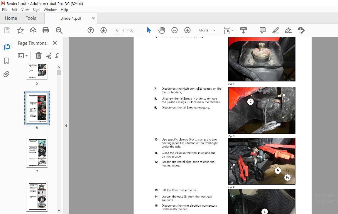
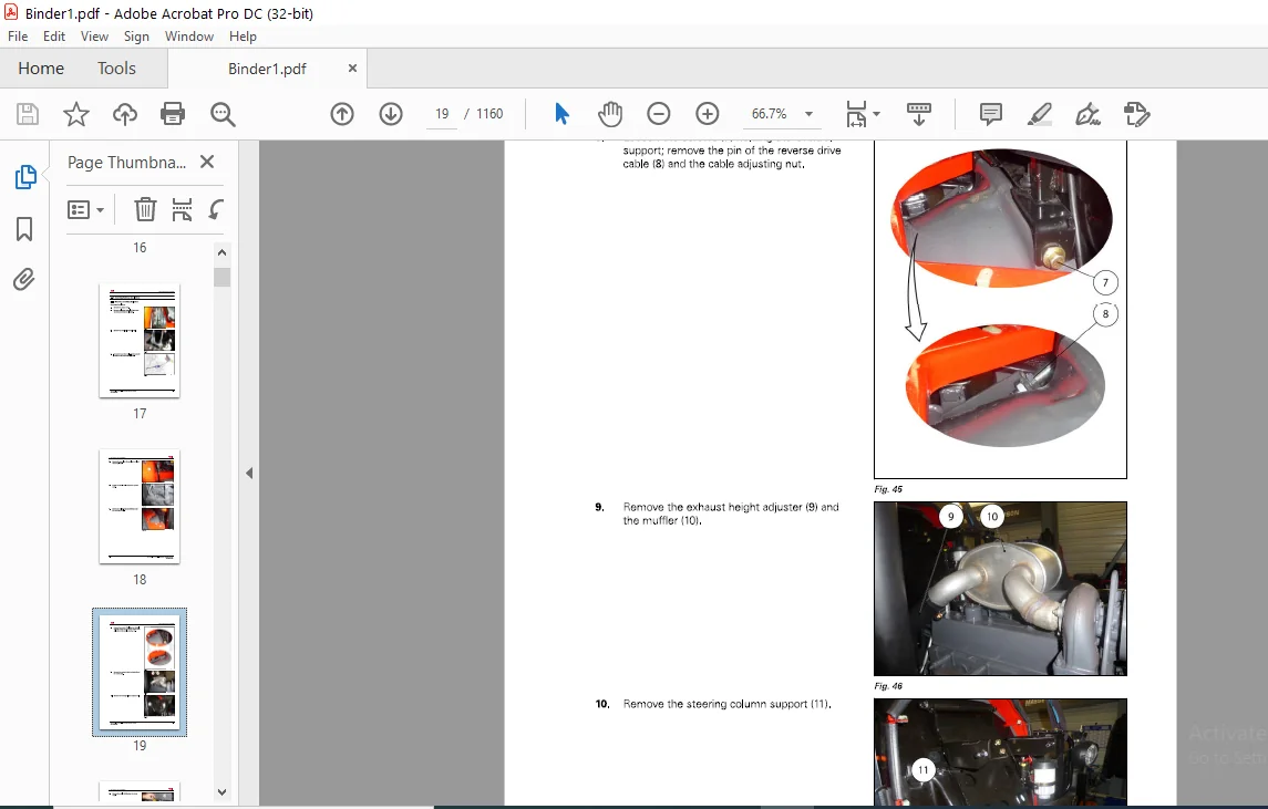
2 1 1 1 Removing the ÑаЬ 2-3
2 1 1 2 Refitting the ÑаЬ 2-7
2 1 2 Removing/Refitting the engine cover 2-1 2
2 1 2 1 Removing and refitting the engine cover 2-1 2
2 1 3 Removing/Refitting the front axle 2-1 3
2 1 3 1 Removing/Refitting the front axle 2-1 3
2 1 4 Removing/Refitting the platform 2-1 5
2 1 4 1 Removing and refitting the platform 2-1 5
2 1 5 Removing/Refitting the front support 2-19
2 1 5 1 Removing/Refitting the front support 2-19
2 1 6 Removing/Refitting the engine - gearbox assemЫy 2-2 2
2 1 6 1 Removing/Refitting the engine - gearbox assemЫy 2-2 2
2 1 7 Removing/Refitting the gеагЬох - геаr axle assemЫy 2-25
2 1 71 Removing/Refitting the gеагЬох - геаr axle assemЫy 2-25
3 1 Mechanical clutch 3-3
3 1 1 General 3-3
3 1 1 1 General 3-3
3 1 1 2 Operating principle of the mechanical clutch 3-3
3 1 2 Layout of components 3-7
3 1 2 1 Hydraulic clutch control 3-7
3 1 3 Adjustments, Ыeeding and calibration 3-9
3 1 3 1 Checking the sealing of the hydraulic clutch control 3-9
3 1 3 2 Checking the РТО shaft damper 3-1 1
3 1 4 DisassemЬly/reassemЫy 3-1 2
3 1 4 1 Removing the mechanical clutch 3-1 2
3 1 4 2 Refitting the mechanical clutch 3-1 3
3 1 4 3 Removing the hydraulic clutch control 3-1 4
Refitting the hydraulic clutch control 3-1 5
DisassemЫing the hydraulic clutch control 3-1 6
ReassemЫing the hydraulic clutch control 3-1 8
3 1 5 Service tools 3-2 3
3 1 5 1 Mechanical clutch 3-2 3
3 2 PowerShuttle torsional vibration damper 3-24
3 2 1 General 3-2 4
3 2 1 1 General 3-2 4
3 2 2 Layout of components 3-2 5
3 2 2 1 Layout of components 3-2 5
3 2 2 2 Tightening sequence for the screws 3-2 7
3 2 2 3 Tightening torques and application of threadlock compound 3-2 7
3 2 3 DisassemЬly/reassemЫy 3-28
3 2 3 1 Removing and refitting the torsional vibration damper 3-28
4 1 AGCO Power Tier 2/Tier 3 engine 4-3
4 1 1 lntroduction 4-3
4 1 1 1 Safety instructions 4-3
4 1 1 2 То the user 4-4
4 1 1 3 Engine construction 4-8
4 1 2 Specifications 4-1 5
4 1 2 1 Technical data 4-1 5
4 1 2 2 Tightening torques 4-2 2
Liquid quality requirements 4-2 3
Terminal diagram for CV54 ECU 4-2 6
Terminal diagram for С63 ECU 4-2 9
Cylinder ЫоÑk 4-3 1
Cylinder head 4-3 4
Valve mechanism 4-3 9
Crankshaft 4-4 3
Connecting rods and pistons 4-4 7
Counterbalance in 4 cylinder engines 4-51
Timing gear assemЫy 4-53
Lubrication system 4-56
Cooling system 4-59
4 1 3 1 0 Ðiг control system maintenance 4-61
4 2 AGCO Power Tier 4F engine 4-65
4 2 1 lntroduction 4-65
4 2 1 1 Safety instructions 4-65
4 2 1 2 То the user 4-66
4 2 1 3 Engine construction 4-70
4 2 2 Specifications 4-79
4 2 2 1 Technical data 4-79
4 2 2 2 T ightening torques 4-86
4 2 2 3 Special tools 4-87
Liquid quality requirements 4-90
Terminal diagram 4-93
4 2 3 Maintenance 4-96
Cylinder ЫоÑk 4-96
Cylinder head 4-99
Valve mechanism 4-104
Crankshaft 4-108
Connecting rods and pistons 4-112
Counterbalance in 4 cylinder engines 4-116
Timing gear assemЫy 4-118
Lubrication system 4-12 1
Cooling system 4-12 3
Air control system maintenance 4-12 6
Fuel system 4-12 9
SCR system 4-13 5
Engine control system 4-150
5 1 Mechanical reverse shuttle 5-5
5 1 1 Genernl ô€‚5
5 1 1 1 General 5-5
5 1 1 2 Operating principle of the synchronized mechanical reverse shuttle 5-6
5 1 1 3 Principle of operation of the single-cone synchronisers 5-8
5 1 2 Layout of components 5-10
5 1 2 1 Layout of components 5-10
5 1 3 Layout of components 5-1 3
5 1 3 1 Specific tightening torques, sealants and threadlock, adjustments of
bearings 5-1 3
5 1 4 Adjustments, Ыeeding and calibrations 5-1 5
5 1 4 1 Adjusting the mechanical reverse shuttle lever control 5-1 5
5 1 4 2 Checking the clearance at the input of the reverse shuttle shaft 5-1 5
5 1 4 3 Shimming the layshaft 5-17
5 1 4 4 Checking the shift forks 5-1 9
5 1 4 5 Checking the single-cone synchroniser 5-2 1
5 1 5 DisassemЬly/reassemЬly 5-2 3
5 1 5 1 Removing and refitting the mechanical reverse shuttle 5-2 3
5 1 5 2 Removing and refitting the primary shaft of the mechanical reverse
shuttle 5-2 8
5 1 6 Service tools 5-29
5 1 6 1 Mechanical reverse shuttle 5-29
5 2 PowerShuttle 5-зо
5 2 1 General 5-30
5 2 1 1 General 5-30
5 2 1 2 PowerShuttle operating principle 5-3 1
5 2 2 Layout of components 5-39
5 2 2 1 Layout of components - PowerShuttle 5-39
5 2 3 Layout of components 5-4 3
5 2 3 1 Specific tightening torques, sealants and threadlock, adjustments of
bearings 5-4 3
5 2 4 Adjustments, Ыeeding and calibrations 5-4 5
5 2 4 1 Shimming the reverse gеаг shaft 5-4 5
5 2 5 DisassemЬly/reassemЬly 5-4 6
5 2 5 1 Removing and refitting the PowerShuttle 5-4 6
5 2 5 2 Complete disassemЬly of the PowerShuttle 5-5 2
Complete reassemЫy of the PowerShuttle 5-62
DisassemЫy of the forward clutch system 5-71
ReassemЫy of the forward clutch system 5-76
DisassemЫy of the reverse clutch system 5-80
ReassemЫy of the reverse clutch system 5-86
5 2 6 Service tools 5-92
5 2 6 1 PowerShuttle 5-92
5 3 12 Ñ… 12 synchro gearbox with mechanical reverse shuttle 5-93
Operating principle of the 12Ñ…12 synchronized gearbox 5-94
Principle of operation of the douЫe-cone synchronisers 5-104
5 3 1 4 Principle of operation of the single-cone synchronisers 5-105
5 3 2 Layout of components 5-107
5 3 2 1 Location of components -Tightening torque, sealing product and
5 3 2 2
5 3 2 3
5 3 2 4
threadlock 5-107
Location of components - Positioning of forks 5-108
Layout of components -Synchronizer 5-109
12-ratio control module 5-110
5 3 3 Layout of components 5-113
Location of components -Gearbox 5-113
Location of components -tightening torque, sealing product and
threadlock 5-116
5 3 4 Adjustments, Ыeeding and calibrations 5-117
Adjusting the High/Low lever control (ÑаЬ version) 5-117
Adjustment of the screw оп the ratio selection module 5-117
Shimming the tapered roller bearings of the douЫe gear wheel of the
primary shaft 5-118
Shimming the primary and secondary shafts 5-12 0
Checking the shift forks 5-12 5
Checking the single-cone synchroniser 5-12 6
5 3 4 7 Checking the douЫe-cone synchroniser 5-129
5 3 5 DisassemЬly/reassemЫy 5-13 1
5 3 6
5 3 5 1 Removing and refitting the РТО shaft 5-13 1
5 3 5 2 Removing and refitting the ratio selection module 5-13 3
DisassemЫing the ratio selection module 5-13 5
ReassemЫing the ratio selection module 5-13 8
Removing and refitting the primary and secondary shafts 5-13 9
DisassemЫing and reassemЫing the primary shaft 5-14 4
DisassemЫing/reassemЫing the secondary shaft 5-15 5
DisassemЫing/reassemЫing the hare/tortoise assemЫy 5-160
Service tools 5-168
MF 5700 - MF 6700 - Workshop Service Мапиа/
ÐСТОО1919Ð
5 3 6 1
ТаЬ!е of contents
Service tools 5-168
5 4 1 2Ñ…1 2 Synchro gearbox with PowerShuttle 5-169
5 4 1 General 5-169
5 4 1 1
5 4 1 2
5 4 1 3
General information оп the 12 х 12 gearbox with PowerShuttle 5-169
Operating principle of the 12Ñ…12 synchronized gearbox 5-170
Principle of operation of the douЫe-cone synchronisers 5-180
5 4 1 4 Principle of operation of the single-cone synchronisers 5-181
5 4 2 Layout of components 5-183
Location of components -Tightening torque, sealing product and
threadlock 5-183
Location of components - Positioning of forks 5-184
Layout of components -Synchronizer 5-185
12-ratio control module 5-186
5 4 3 Layout of components 5-189
Location of components - Gearbox 5-189
Location of components -tightening torque, sealing product and
threadlock 5-192
5 4 4 Adjustments, Ыeeding and calibrations 5-193
Adjusting the High/Low lever control (ÑаЬ version) 5-193
Adjustment of the screw оп the ratio selection module 5-193
Shimming the tapered roller bearings of the douЫe gear wheel of the
primary shaft 5-194
Shimming the primary and secondary shafts 5-196
Checking the shift forks 5-2 01
Checking the single-cone synchroniser 5-2 02
Checking the douЫe-cone synchroniser 5-2 05
5 4 5 DisassemЬly/reassemЫy 5-2 07
Removing and refitting the ratio selection module 5-2 07
DisassemЫing the ratio selection module 5-2 10
ReassemЫing the ratio selection module 5-2 12
Removing and refitting the primary and secondary shafts 5-2 13
DisassemЫing and reassemЫing the primary shaft 5-2 2 0
DisassemЫing/reassemЫing the secondary shaft 5-2 3 0
DisassemЫing/reassemЫing the hare/tortoise assemЫy 5-2 3 5
Removing and refitting the РТО shaft - PowerShuttle 5-2 4 3
5 4 6 Service tools 5-2 4 4
5 4 6 1 Service tools 5-2 4 4
5 5 Super creeper speed 5-245
5 5 1 General 5-2 4 5
5 5 1 1 Genernl ô€£2 4 5
5 5 2 Principles of operation 5-2 4 5
MF 5700 - MF 6700 - Workshop Service Мапиа/
Operating principle diagrams 5-2 4 5
Principles of operation 5-2 4 8
5 5 3 Layout of components 5-2 4 9
5 5 3 1 Layout of components 5-2 4 9
5 5 4 Adjustments, Ыeeding and calibrations 5-2 5 2
5 5 4 1 Shimming the tapered bearings 5-2 5 2
5 5 5 DisassemЫy and reassemЫy 5-2 5 4
Preliminary steps 5-2 5 4
DisassemЫy 5-2 5 4
ReassemЫy 5-2 5 8
Final steps 5-2 62
6 1 General 6-5
6 1 1 General 6-5
6 1 1 1 General 6-5
6 1 1 2 Principles of operation 6-7
6 1 1 3 Schematic diagrams 6-9
6 2 GPA50/GPA52 trumpet housings 6-10
6 2 1 General 6-10
6 2 1 1 General 6-10
6 2 2 Principles of operation 6-1 1
6 2 2 1 Principles of operation 6-1 1
6 2 3 Layout of components 6-1 2
6 2 3 1 Layout of components 6-1 2
6 2 4 Adjustments, Ыeeding and calibrations 6-1 3
6 2 4 1 Shimming the planet gears 6-1 3
6 2 4 2 Shimming the tapered roller bearings of the axle shaft 6-1 6
6 2 5 DisassemЬly/reassemЫy 6-2 2
6 2 5 1 Specifications 6-2 2
6 2 5 2 Removing and refitting the trumpet housing assemЫy 6-2 4
6 2 5 3 Removing/refitting and disassemЫing/reassemЫing the planet carrier 6-27
6 2 5 4 Replacing tapered roller bearings and seals 6-3 2
6 2 5 5 Replacing а stud оп the flanged axle shaft 6-3 5
6 2 6 Service tools 6-3 5
6 2 6 1 General 6-3 5
6 2 6 2 GPA50/Final drives - Service tools 6-3 6
6 3 GPA50/GPA54 trumpet housings 6-37
6 3 1 General 6-37
6 3 1 1 General 6-37
6 3 2 Principles of operation 6-39
6 3 2 1 Principles of operation 6-39
6 3 3 Layout of components 6-40
6 3 3 1 Layout of components 6-40
6 3 4 DisassemЬly/reassemЫy 6-4 1
6 3 4 1 Specifications 6-4 1
6 3 4 2
6 3 4 3
Removing the trumpet housing assemЫy 6-4 3
Removing the final drive ring gear 6-47
Removing/refitting and disassemЫing/reassemЫing the planet carrier 6-4 8
DisassemЫy 6-5 4
Replacing а stud оп the flanged axle shaft 6-5 6
6 3 5 Service tools 6-5 6
6 3 5 1 General 6-5 6
6 3 5 2 GPA50/Final drives - Service tools 6-5 7
6 3 6 Adjustments, Ыeeding and calibrations 6-5 7
6 3 6 1 Shimming the planet gears 6-5 7
6 3 6 2 Shimming the tapered roller bearings of the axle shaft 6-6 0
6 4 GPA50/Crown wheel and pinion 6-66
6 4 1 General 6-6 6
6 4 1 1 General 6-6 6
6 4 1 2 Principles of operation 6-6 8
6 4 1 3 Electronic part 6-71
6 4 1 4 Logic of engagement of the differential 6-72
6 4 1 5 Mechanical part of the differential 6-74
6 4 1 6 Hydraulic part of the differential 6-74
6 4 2 Layout of components 6-76
6 4 2 1 Pinion and rear differential mechanism - Cross-section view 6-76
6 4 3 Adjustments, Ыeeding and calibration 6-79
6 4 3 1 Adjusting the pinion taper distance in the center housing 6-79
6 4 3 2 Adjusting the preload of the tapered bearings of the pinion 6-8 1
6 4 3 3 Adjusting and checking the backlash between the crown wheel and the
pInÑŽn 6-8 4
6 4 3 4 Procedure for shimming the preload of the tapered bearings of the
differential 6-8 7
6 4 3 5 Crown wheel and pinion/Procedure for shimming the preload of the
tapered bearings of the differential Ьу dimension 6-90
6 4 4 DisassemЬly/reassemЫy 6-90
6 4 4 1 Specifications 6-90
Removing and refitting the right-hand support and the mobile dog clutch
for the геаг differential unit/crown wheel assemЫy 6-92
Removing and refitting the геаг differential unit/crown wheel assemЫy 6-97
Removing and refitting the crown wheel 6-100
Removing and refitting the planet gears and sun gears 6-103
Removing and refitting the pinion 6-107
6 4 5 Service tools 6-113
6 4 5 1 Service tools 6-113
6 5 GPA50/Hydraulic tractor braking 6-116
6-2
6 5 1 General 6-116
6 5 1 1 General 6-116
6 5 1 2 Principles of operation 6-118
MF 5700 - MF 6700 - Workshop Service Мапиа/
ÐСТОО1919Ð
6 5 2
6 5 3
ТаЬ!е of contents
Electrical and hydraulics diagrams 6-12 1
6 5 2 1 Electrical diagrams 6-12 1
Layout of components 6-12 2
6 5 3 1 View of main brake system assemЫy 6-12 2
6 5 3 2 View of hand brake system assemЫy 6-12 3
6 5 3 3 Exploded view of brake system (hydraulic control) 6-12 3
6 5 3 4 View of the master cylinders 6-12 5
6 5 4 Adjustments, Ыeeding and calibration 6-12 5
6 5 4 1 Adjusting the main brakes 6-12 5
6 5 4 2 Adjusting the brake sensors оп the master cylinders 6-12 7
6 5 4 3 Bleeding the main brake system 6-12 7
6 5 4 4 Adjusting the hand brake 6-12 9
6 5 5 DisassemЬly/reassemЫy 6-12 9
6 5 5 1 Removing/refitting а hydraulic unit 6-12 9
6 5 5 2 Removing and refitting the disks and intermediate plates of а brake
mechanism 6-13 4
6 5 6 Service tools 6-13 8
6 5 6 1 Hydraulic tractor braking 6-13 8
6 6 GPA50/Hydraulic trailer braking 6-139
6 6 1 General 6-13 9
6 6 1 1 General 6-13 9
6 6 1 2 Principles of operation 6-140
6 6 2 Electrical and hydraulics diagrams 6-14 3
6 6 2 1 Electrical diagrams 6-14 3
6 6 3 Layout of components 6-14 4
6 6 3 1 View of the assemЫy 6-14 4
6 6 3 2 Blown-up view 6-14 6
6 6 4 Tests and diagnostics 6-14 7
6 6 4 1 Checking the trailer brake valve 6-14 7
6 6 5 Adjustments, Ыeeding and calibration 6-150
6 6 5 1 Bleeding the trailer brake circuit 6-150
6 6 6 DisassemЬly/reassemЫy 6-15 1
6 6 6 1 Removing and refitting the brake valve 6-15 1
6 6 6 2 DisassemЫing/reassemЫing the brake valve 6-15 2
6 7 GPA50/Linkage and hitch 6-15 5
6 7 1 General 6-15 5
6 7 1 1 General 6-15 5
6 7 1 2 Principles of operation 6-15 6
6 7 1 3 Overall operation 6-15 8
6 7 2 Layout of components 6-16 7
6 7 2 1 View of the assemЫy 6-16 7
MF 5700 - MF 6700 - Workshop Service Мапиа/
ÐСТОО1919Ð
6-3
ТаЬ!е of contents
6 7 2 2
6 7 2 3
6 7 2 4
6 7 2 5
6 7 2 6
6 7 2 7
Blown-up view 6-16 7
View of GPA 50 lift arm assemЫy 6-16 8
View of draft sensor assemЫy (top link) 6-16 9
View of draft sensor assemЫy (lift arm) 6-171
Overview of the linkage valve ( 5 7 I/min) 6-176
Overview of the linkage valve ( 98 I/min) 6-178
6 7 3 Adjustments, Ыeeding and calibrations 6-18 0
6 7 3 1 Procedure to adjust the linkage position sensor 6-180
6 7 3 2 Calibrating the linkage controls -version with ÑаЬ 6-18 0
6 7 4 DisassemЬly/reassemЫy 6-18 2
6 7 4 1 Removing and refitting the single arm (with draft sensor оп the top link)
6 7 4 2
6 7 4 3
6-18 2
Removing and refitting the single arm (with draft sensor оп the lift arms)
6-189
Removing/refitting the linkage valve 6-19 4
6 7 5 Service tools 6-196
6 7 5 1 Linkage and hitch 6-196
6 8 GPA50/Wheels and hubs 6-197
6-4
6 8 1 General 6-197
6 8 1 1 General 6-197
6 8 2 Layout of components 6-197
6 8 3
6 8 4
6 8 2 1 Layout of components 6-197
Adjustments, Ыeeding and calibration 6-198
6 8 3 1 Tightening torque 6-198
6 8 3 2 Track width adjustment 6-202
DisassemЬly/reassemЫy 6-203
6 8 4 1 DisassemЬly/reassemЫy 6-203
7 1 General 7-3
7 1 1 Overall operation 7-3
7 1 1 1 РТО operating principle 7-3
7 1 2 Electrical part 7-3
7 1 2 1 Electronic part 7-3
7 1 2 2 Management of the РТО clutch solenoid valve 7-4
7 1 2 3 Safety part 7-6
7 1 3 Mechanical part 7-8
7 1 3 1 Mechanical part 7-8
7 1 4 Hydraulic part 7-8
7 1 4 1 Hydraulic part 7-8
7 2 Clutch 7-11
7 2 1 General 7-1 1
7 2 1 1 General 7-1 1
7 2 1 2
7 2 1 3
Principles of operation 7-1 1
Gerotor module 7-1 3
7 2 2 Layout of components 7-1 4
7 2 2 1 View of the assemЫy 7-1 4
7 2 3 DisassemЬly/reassemЫy 7-1 5
7 2 3 1 DisassemЫing/reassemЫing the РТО clutch 7-1 5
7 2 3 2 DisassemЫing/reassemЫing the Gerotor module 7-19
7 3 One-speed gearbox 7-23
7 3 1 Genernl ô€ƒ2 3
7 3 1 1 General 7-2 3
7 3 1 2 Principles of operation 7-2 3
7 3 2 Layout of components 7-25
7 3 2 1 View of the assemЫy 7-25
7 3 3 Adjustments, Ыeeding and calibration 7-26
7 3 3 1 Shimming the tapered roller bearings of the primary shaft 7-26
7 3 3 2 Shimming the tapered roller bearings of the secondary shaft 7-27
7 3 4 DisassemЬly/reassemЫy 7-2 8
7 3 4 1 DisassemЫing the РТО unit 7-2 8
7 3 4 2 Refitting the РТО unit 7-3 1
7 3 5 Service tools 7-3 4
7 3 5 1 One-speed gearbox 7-3 4
MF 5700 - MF 6700 - Workshop Service Мапиа/
ÐСТОО1919Ð
7-1
ТаЬ!е of contents
7 4 2-speed gearbox 7-35
7 4 1 General 7-35
7 4 1 1 General 7-35
7 4 2 Layout of components 7-38
7 4 2 1 View of the assemЬly 7-38
7 4 2 2
7 4 2 3
7 4 2 4
Blown-up view 7-4 1
ldentification of ports 7-4 4
Kinematics 7-4 5
7 4 3 Adjustments, Ыeeding and calibrations 7-4 7
7 4 3 1 Shimming shafts of the rear РТО with two electrohydraulic speeds 7-4 7
7 4 4 DisassemЬly/reassemЫy 7-5 2
7 4 4 1 Specifications 7-5 2
7 4 4 2 Removing/refitting and disassemЫing/reassemЫing the rear РТО with
two electrohydraulic speeds 7-5 3
7 4 5 Service tools 7-76
7 4 5 1 Geneml ô€‘76
7 4 5 2 GPA50/Rear РТО with two electrohydraulic speeds -Service tools 7-76
7 5 3-speed gearbox 7-79
7-2
7 5 1 Geneml ô€‘7 9
7 5 1 1 General 7-7 9
7 5 1 2 Principles of operation 7-80
7 5 2 Layout of components 7-82
7 5 2 1 Layout of components 7-82
7 5 2 2 View of the assemЬly 7-83
7 5 2 3 Blown-up view 7-85
7 5 2 4
7 5 2 5
ldentification of ports 7-86
Kinematics 7-88
7 5 3 Adjustments, Ыeeding and calibrations 7-91
7 5 3 1 Preparation for shaft shimming 7-91
7 5 4 DisassemЬly/reassemЬly 7-95
7 5 4 1 Specifications 7-95
7 5 4 2 Preliminary steps 7-96
7 5 5 Service tools 7-1 16
7 5 5 1
7 5 5 2
General 7-1 16
GPA50/Rear РТО with three electrohydraulic speeds - Service tools 7-1 16
8 1 Four-wheel drive clutch 8-3
8 1 1 General 8-3
8 1 1 1 General 8-3
8 1 1 2 Principles of operation 8-5
8 1 2 Layout of components 8-9
8 1 2 1 Layout of the 4-wheel drive clutch components 8-9
8 1 2 2 Exploded view of the four-wheel drive clutch mechanism 8-10
8 1 3 Adjustments, Ыeeding and calibrations 8-1 1
8 1 3 1 Shimming the four-wheel drive clutch 8-1 1
8 1 4 DisassemЬly/reassemЫy 8-1 2
8 1 4 1 Removing the four-wheel drive clutch assemЫy 8-1 2
8 1 4 2 DisassemЫy of the four-wheel drive clutch 8-1 4
8 1 4 3 ReassemЫy of the four-wheel drive clutch 8-1 6
8 1 4 4
8 1 4 5
8 1 4 6
Refitting the four-wheel drive clutch assemЫy 8-20
Extracting and fitting the ball bearing 8-2 2
Extracting and fitting the hydraulic ring 8-2 3
9 1 Open Center 57 I/min 9-7
9 1 1 General 9-7
9 1 1 1 Description of the hydraulic system 9-7
9 1 1 2 Specifications 9-9
9 1 2 Layout of components 9-9
9 1 2 1 Layout of components 9-9
9 1 3 Topic title-diag ref/Hydraulic diagrams 9-1 1
9 1 3 1 Hydraulic diagram 57 I/min with mechanical shuttle 9-1 1
9 1 3 2 Hydraulic diagram 57 I/min with PowerShuttle 9-1 2
9 2 57 I/min Open Center/Right-hand cover plate 9-15
9 2 1 General 9-15
9 2 1 1 Genernl 􀀿15
9 2 2 Layout of components 9-15
9 2 2 1 View of the right-hand hydraulic cover plate 9-15
9 2 2 2
9 2 2 3
Location of components -lnside view 9-16
Right-hand Cover -T ightening torque and application of Loctite 9-1 7
9 2 3 DisassemЬly/reassemЫy 9-18
9 2 3 1 Removing and refitting the right-hand hydraulic cover plate 9-18
9 3 57 I/min Open Center/Left-hand cover plate 9-20
9 3 1 General 9-20
9 3 1 1 General 9-20
9 3 2 Layout of components 9-20
9 3 2 1 Layout of components 9-20
9 3 3 DisassemЬly/reassemЬly 9-2 1
9 3 3 1 Removing/refitting the left-hand cover plate 9-2 1
9 4 57 I/min Open Center/Hydraulic pump 9-23
9 4 1 General 9-2 3
9 4 1 1 General 9-2 3
9 4 1 2 Principles of operation 9-2 3
9 4 2 Layout of components 9-2 4
9 4 2 1 View of the assemЬly 9-2 4
9 4 3 Tests and diagnostics 9-25
9 4 3 1 General 9-25
9 4 3 2 Equipment pump flow check (57 I/min Open Center system) 9-25
9 4 3 3 Checking the steering pump flow rate 9-2 7
MF 5700 - MF 6700 - Workshop Service Мапиа/
ÐСТОО1919Ð
9-1
ТаЬ!е of contents
9 4 4 DisassemЬly/reassemЫy 9- 2 8
9 4 4 1 Removing and refitting the hydraulic pumps (right-hand cover plate) 9- 2 8
9 5 57 I/min Open Center/Pressure-limiting valve 9-31
9 5 1 General 9- 3 1
9 5 1 1 General 9- 3 1
9 5 1 2 Principles of operation 9- 3 1
9 5 2 Layout of components 9- 3 2
9 5 2 1 View of the assemЫy 9- 3 2
9 5 3 Tests and diagnostics 9- 3 3
9 5 3 1 General 9- 3 3
9 5 3 2 Checking the maximum pressure of the high-pressure system 9- 3 3
9 5 4 DisassemЬly/reassemЫy 9- 3 4
9 5 4 1 DisassemЫing/reassemЫing the pressure relief valve 9- 3 4
9 6 57 I/min Open Center/21-bar valve 9-36
9 6 1 General 9- 3 6
9 6 1 1 General 9- 3 6
9 6 1 2 Principles of operation 9- 3 6
9 6 2 Layout of components 9- 3 7
9 6 2 1 View of the assemЫy 9- 3 7
9 6 2 2 Layout of the 2 1-bar solenoid valve components 9- 3 7
9 6 3 Tests and diagnostics 9- 3 8
9 6 3 1 Checking the adjustment of the 2 1-Ьаг valve 9- 3 8
9 6 3 2 Checking the clutches and slave devices for leaks 9- 3 8
9 6 3 3 Check for clutch and slave device load losses 9-40
9 6 4 DisassemЬly/reassemЫy 9-4 1
9 6 4 1 Removing and refitting the 2 1 Ьаг valve 9-4 1
9 6 4 2 Removing and refitting the 2 1-Ьаг solenoid valve bracket 9-4 2
9 7 57 I/min Open Center/Spool valve 9-44
9-2
9 7 1 Genernl 9-44
9 7 1 1 General 9-44
9 7 1 2 AvailaЫe spool valves 9-44
9 7 1 3 Flow divider 9-46
9 7 1 4 Principles of operation 9-46
9 7 2 Layout of components 9-47
9 7 2 1 View of the assemЫy 9-47
9 7 3 Tests and diagnostics 9-47
9 74
9 7 3 1 General 9-47
9 7 3 2 Checking the flow divider 9-4 8
9 7 3 3 Checking the Kick-out pressure 9-4 9
DisassemЬly/reassemЫy 9-4 9
MF 5700 - MF 6700 - Workshop Service Мапиа/
ÐСТОО1919Ð
ТаЬ!е of contents
9 7 4 1 Removing and refitting the auxiliary spool valves 9-4 9
9 8 Open Center 98 1/min 9-52
9 8 1 General 9-5 2
9 8 1 1 Description of the hydraulic system 9-5 2
9 8 1 2 Specifications 9-54
9 8 2 Layout of components 9-55
9 8 2 1 Layout of components 9-55
9 8 3 Topic title-diag ref/Hydraulic diagrams 9-5 9
9 8 3 1 Hydraulics diagram 9 8 I/min w ith mechanical reverse shuttle 9-5 9
9 8 3 2 Hydraulics diagram 9 8 I/min w ith mechanical reverse shuttle 9-60
9 9 98 1/min Open Center/Right-hand cover plate 9-63
9 9 1 General 9-6 3
9 9 1 1 General 9-6 3
9 9 2 Layout of components 9-6 3
9 9 2 1 Layout of components 9-6 3
9 9 2 2 Layout of components 9-64
9 9 2 3 Right-hand Cover - T ightening torque and application of Loctite 9-65
9 9 3 DisassemЬly/reassemЫy 9-66
9 9 3 1 Removing and refitting the right-hand hydraulic cover plate 9-66
9 10 98 1/min Open Center/Left-hand cover plate 9-68
9 1 0 1 General 9-6 8
9 1 0 1 1 General 9-6 8
9 1 0 2 Layout of components 9-6 8
9 1 0 2 1 Layout of components 9-6 8
9 1 0 2 2 Layout of components - T ightening torque and application of Loctite 9-6 9
9 1 0 3 DisassemЬly/reassemЫy 9-7 0
9 1 0 3 1 Removing and refitting the left-hand cover plate 9-7 0
9 11 98 1/min Open Center/Hydraulic pump 9-72
9 1 1 1 General 9-7 2
9 1 1 1 1 General 9-7 2
9 1 1 1 2 Principles of operation 9-7 2
9 1 1 2 Layout of components 9-7 3
9 1 1 2 1 Layout of hydraulic pump components (left-hand cover plate) 9-7 3
9 1 1 2 2 Layout of components - right-hand hydraulic pump 9-7 4
9 1 1 3 Test and diagnostic 9-7 5
9 1 1 3 1 General 9-7 5
9 1 1 3 2
9 1 1 3 3
Equipment pump flow check ( 9 8 I/min Open Center system) 9-7 5
Checking the steering pump flow rate 9-7 8
9 1 1 4 DisassemЬly/reassemЫy 9-7 9
9 1 1 4 1 Removing and refitting the hydraulic pumps (right-hand cover plate) 9-7 9
MF 5700 - MF 6700 - Workshop Service Мапиа/
ÐСТОО1919Ð
9-3
ТаЬ!е of contents
9 11 4 2 Removing and refitting the hydraulic pump (left-hand cover plate) 9-81
9 12 98 I/min Open Center/Pressure-limiting valve 9-83
9 1 2 1 General 9-83
9 1 2 1 1 General 9-83
9 1 2 1 2 Principles of operation 9-83
9 12 2 Layout of components 9-84
9 1 2 2 1 View of the assemЫy 9-84
9 1 2 3 Test and diagnostics 9-85
9 1 2 3 1 General 9-85
9 1 2 3 2 Equipment pump flow check ( 9 8 I/ min Open Center system) 9-85
9 1 2 4 DisassemЬly/reassemЫy 9-88
9 1 2 4 1 DisassemЫing/reassemЫing the pressure relief valve 9-88
9 1 2 4 2 Removing and refitting the pressure-limiting valve (left-hand cover plate)
9-89
9 13 98 I/min Open Center/21-bar valve 9-90
9 13 1 General 9-9 0
9 13 1 1 General 9-9 0
9 13 1 2 Principles of operation 9-9 0
9 1 3 2 Layout of components 9-9 1
9 1 3 2 1 View of the assemЫy 9-9 1
9 13 2 2 Layout of components of 2 1-bar solenoid valves 9-9 2
9 13 3 Tests and diagnostics 9-9 2
9 1 3 3 1 Checking the adjustment of the 2 1-bar valve 9-9 2
9 13 3 2 Checking the clutches and slave devices for leaks 9-9 2
9 13 3 3 Check for clutch and slave device load losses 9-9 4
9 13 4 DisassemЬly/reassemЫy 9-95
9 13 4 1 Removing and refitting the 2 1 bar valve 9-95
9 13 4 2 Removing and refitting the 2 1-bar solenoid valve bracket 9-96
9 14 98 I/min Open Center/Pump coupling valve 9-98
9 14 1 General 9-9 8
9 1 4 1 1 General 9-9 8
9 14 1 2 Principles of operation 9-9 8
9 1 4 2 Layout of components 9-100
9 1 4 2 1 Layout of components 9-100
9 14 3 DisassemЬly/reassemЫy 9-100
9 14 3 1 Removing and refitting the pump coupling valve 9-100
9 15 98I/min Open Center/Spool valve 9-102
9-4
9 15 1 General 9-10 2
9 15 1 1
9 15 1 2
General 9-10 2
AvailaЫe spool valves 9-10 2
MF 5700 - MF 6700 - Workshop Service Мапиа/
ÐСТОО1919Ð
9 15 1 3
9 15 1 4
ТаЬ!е of contents
Flow divider 9-10 4
Principles of operation 9-10 4
9 15 2 Layout of components 9-105
9 15 2 1 View of the assemЫy 9-105
9 15 3 Tests and diagnostics 9-105
9 15 3 1 General 9-105
9 15 3 2 Checking the flow divider 9-106
9 15 3 3 Checking the Kick-out pressure 9-107
9 15 4 DisassemЬly/reassemЫy 9-107
9 15 4 1 Removing and refitting the auxiliary spool valves 9- 107
10 1 Electrical system 10-3
10 1 1 General 10-3
10 1 2 Electrical display: location of the connectors 10-5
10 2 Alternator 10-21
10 2 1 Tests and diagnostics 10-2 1
10 2 1 1 Alternator connections 10-2 1
10 2 1 2 Preliminary checks 10-2 1
10 2 1 3
10 2 1 4
10 2 1 5
10 2 1 6
10 2 1 7
10 2 1 8
Check the alternator wiring 10-2 1
Check the load current and regulated voltage 10-2 2
Check the maximum output of the alternator 10-2 2
Looking for а voltage drop in the insulated circuit 10-2 2
Looking for а voltage drop in the earth circuit 10-2 2
General 10-2 3
10 2 1 9 Checking the brushes, springs and slip rings 10-2 4
10 2 2 DisassemЬly/reassemЫy 10-2 4
10 2 2 1 Removing the alternator 10-2 4
10 2 2 2 Refitting the alternator 10-30
10 3 Starter 10-32
10 3 1 General 10-3 2
10 3 1 1 Principles of operation 10-3 2
10 3 2 Tests and diagnostics 10-3 3
10 3 2 1 Test procedure 10-3 3
10 3 3 DisassemЬly/reassemЫy 10-3 4
10 3 3 1 Removing/refitting of the starter 10-3 4
10 4 Battery 10-36
10 4 1 General 10-36
10 4 1 1 Description and use 10-36
10 4 1 2 Maintenance 10-36
10 4 2 Tests and diagnostics 10-37
10 4 2 1 Test procedure 10-37
10 4 3 DisassemЬly/reassemЫy 10-38
10 4 3 1 Removing/refitting the battery 10-38
11 1 Error codes 11-7
11 1 1 Еггог codes: general 11- 7
11 1 1 1 Description of еггог code format 11- 7
11 1 2 Еггог codes: ins trument panel 11-8
11 1 2 1 Еггог code О Х 70 11-8
11 1 2 2 Еггог code О Х 71 11-8
11 1 2 3 Еггог code О Х 7 2 11-9
11 1 2 4
11 1 2 5
11 1 2 6
Еггог code О Х 7 3 11-9
Еггог code О Х 74 11-9
Еггог code О Х 75 11-9
Errorcode4 X 09 11-10
Errorcode4 X 10 11-10
Еггог code 4 Х 11 11-11
Еггог code 4 Х 1 3 11-11
Еггог code 4 Х 14 11-11
Еггог code 4 Х 15 11-11
Еггог code 4 Х 1 6 11-11
Еггог code 4 Х 1 7 11-1 2
Errorcode4 X 40 11-1 2
Errorcode4 X 55 11-1 2
Еггог code 4 Х 85 11-1 2
Errorcode4 X 90 11-1 3
Еггог code 4 Х 91 11-1 3
Errorcode4 X 9 2 11-1 3
Еггог code 4 Х О Р11-1 3
Еггог code 4 Х ОВ 11-14
Errorcode4 X 0C 11-14
MF 5700 - MF 6700 - Workshop Service Мапиа/
Error code 4 X C0 11-1 5
Error code 4 X C1 11-1 5
Error code 4 X C 2 11-1 6
Error code 4 X C3 11-1 6
Error code 4 X ED 11-1 6
Error code 4 X FD 11-1 6
Error code 4 X FE 11-1 7
Error code 4 X FF 11-1 7
11 1 4 Front a xle and di ffe rential lock e rror codes 11-1 7
11 1 4 1
11 1 4 2
Error code 5 X 33 11-1 7
Error code 5 Х 5 3 11-1 7
11 1 5 Live РТО 11-1 8
Error code 6 Х 0 4 11-1 8
Error code 6 Х 0 6 11-1 8
Error code 6 Х 0 7 11-1 8
Error code 6 Х 0 8 11-1 8
Error code 6 Х 0 9 11-1 9
Error code 6 X 1 E 11-1 9
Error code 6 Х 4 Р11-1 9
Error code 6 X 4B 11-1 9
Error code 6 Х 4С 11-1 9
Error code 6 X 4 D 11-20
Error code 6 Х 4Е 11-20
Error code 6 Х Е 2 11-20
Error code 6 Х Е 7 11-20
11 1 6 Rea r linkage 11-21
Error code 8 X 1 2 11-21
Error code 8 X 1 6 11-21
Error code 8 X 1 8 11-21
Error code 8 Х 2 2 11-21
Error code 8 Х 2 3 11-2 2
Error code 8 Х 2 7 11-2 2
Error code 8 Х 2 8 11-2 2
Error code 8 Х 2 9 11-2 2
Error code 8 Х 3 2 11-2 2
Error code 8 Х 51 11-2 3
Error code 8 Х 60 11-2 3
Error code 8 Х 61 11-2 3
Error code 8 Х 70 11-2 3
Error code 8 Х 1 Р11-2 4
Error code 8 Х 1 В 11-2 4
11 2 Component files 11-26
Ð¥ 5 - 4-wheel drive s olenoid valve -des cription 11-2 6
Ð¥5 - 4-wheel drive s olenoid valve -tes t 11-2 6
Ð¥6 - D iffe rential lock s olenoid valve -des cription 11-2 7
Ð¥6 - D iffe rential lock s olenoid valve -tes t 11-2 8
Х7 - Rea r РТО s olenoid valve -des cription 11-29
Х7 - Rea r РТО s olenoid valve -tes t 11-29
Ð¥1 9 -Transmis sion hydraulic oil temperature sens or- description 11-30
Ð¥1 9 - Transmis s i on hydraulic oil tempe ratu re s ens or-tes t 11-31
Х 20 - Transmis sion filter Ыockage sens or- description 11-32
Х 20 - Transmis sion filter Ыockage sens or- tes t 11-33
Ð¥ 2 7 - Rea r linkage s olenoid valve -des cription 11-3 4
Ð¥ 2 7- Rear linkage s olenoid valve- tes t 11-35
Х 2 8- Solenoid valve forг еаг linkage lifting/lowering selection -description 11-37
Ð¥ 2 8 - Solenoid valve for rea r linkage lifting/lowe ring s election -tes t 11-38
Ð¥30 - Rear linkage pos ition sens or- description 11-40
Ð¥30 - Rear linkage pos ition sens or- tes t 11-41
11 2 1 7 Х 3 2 - Тор link draft s ens or-des cription 11- 4 2
11 2 1 8 Х32 -Тор link draft sens or- tes t 11-43
Ð¥ 5 5 - lns t rument panel -des cription 11- 4 4
Ð¥ 56 - PowerShuttle lever- description 11-46
Ð¥ 5 6 - Powe rShuttle lever-tes t 11- 48
11 2 2 2 Х 5 8 - Win ds creen wipe r an d di recti on in dicator cont rol unit -des cription 11-50
11 2 2 3 Х 6 6 - Left-han d b rake pedal s ens or-des cription 11-51
11 2 2 4 Х66 - Left-hand brake pedal sens or- tes t 11-5 2
11 2 2 5 Х67 - Right-han d b rake pedal s ens or-des cription 11-5 4
11 2 2 6 Х67 - Right-han d b rake pedal s ens or-tes t 11-5 5
11 2 2 7 Х68 - C lutch pedal s ens or- des cription 11- 5 6
11 2 2 8 Х68 - C lutch pedal s ens or-tes t 11-59
11 2 2 9 Х71 - Th rottle pedal s ens or-des cription 11-63
11 2 30 Х71 - Th rottle pedal s ens or-tes t 11-6 4
11 2 31 Х97 - Linkage lifting/lowering switch on left-hand fender- description 11-6 5
11 2 32 Х97 - Linkage lifting/lowering switch on left-hand fender- tes t 11-66
11 2 33 Х1 2 8 - Rea r РТО engagement s witch -des cription 11-67
11 2 3 4 Х1 36 - D iffe rential lock s witch -des cription 11-68
11 2 3 5 Х1 37 - 4-wheel drive s witch -des cription 11-69
MF 5700 - MF 6700 - Workshop Service Мапиа/
Ð¥1 38 - Haza rd wa rning lights indicator light and s witch -des cription 11-70
Ð¥1 5 2 - Sta rt s witch -des cription 11-71
Ð¥1 77 - Linkage cont rolle r-des cription 11-7 2
Ð¥1 8 3 - D iagnos tics connector (t ractor CAN/engine auxilia ry CAN) - des cription 11-7 4
Ð¥1 9 7 - D ies el fuel gage -des cription 11-75
Ð¥30 2 - Switch for p res elected engine s peed Ð-des cription 11-76
Ð¥363 - Rea r linkage lifting/lowe ring/quick s oil engagement s witch -des cription 11-77
Ð¥363 - Rea r linkage lifting/lowe ring/quick s oil engagement s witch -tes t 11-78
Ð¥ 4 70 - Ope rator p res ence in s eat s witch -des cription 11-79
Ð¥ 4 70 - Ope rator p res ence in s eat s witch - tes t 11-80
Ð¥ 481 - Engine speed sens or- description 11-81
Ð¥ 481 - Engine speed sens or- tes t 11-8 2
Ð¥ 48 2 - Theoretical forward speed sens or- description 11-83
Ð¥ 48 2 - Theoretical forward speed sens or- tes t 11-83
Ð¥ 483- lntermediate speed sens or- description 11-8 5
Ð¥ 483- lntermediate speed sens or- tes t 11-8 5
Ð¥ 49 3 - Lub ricati on s witch -des cription 11-8 6
Ð¥ 49 3 - Lub ricati on s witch -tes t 11-8 7
Х 49 8 - РТО b rake s olenoid valve -des cription 11-88
Х 49 8 - РТО b rake s olenoid valve -tes t 11-89
Ð¥ 5 5 6 - Forwa rd s olenoid valve -des cription 11-90
Ð¥ 5 5 6 - Forwa rd s olenoid valve -tes t 11-91
Ð¥ 5 5 7 - Revers e s olenoid valve -des cription 11-91
Ð¥ 5 5 7 - Revers e s olenoid valve -tes t 11-9 2
Ð¥ 59 4 - AgC ommandâ„¢ unit - des cription 11-9 3
Ð¥61 8 - Parking brake sens or- description 11-93
Ð¥6 5 2 - Haza rd wa rning light unit -des cription 11-9 4
Ð¥740 - Rea r work lights s witch -des cription 11-9 6
Ð¥741 - Front work lights s witch -des cripti on 11-9 7
Ð¥7 4 2 - Rota ry beacon s witch -des cription 11-98
Ð¥743 - UP/D OWN navigation s witch -des cription 11-99
Ð¥74 4 - -/+ navigation s witch -des cription 11-99
Ð¥7 4 6 - Safety s ta rt s witch -des cription 11-1 0 0
Ð¥747- PowerShuttle respons e potentiometer- description 11-1 0 2
Ð¥747- PowerShuttle respons e potentiometer- tes t 11-1 0 3
Ð¥750 - Rear-linkage intermix potentiometer- description 11-1 0 3
Ð¥750 - Rear-linkage intermix potentiometer- tes t 11-1 0 5
Ð¥751 - Rear-linkage height/depth adjustment potentiomete r-des cription 11-1 0 6
Ð¥751 - Rear-linkage height/depth adjustment potentiomete r-tes t 11-1 0 8
Ð¥771 - Transmis s ion cont roller- description 11-11 0
Х776 - Rear РТО end-fitting speed sens or- description 11-11 2
MF 5700 - MF 6700 - Workshop Service Мапиа/
ÐСТОО1919Ð
ТаЬ!е of contents
11 2 77 Х776 - Rear РТО end-fitting s peed s ens or-tes t 11-11 3
11 2 7 8 Х897 - Rear-linkage rais ed pos ition adjustment potentiometer- description 11-11 4
11 2 79 Х89 7 - Rear-linkage rais ed pos ition adjustment potentiometer -tes t 11-11 5
11 2 80 Х898 - Rear-linkage lowering s peed adjustment potentiometer- description 11-11 6
11 2 81 Х898 - Rear-linkage lowering s peed adjustment potentiometer -tes t 11-11 7
11 2 8 2 Х90 6 - Ouick declutching s witch -des cription 11-11 8
11 2 8 3 Х90 6 - Ouick declutching s witch -tes t 11-11 9
11 2 8 4 Х9 3 4 - Rear-linkage active trans port control button 11-11 9
11 3 Setting parameters 11-121
11 3 1 Label code des cription 11-1 21
11 3 2 C onfiguring the label codes us ing EDT 11-1 2 2
11 3 3 C onfiguring the label codes us ing the ins trument panel 11-1 2 2
11 3 4 Setting the tа Ые of cons tants parameters 11-1 2 4
11 3 5 Setting the engine and maintenance hours parameters 11-1 2 5
11 3 6 C learing an Autotronic 7 11-1 2 5
11 3 7 Navigation s hared Ьу the different parameters 11-1 2 6
11 3 8 OЬtaining an authoris ation code 11-1 2 6
11 3 9 C reating an authoris ati on code as factory product s upport 11-1 2 7
11 4 Diagnostic files 11-130
D iagnos tic file: program - parameters 11-1 30
D iagnos tic file: program - parameters - calibrations 11-1 30
D iagnos tic file: component 11-1 30
D iagnos tic file: fus es - program - parameters - calibrations 11-1 30
D iagnos tic file: fus es - component - harnes s 11-1 30
D iagnos tic file: fus es - calibrations - component - controller power s upply- harnes s 11-1 31
D iagnos tic file: fus es - component - controller power s upply - harnes s 11-1 31
D iagnos tic file: fus es - program - parameters - CAN - component- harnes s 11-1 31
D iagnos tic file: fus es - CAN - harnes s - component 11-1 31
D iagnos tic file: Error code 8 Х 50 and 8 Х 51 11-1 3 2
D iagnos tic file: Error code О Х 41 11-1 3 2
D iagnos tic file: Error code О Х 4 2 11-1 3 2
11 4 1 3 D iagnos tic file: Error code О Х 4 5 11-1 3 2
11 5 Generic procedures 11-133
11 5 1 Lis t of generic procedures 11-1 33
11 5 2 Checking the insulation of а harnes s 11-1 33
11 5 3 Checking the continuity of а harnes s 11-1 33
11 5 4 Checking the CAN network 11-1 3 4
11 5 5 Checking а harnes s 11-1 36
11 5 6 Measuring a voltage 11-1 37
11 5 7 Measuring the res is tance of а component 11-1 37
MF 5700 - MF 6700 - Workshop Service Мапиа/
ÐСТОО1919Ð
11-5
ТаЬ!е of contents
11 5 8 Meas u ring cu rrent 11-1 38
11 5 9 Hook-on ammete r p rocedu re 11-1 38
11 5 1 0 Ammete r p rocedu re 11-1 38
12 Operator environment
12 1 Platform operator's seat 12-з
12 1 1 General 12-3
12 1 1 1 General 12-3
12 1 2 Layout of components 12-6
12 1 2 1 View of the ROPS 12-6
12 1 2 2 FOPS roof 12-7
12 1 3 DisassemЬly/reassemЫy 12-7
12 1 3 1 Removing and refitting the safety ÑаЬ 12-7
12 2 СаЬ operator's seat 12-9
12 2 1 General 12-9
12 2 1 1 General 12-9
12 2 2 Layout of components 12-10
12 2 2 1 T ightening torque and application of Loctite 12-10
12 2 3 Adjustments, Ыeeding and calibrations 12-11
12 2 3 1 Adjusting the foot throttle pedal 12-11
12 2 4 DisassemЬly/reassemЫy 12-11
12 2 4 1 Removing the cab 12-11
12 2 4 2 Refitting the ÑаЬ 12-16
12 З Seat 12-21
12 3 1 General 12-2 1
12 3 1 1 General 12-2 1
12 3 2 Layout of components 12-2 3
12 3 2 1 Exploded view 12-2 3
12 3 3 DisassemЬly/reassemЫy 12-2 4
12 3 3 1 Removing the seat 12-2 4
12 3 3 2 ReassemЫy 12-2 7
12 4 Standard air conditioning 12-28
12 4 1 General 12-28
General 12-28
Technical specifications 12-28
Principles of operation 12-3 1
Schematic diagram of the air conditioning 12-3 3
Layout of components 12-3 5
12 4 2 Tests and diagnostics 12-3 6
12 4 2 1 General 12-3 6
12 4 2 2 Air conditioning system faults 12-37
12 4 2 3 Sealing test оп the air conditioning system 12-40
12 4 3 Adjustments, Ыeeding and calibrations 12-4 2
12 4 3 1 Safety instructions 12-4 2
General maintenance 12-4 3
Adjusting the clutch air gap 12-4 4
Draining the air conditioning system 12-4 4
Drafting the system 12-4 5
Filling the system with oil and adding а tracer 12-46
Filling the system with refrigerant 12-46
Checking the sealing 12-47
MASSEY FERGUSON SA MF 5700 – MF 6700 WORKSHOP SERVICE MANUAL – PDF DOWNLOAD:
IMAGES PREVIEW OF THE MANUAL:
PLEASE NOTE:
- This is the SAME exact manual used by your dealers to fix your vehicle.
- The same can be yours in the next 2-3 mins as you will be directed to the download page immediately after paying for the manual.
- Any queries / doubts regarding your purchase, please feel free to contact [email protected]
S.V