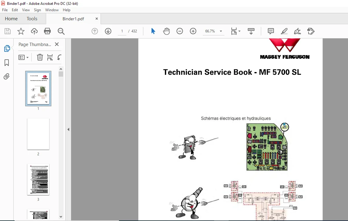
Massey Ferguson SA MF 5700 SL Technician Workshop Service Manual – PDF DOWNLOAD
Original price was: $86.95.$29.95Current price is: $29.95.
Massey Ferguson SA MF 5700 SL Technician Workshop Service Manual – PDF DOWNLOAD
Description
Massey Ferguson SA MF 5700 SL Technician Workshop Service Manual – PDF DOWNLOAD
DESCRIPTION:
Massey Ferguson SA MF 5700 SL Technician Workshop Service Manual – PDF DOWNLOAD
SAMPLE PAGES FROM THE MANUAL:
Calibration of the clutch pedal sensor
Calibration of the clutch pedal sensor
Calibration procedure
The calibration of the clutch pedal potentiometer must Ье carried out each time one of the following
elements is replaced ог modified:
• clutch pedal switch
• instrument panel.
NOTE: This calibration is саггiеd out with the engine stopped.
Procedure
1. Switch оп the ignition.
2. Press down the clutch pedal and keep it depressed.
3. Lift the Power Control lever агm (PowerShuttle) and keep it raised throughout the calibration
procedure.
4. An alarm sounds. Slowly release the clutch pedal.
5. The alarm will stop. Fully release the clutch pedal.
6. The alarm will sound again. Release the Роwег Control lever arm (PowerShuttle).
7. Switch off the ignition for at least 5 seconds to validate calibration.
TABLE OF CONTENTS:
Massey Ferguson SA MF 5700 SL Technician Workshop Service Manual – PDF DOWNLOAD
1 General 1-1
1 1 General specifications 1-3
1 1 1 MF 5700 SL models 1-3
1 2 Forward speeds 1-12
1 2 1 Forward speed at 2 2 00 rpm for models MF 571 О SL, MF 571 1 SL, MF 571 2 SL,
MF 571 3 Sland 16 9 R 3 4 tires 1-1 2
1 2 2 Forward speed at 2 2 00 rpm for models MF 571 О SL, MF 571 1 SL, MF 571 2 SL,
MF 571 3 SL and 18 4 R 38 tires 1-1 3
1 3 Dimensions and weights 1-15
1 3 1 Dimensions and weights 1-15
1 4 Attachment points 1-18
1 4 1 Attachment points 1-18
1 5 Capacities 1-20
1 5 1 Capacities 1-2 0
1 6 Tightening torques, retaining compounds and sealing products 1 -21
1 6 1 Retaining compounds and sealing products 1-2 1
1 6 2 T ightening torques for screw s and nuts 1-2 2
1 6 3 T ightening torques for h ydraulic unions 1-26
1 7 Units of measurement 1-30
1 7 1 Conversion tаЫе 1-3 0
2 Error codes 2-1
2 1 Error codes 2-3
2 1 1 General tаЫе of faults 2-3
2 1 2 lndicator light panel 2-5
2 1 3 lndication of faults 2-1 О
2 1 4 Description of error code format 2-1 2
2 1 5 lnstrument panel error codes Dyna-4/Dyna-6 2-1 4
2 1 6 AGCO Power T ier 3/Stage IIAI engine and T ier 4F/Stage IV SCR T echnology
engine error codes 2-15
2 1 7 T ransmission error codes Dyna-4/Dyna-6 2-3 0
2 1 8 Electro-h ydraulic unit error codes 2-3 2
2 1 9 Front a xle error codes for Dyna-4/Dyna-6 2-3 3
2 1 1 О Power take-off error codes Dyna-4/Dyna-6 2-3 4
2 1 1 1 Error codes for the high-pressure braking 2-3 4
2 1 1 2 Rear linkage error codes 2-35
2 1 1 3 Front power lift error codes 2-36
2 1 1 4 Armrest error codes 2-36
2 1 15 H ydraulic val ve error codes 2-38
2 1 16 Air conditioning error codes 2-39
2 1 17 Error codes of the ke ypad in the pillar 2-41
3 Fuse Ьох, electrical diagrams, harnesses, hydraulics diagrams and
pneumatic diagrams 3-1
3 1 Fuse Ьох 3-7
3 1 1 Fuse Ьох description 3-7
3 1 2 Description of the secondar y fuse Ьох (depending оп model) 3-17
3 1 3 Batter y isolator 3-19
3 2 Electrical diagrams 3-21
3 2 1 lnde x section 3-2 1
Technician Service Book- MF 5700 SL
ldentification of electrical diagrams 3- 2 1
ldentification of electrical connectors from Х 1to Х 5 00 3- 2 3
ldentification of electrical connectors from Х 5 01t o Х 1ОО О 3- 3 5
ldentification tаЫе fог саЫе colors 3-44
3 2 2 Electrical diagrams 3-45
3 2 2 1 EFD00000_ 14 – Batter y 12 V power suppl y points 3-45
3 2 2 2 EFD00000_ 15 – Batter y earth points 3-46
3 2 2 3 EFD00100_ 18 – 4-wheel dri ve Dyna-6 3-47
3 2 2 4 EFD00100_ 19 – 4-wheel dri ve Dyna-4 3-48
3 2 2 5 EFD00101_ 18 – Differential lock Dyna-6 3-48
3 2 2 6 EFD00101_ 19 – Differential lock Dyna-4 3-4 9
3 2 2 7 EFD00106_2 5 – Dyna-4 two or three-speed rear power take-off 3-5 0
3 2 2 8 EFD00106_2 6 – Dyna-6 two or three-speed rear power take-off 3-5 1
3 2 2 9 EFD00107 _ 12 – Dyna-6 front power take-off 3-5 2
3 2 2 1О EFD00107 _ 13 -Dyna-4 front power take-off 3-53
3 2 2 11 EFD00111_3 7 – Dyna-6 transmission Essential – 1/ 4 3-54
3 2 2 12 EFD00111 3 7 – Dyna-6 tгansmission Essential- 2/ 4 3-55
3 2 2 13 EFD00111 3 7 – Dyna-6 transmission Efficient- 3/ 4 3-56
3 2 2 14 EFD00111 3 7 – Dyna-6 transmission Efficient – 4/4 3-57
3 2 2 15 EFD00111_3 8- Dyna-4 tгansmission Essential – 1/ 4 3-58
3 2 2 16 EFD00111_3 8- Dyna-4 transmission Essential – 2/ 4 3-59
3 2 2 17 EFD00111 3 8 – Dyna-4 transmission Efficient – 3/ 4 3-60
3 2 2 18 EFD00111 3 8 – Dyna-4 tгansmission Efficient – 4/ 4 3-61
3 2 2 19 EFD00113 _7 – Cigarette lighter 3-62
3 2 2 2 0 EFD00114 _3 0- Radio 3-63
3 2 2 2 1 EFD00117 _2 8 – Additional heater 3- 64
3 2 2 2 2 EFD00117 _3 9 – Automatic аiг conditioning 3-65
3 2 2 2 3 EFD00117 _4 0- Manual аiг conditioning fог standard гооf 3-66
3 2 2 2 4 EFD00117 _4 1- Manual аiг conditioning fог high-visibilit y гооf 3-67
3 2 2 2 5 EFD00118_9 – DOT Matrix 3-68
3 2 2 26 EFD00119_ 1О – Rеаг windscreen wiper 3-69
3 2 2 2 7 EFD0012 0_ 12 – Front windscreen wiper 3-7 0
3 2 2 28 EFD0012 1_ 1О -Dyna-6p arking Ьгаkе 3-7 1
3 2 2 2 9 EFD0012 1_11 – Dyna-4 parking Ьгаkе 3-7 2
3 2 2 3 0 EFD0012 2 _9 – Dyna-4/Dyna-6 fuel gage 3-7 3
3 2 2 3 1 EFD0012 3 _2 4 – Datatronic CCD 3-74
3 2 2 3 2 EFD0012 3 _2 5 – lsobus 3-75
3 2 2 3 3 EFD0012 3 _3 1- Auto-Guide™ Dyna-6 3-76
3 2 2 3 4 EFD0012 3 _3 1- Auto-Guide™ Dyna-4 3-77
3 2 2 3 5 EFD0012 5 _1 О – СаЬ light 3-78
3 2 2 3 6 EFD0012 6_ 11 – Extreme cold weather heating with automatic аiг
conditioning 3-79
3 2 2 3 7 EFD0012 6_ 12 – Extreme cold weather heating with manual аiг
conditioning fог tractors with standard гооf 3-80
3 2 2 3 8 EFD0012 6_ 13 – Extreme cold weather heating with manual аiг
conditioning fог tractors with high-visibilit y гооf 3-81
3 2 2 3 9 EFD0012 6_ 14 – Extreme cold weather heating with manual аiг
conditioning fог tractors with flat гооf 3-82
3 2 2 4 0 EFD0012 7 _8 – Left-hand pillar 12 V socket 3-83
3 2 2 4 1 EFD0012 8_ 17 – EAME/I SO саЬ роwег socket 3-84
3 2 2 4 2 EFD0012 8_ 18 – NA/ SAE саЬ роwег socket 3-85
3 2 2 4 3 EFD0012 8_2 0 – EAME/I SO саЬ роwег socket _ 1/2 3-86
3 2 2 44 EFD0012 8_2 0 – EAME/I SO саЬ роwег socket _2/2 3-87
3 2 2 45 EFD0012 8_2 1 – NA/ SAE саЬ роwег socket _ 1/ 2 3-88
3 2 2 46 EFD0012 8_2 1 – NA/ SAE саЬ роwег socket _2/2 3-89
3 2 2 47 EFD0012 9_ 12 – Diagnostics connector _ 1/ 2 3-90
3 2 2 48 EFD0012 9_ 12 – Diagnostics connector _2/ 2 3-91
3 2 2 49 EFD0013 0_6 – Dyna-6 and Dyna-4 radar 3-93
Technician Service Book- MF 5700 SL
АСТОО21580
ТаЬ/е of contents
3 2 2 50 EF D001 3 1 _35 – Dyna-6 CAN network _ 1/7 with Тier 4F/Stage IV S C R
T echnolog y engine and са Ь harnesses ACW00578 0-ACW00578 4-43926 42 3-9 3
3 2 2 51 EF D001 3 1_35 – Dyna-6 CAN network _2/7 with T ier 4F/Stage IV S C R
T echnolog y engine and са Ь harnesses ACW00578 0-ACW00578 4-43926 42 3-9 4
3 2 2 52 EF D001 3 1_35 – Dyna-6 CAN network _3/7 with Тier 4F/Stage I V S C R
T echnolog y engine and са Ь harnesses ACW00578 0-ACW00578 4-43926 42 3-95
3 2 2 53 EF D001 3 1 _35 – Dyna-6 CAN network _ 4/7 with T ier 4F/Stage IV S C R
T echnolog y engine and са Ь harnesses ACW00578 0-ACW00578 4-43926 42 3-96
3 2 2 54 EF D001 3 1 _35 – Dyna-6 CAN network _5/7 with T ier 4F/Stage IV S C R
T echnolog y engine and са Ь harnesses ACW00578 0-ACW00578 4-43926 42 3-97
3 2 2 55 EFD001 3 1_ 35 – Dyna-6 CAN network_6/7 with Тier 4F/Stage IV SCR
T echnolog y engine and са Ь harnesses ACW00578 0-ACW00578 4-43926 42 3-98
3 2 2 56 EF D001 3 1_35 – Dyna-6 CAN network _7/7 with T ier 4F/Stage IV S C R
T echnolog y engine and са Ь harnesses ACW00578 0-ACW00578 4-43926 42 3-99
3 2 2 57 EF D001 3 1 _36 – Dyna-4 CAN network _ 1/ 3 with Тier 4F/Stage IV S C R
T echnolog y engine and са Ь harnesses ACW0178 47-ACW02 2 3 0 3-
ACW02 1 49 2-43918 26 3-100
3 2 2 58 EF D001 3 1 _36 – Dyna-4 CAN network _2/ 3 with Тier 4F/Stage IV S C R
T echnolog y engine and са Ь harnesses ACW0178 47-ACW02 2 3 0 3-
ACW02 1 49 2-43918 26 3-101
3 2 2 59 EFD001 3 1_ 36 – Dyna-4 CAN network_3/ 3 with Тier 4F/Stage IV SCR
T echnolog y engine and са Ь harnesses ACW0178 47-ACW02 2 3 0 3-
ACW02 1 49 2-43918 26 3-102
3 2 2 60 EF D001 3 2 _7 – Electric rear-view mirror s 3-103
3 2 2 61 EF D001 3 3 _7 – Pneumatic seat 3-104
3 2 2 6 2 EF D001 3 5_ 1 1 – Ventilation for tractors with standard roof 3 -105
3 2 2 6 3 EF D001 3 5_ 1 2 – Ventilation for tractors with high-visi bilit y гооf 3-106
3 2 2 6 4 EF D001 36_59 – ЕАМЕ direction indicators and haz ard warning lights 3-107
3 2 2 65 EF D001 36_60 -NA direction indicator s and haz ard warning lights 3-108
3 2 2 66 EF D001 36_61 – NA direction indicators and haz ard warning lights for
high-visi bilit y roof 3-109
3 2 2 67 EFD001 3 7_ 2 3 -Number plate lighting for tractors with linkage controls
in the right-hand pillar ( e xcept ltaly) 3-11 О
3 2 2 68 EFD001 3 7_ 2 4 – ltalian number plate lighting fог tractors with linkage
control s in the right-hand pillar 3-1 1 1
3 2 2 69 EFD001 3 7_ 26 – Number plate lighting fог tractors with flat roof and
linkage controls in the right-hand pillar 3-1 1 2
3 2 2 70 EF D001 38_36 – ЕАМЕ side lights for tractor s with linkage control s in
the right-hand pillar 3-1 1 3
3 2 2 71 EF D001 38 _3 7 – NA side lights fог tractors with linkage controls in the
right-hand pillar 3-1 1 4
3 2 2 7 2 EF D001 39_9 – Dyna-6 re ver sing light 3-115
3 2 2 7 3 EF D001 39_10- Dyna-4 re ver sing light 3-116
3 2 2 7 4 EF D001 40_52 – High beam lamps and low beam lamps оп grille 3-117
3 2 2 75 EF D001 40_53 – High beam lamps and low beam lamps оп grille + hand
rail 3-1 18
3 2 2 76 EF D001 41_8 3 – Work lights fог tractors with linkage controls in the
right-hand pillar 3-1 19
3 2 2 77 EF D001 41_8 4 – Work lights + high beam lamps оп hand rails for
tractors with linkage controls in the right-hand pillar 3-1 2 0
3 2 2 78 EF D001 42 _1 3 – Dyna-6 Ьгаkе lights 3-1 2 1
3 2 2 79 EF D001 42 _ 1 4 – Dyna-4 Ьгаkе lights 3-1 2 2
3 2 2 8 0 EF D001 4 3 _2 7 – Rotar y beacon fог tractors with linkage controls i n the
right-hand pillar 3-1 2 3
3 2 2 8 1 EF D001 44_8 – Control module located in the right-hand pillar and
including linkage controls 3-1 2 4
3 2 2 8 2 EF D001 45_ 1 3 -NA trailer connector 3-1 25
3 2 2 8 3 EFD001 45_1 4- ЕАМ Е trailer connector 3-1 26
Technician Service Book- MF 5700 SL
АСТОО21580
ТаЬ/е of contents
3 2 2 84 EFD00146_9 – Automatic аiг conditioning back-lighting 3- 12 7
3 2 2 85 EFD00146_1 О -Manual аiг conditioning back-lighting 3- 128
3 2 2 86 EFD00146_ 11 – Manual аiг conditioning back-lighting for tractors with
high-visibilit y roof 3- 12 9
3 2 2 87 EFD00148_ 13 – AudiЫe alarm 3- 13 0
3 2 2 88 EFD00149_ 19 – Batter y charge + start-up Dyna-4/Dyna-6 Efficient and
Dyna-6 Essential 3- 13 1
3 2 2 89 EFD00149_ 19 – Batter y charge + staгt-up Dyna-4 Essential 3- 13 2
3 2 2 90 EFD0015 0_8 – Аiг filter vacuum sensor 3- 13 3
3 2 2 91 EFD0015 1_2 6 – AGCO Роwег ЕЕМ unit роwег suppl y Тiег 4F/Stage I V
SC R Т echnolog y engine 3- 13 4
3 2 2 92 EFD0015 1 2 7 – AGCO Роwег engine electronic injection fог Efficient
and Exclusi ve tractor versions with Tier 4F/Stage I V SC R Technolog y engine 3- 13 5
3 2 2 93 EFD0015 1_2 8 – AGCO Роwег engine electronic injection fог Essential
tractor versions with Тiег 4F/Stage I V SC R Technolog y engine 3- 13 6
3 2 2 94 EFD0015 2 _ 18 – DA NA suspended front axle 3- 13 7
3 2 2 95 EFD0015 3 _2 1- AGCO Power preheating power suppl y 3- 138
3 2 2 96 EFD00154 _6 – Fuel ргеhеаtег 3- 13 9
3 2 2 97 EFD00157 _8 – Vistronic 3- 14 0
3 2 2 98 EFD00160_2 4 – 57 I/min Open Center геаг linkage 3- 14 1
3 2 2 99 EFD00160_2 5 – 100 I/min Open Center геаг linkage 3- 14 2
3 2 2 100 EFD00161_11- Dyna-6and Dyna-4front linkage 3- 14 3
3 2 2 101 EFD00169_ 19 – Dyna-6 controller роwег suppl y – Transmission 3- 144
3 2 2 102 EFD00169_ 19 – Dyna-6 controller роwег suppl y – linkage 3- 145
3 2 2 103 EFD00169_ 19 – Dyna-6 controller роwег suppl y – suspended front axle
(TECU) 3- 146
3 2 2 104 EFD00169_ 19 – Dyna-6 controller роwег suppl y – lnstrument panel 3- 147
3 2 2 105 EFD00169_ 19 – Dyna-6 controller роwег suppl y – electroh ydraulic Ыо сk
3- 148
3 2 2 106 EFD00169_2 1 – Dyna-4 controller роwег suppl y – Transmission 3- 149
3 2 2 107 EFD00169_2 1-Dyna-4 controller power suppl y – linkage 3- 15 0
3 2 2 108 EFD00169_2 1 – Dyna-4 controller роwег suppl y – lnstrument panel 3- 15 1
3 2 2 109 EFD00169_2 1 – Dyna-4 controller роwег suppl y – suspended front axle
(TECU) 3- 15 2
3 2 2 11О EFD00169_2 1- Dyna-4 controller роwег suppl y -electroh ydraulic Ыо сk
?1?
3 2 2 111 EFD0017 2 _6 – Front accessor y connection socket _ 1/2 3- 154
3 2 2 112 EFD0017 2 _6 – Front accessor y connection socket _2/2 3- 155
3 2 2 113 EFD0017 3 _7 – Water in fuel sensor of the Тiег 4F/Stage I V SC R
Technolog y engine 3- 156
3 2 2 114 EFD00174 _ 14 -Dyna-6G PA 2 0a nd GPA 5 0а iг brake 3- 157
3 2 2 115 EFD00174 _ 15 -Dyna-4 GPA 2 0a nd GPA 5 0а iг brake 3- 158
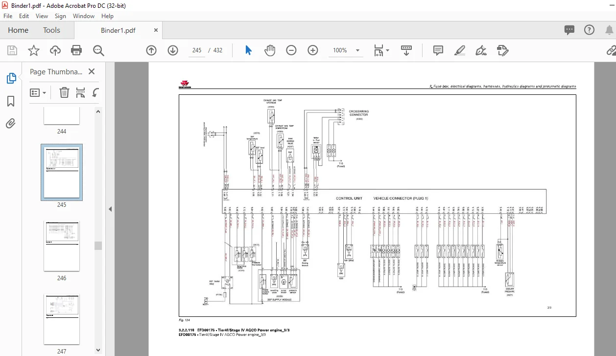
3 2 2 116 EFD00175 – Tier 4f/Stage I V AGCO Роwег engine _ 1/3 3- 159
3 2 2 117 EFD00175- Tier 4f/Stage I V AGCO Роwег engine _2/3 3- 160
3 2 2 118 EFD00175 – Tier 4f/Stage I V AGCO Роwег engine _3/3 3- 161
3 2 2 119 EFD00175 _8- SC R Technolog y 3- 162
3 2 2 12 0 EFD00176_ 11 – Electroh ydraulic Ыocks 3- 163
3 2 2 12 1 EFD00178_5 – Speed Steer steering 3- 164
3 2 2 12 2 EFD00183 _2 – lmplement attachment without lsobus 3- 165
3 2 2 12 3 EFD00184 _3 – AgCommand ™ 3- 166
З З Harnesses З-169
3 3 1 lndex section 3- 169
3 3 1 1 ldentification of harnesses 3- 169
3 3 1 2 ldentification tаЫе fог саЫе colors 3- 17 2
3 3 2 Harnesses 3- 175
3 3 2 1 FA l 2 00 – Engine harness – ACW012 081 1/4 3- 175
3 3 2 2 FA l 2 00 – Engine harness – ACW012 081 2/4 3- 176
3 3 2 3 FA l 2 00 – Engine harness – ACW012 081 3/4 3- 177
Technician Service Book- MF 5700 SL
АСТОО21580
ТаЬ/е of contents
3 3 2 4 FAl 2 00 – Engine ha rness -ACW01 2 08 1 _ 4/ 4 3-178
3 3 2 5 FAl 2 01 – F ront headlights ha rness -ACW03 0858_1 /2 3-179
3 3 2 6 FAl 2 01 – F ront headlights ha rness -ACW03 0858_2/2 3-18 0
3 3 2 7 FAl 2 02 – Suspended f ront axle ha rness -ACW03 08 38 _1 /2 3-181
3 3 2 8 FAl 2 02 – Suspended f ront a xle ha rness -ACW03 08 38_2/2 3-18 2
3 3 2 9 FAl 2 0 3 – T ransmissi on ha rness e xte rnal G T A 2 550 -ACW076051_ 1/ 3 3-18 3
3 3 2 1 О FAl 2 0 3 – T ransmissi on ha rness e xte rnal G T A 2 550 -ACW076051 _2/3 3-18 4
3 3 2 1 1 FAl 2 0 3 – T ransmissi on ha rness e xte rnal G T A 2 550 -ACW076051_3/ 3 3-185
3 3 2 1 2 FAl 2 0 3 – T ransmissi on ha rness e xte rnal G T A 2 550 -ACW076057 _ 1/ 2 3-186
3 3 2 1 3 FAl 2 0 3 – T ransmissi on ha rness e xte rnal G T A 2 550 -ACW076057 2/ 2 3-18 7
3 3 2 1 4 FAl 2 1О – Са Ь t ransmissi on ha rness Dyna-6 sh ort c ons ole –
ACW005780_ 1/8 3-188
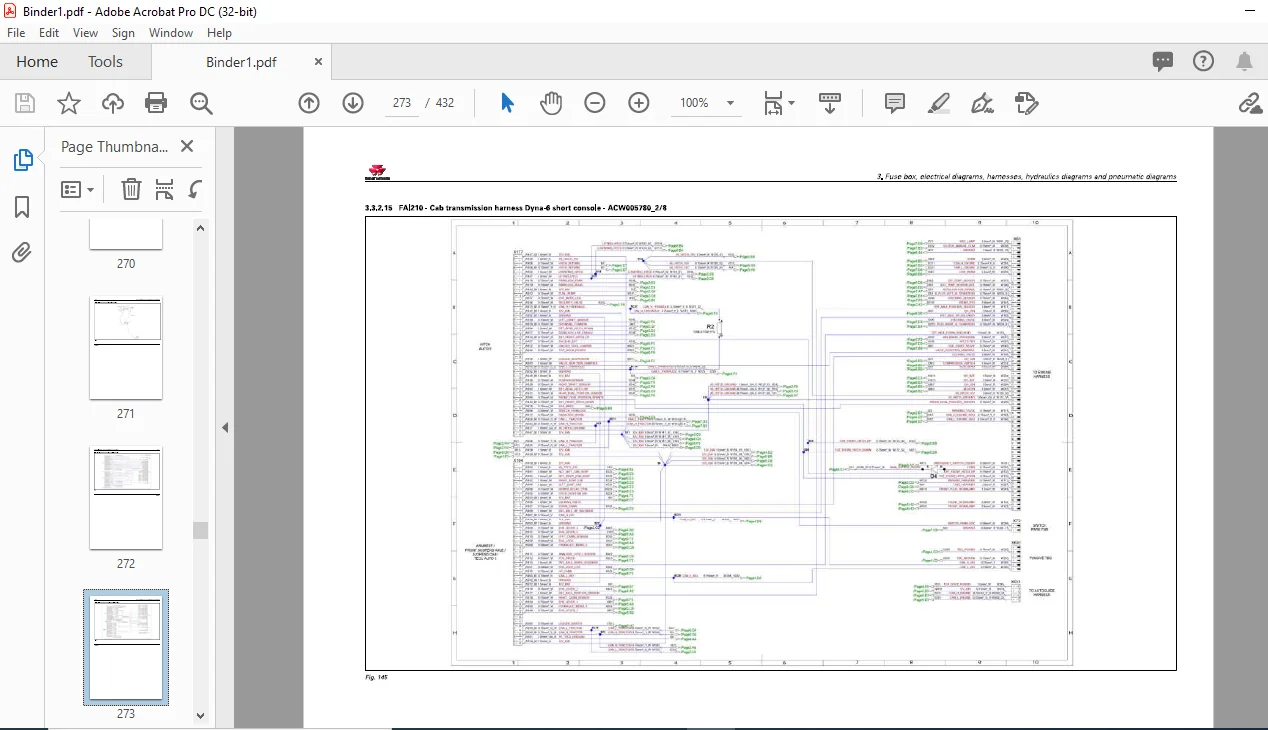
3 3 2 15 FAl 2 1О – Са Ь t ransmissi on ha rness Dyna-6 sh ort c ons ole –
ACW00578 0_2/8 3-189
3 3 2 16 FAl 2 1О – Са Ь t ransmissi on ha rness Dyna-6 sh ort c ons ole –
ACW00578 0_3/8 3-190
3 3 2 17 FAl 2 1О – Са Ь t ransmissi on ha rness Dyna-6 sh ort c ons ole –
ACW00578 0_ 4/8 3-191
3 3 2 18 FAl2 1 О – Са Ь t ransmissi on ha rness Dyna-6 sh ort c ons ole –
ACW00578 0_5/8 3-19 2
3 3 2 19 FAl 2 1О – Са Ь t ransmissi on ha rness Dyna-6 sh ort c ons ole –
ACW00578 0_6/8 3-19 3
3 3 2 2 0 FAl 2 1О – Са Ь t ransmissi on ha rness Dyna-6 sh ort c ons ole –
ACW00578 0_7 /8 3-19 4
3 3 2 2 1 FAl 2 1О – Са Ь t ransmissi on ha rness Dyna-6 sh ort c ons ole –
ACW00578 0_8/8 3 -195
3 3 2 2 2 FAl 2 1О – Са Ь t ransmissi on ha rness Dyna-6 l ong c ons ole –
ACW00578 4_ 1/8 3-196
3 3 2 2 3 FAl 2 1О – Са Ь t ransmissi on ha rness Dyna-6 l ong c ons ole –
ACW00578 4_2/8 3-197
3 3 2 2 4 FAl 2 1О – Са Ь t ransmissi on ha rness Dyna-6 l ong c ons ole –
ACW00578 4_3/8 3-198
3 3 2 25 FAl 2 1О – Са Ь t ransmissi on ha rness Dyna-6 l ong c ons ole –
ACW00578 4_ 4/8 3-199
3 3 2 26 FAl 2 1О – Са Ь t ransmissi on ha rness Dyna-6 l ong c ons ole –
ACW00578 4_5/8 3-2 00
3 3 2 2 7 FAl 2 1О – Са Ь t ransmissi on ha rness Dyna-6 l ong c ons ole –
ACW00578 4_6/8 3-2 01
3 3 2 28 FAl 2 1О – Са Ь t ransmissi on ha rness Dyna-6 l ong c ons ole –
ACW00578 4_7/8 3-2 02
3 3 2 29 FAl 2 1О – Са Ь t ransmissi on ha rness Dyna-6 l ong c ons ole –
ACW00578 4_8/8 3-2 0 3
3 3 2 3 0 FAl 2 1О – Са Ь t ransmissi on ha rness Dyna-4 sh ort c ons ole –
ACW02 1 492 _1 / 8 3-2 04
3 3 2 3 1 FAl 2 1О – Са Ь t ransmissi on ha rness Dyna-4 sh ort c ons ole –
ACW02 1 49 2 _2/8 3-2 05
3 3 2 3 2 FAl 2 1О – Са Ь t ransmissi on ha rness Dyna-4 sh ort c ons ole –
ACW02 1 49 2 _3/8 3-2 06
3 3 2 3 3 FAl 2 10 – Са Ь t ransmissi on ha rness Dyna-4 sh ort c ons ole –
ACW02 1 49 2 _ 4/8 3-2 07
3 3 2 3 4 FAl 2 10 – Са Ь t ransmissi on ha rness Dyna-4 sh ort c ons ole –
ACW02 1 49 2 _5/8 3-2 08
3 3 2 35 FAl 2 10 – Са Ь t ransmissi on ha rness Dyna-4 sh ort c ons ole –
ACW02 1 49 2 _6/8 3-2 09
3 3 2 36 FAl 2 10 – Са Ь t ransmissi on ha rness Dyna-4 sh ort c ons ole –
ACW02 1 49 2 _7/8 3-2 10
3 3 2 3 7 FAl 2 1О – Са Ь t ransmissi on ha rness Dyna-4 sh ort c ons ole –
ACW02 1 49 2 _8/8 3-2 1 1
Technician Service Book- M F 5700 SL
АСТОО21580
ТаЬ/е of contents
3 3 2 38 FAl2 1 О – Са Ь transmI ssю n harness Dyna-4 long console –
ACW02 2 3 0 3 _ 1 /7 3-2 1 2
3 3 2 39 FAl2 1 О – Са Ь transmission harness Dyna-4 long console –
ACW02 2 3 0 3 _2/7 3-2 1 3
3 3 2 40 FAl2 1 О – Са Ь transmission harness Dyna-4 long console –
ACW02 2 3 0 3 _3/7 3-2 1 4
3 3 2 41 FAl2 1 О – Са Ь transmission harness Dyna-4 long console –
ACW02 2 3 0 3 _ 4/7 3-2 15
3 3 2 42 FAl2 1 О – Са Ь transmission harness Dyna-4 long console –
ACW02 2 3 0 3 _5/7 3-2 16
3 3 2 43 FAl2 1 О – Са Ь transmission harness Dyna-4 long console –
ACW02 2 3 0 3 _6/7 3-2 17
3 3 2 44 FAl2 1 О – Са Ь transmission harness Dyna-4 long console –
ACW02 2 3 0 3 _7/7 3-2 18
3 3 2 45 FAl2 1 2 – Lighting harness NA – 4 3 77 26 3 _ 1/ 3 3 -2 19
3 3 2 46 FAl2 1 2 – Lighting harness NA- 4 3 77 26 3 _2 / 3 3-2 2 0
3 3 2 47 FAl2 1 2 – Lighting harness NA- 4 3 77 26 3 _3 / 3 3-2 2 1
3 3 2 48 FAl2 1 2 – Lighting harness ЕАМЕ – 4 3 77 26 4_ 1/ 3 3-2 2 2
3 3 2 49 FAl2 1 2 – Lighting harness ЕАМЕ – 4 3 77 26 4_2/ 3 3-2 2 3
3 3 2 50 FAl2 1 2 – Lighting harness ЕАМЕ – 4 3 77 26 4_3/3 3-2 2 4
3 3 2 51 FAl2 19- Са Ь interior power socket harness – 429057 4_1/ 2 3-2 25
3 3 2 52 FAl2 19 – Са Ь interior power socket harness – 429057 4_2/ 2 3-2 26
3 3 2 53 FAl2 19 – Са Ь interior power socket harness – 4290575_ 1/ 2 3-2 2 7
3 3 2 54 FAl2 19 – Са Ь interior power socket harness – 4290575_2/ 2 3-2 28
3 3 2 55 FAl2 2 3 – Roof harness standard – 4353 057 1/ 3 3-2 29
3 3 2 56 FAl2 2 3 – Roof harness standard – 4353 057 _2/3 3 -2 3 0
3 3 2 57 FAl2 2 3 – Roof harness standard – 4353 057 3/ 3 3-2 3 1
3 3 2 58 FAl2 25- Electric rear-view mirror harness – 435262 2_1 /2 3-2 3 2
3 3 2 59 FAl2 25 – Electric rear-view mirror harness – 43526 2 2 _2/2 3-2 3 3
3 3 2 60 FAl2 2 7- Automatic air conditioning harness -roof- 435262 1_1 /3 3-2 3 4
3 3 2 61 FAl2 2 7- Automatic air conditioning harness -roof- 435262 1_2/3 3-2 35
3 3 2 62 FAl2 2 7- Automatic air conditioning harness -roof- 435262 1_3/3 3-2 36
3 3 2 6 3 FAl2 28 -Number plate lighting harness – 4353 107 1/ 2 3-2 3 7
3 3 2 6 4 FAl2 28 -Number plate lighting harness – 4353 107 _2/2 3-2 38
3 3 2 65 FAl 2 28 – Number plate lighting harness number plate оп flat roof –
4 38 2 2 3 4_ 1/ 2 3-2 39
3 3 2 66 FAl 2 28 – Number plate lighting harness number plate оп flat roof –
438 2 2 3 4_2/ 2 3-2 40
3 3 2 67 FAl2 40 – + 1 2 V permanent fuse Ьох harness -ACW0 l 5790 3-2 41
3 3 2 68 FAl253 – Hand rail harness – 43 79 3 52 _ 1/ 2 3-2 42
3 3 2 69 FAl253 – Hand rail harness – 43 79 3 52 _2/2 3-2 43
3 3 2 70 FAl261 – lso bus harness – 4353 1 3 0_ 1/ 2 3-2 44
3 3 2 71 FAl261 – lso bus harness – 4353 1 3 0_2/ 2 3-2 45
3 3 2 7 2 FAl261 – lso bus harness – 4353 1 3 3 3-2 46
3 3 2 7 3 FAl26 2 -Auto-Guide™ engine harness – 42968 1 О _ 1/ 2 3-2 47
3 3 2 7 4 FAl26 2 -Auto-Guide™ engine harness – 42968 10_2/ 2 3-2 48
3 3 2 75 FAl26 3 -Auto-Guide™ са Ь adapter harness – 43539 36_ 1/ 2 3-2 49
3 3 2 76 FAl26 3 -Auto-Guide™ са Ь adapter harness – 43539 36_2/2 3-250
3 3 2 77 FAl265 – Pneumatic braking harness Dyna-6 -ACW0 l 691 3 _1 /2 3-251
3 3 2 78 FAl265 – P neumatic braking harness Dyna-6 -ACW0 l 691 3 _2/2 3-252
3 3 2 79 FAl2 7 3 – Front linkage harness – Power socket – 438 7 2 29_ 1/ 2 3-253
3 3 2 8 0 FAl2 7 3 – Front linkage harness – Power socket – 438 7 2 29_2/2 3-254
3 3 2 8 1 FAl28 3 – T op Dock harness – 43 77536_ 1/ 2 3-255
3 3 2 8 2 FAl28 3 – T op Dock harness – 43 77536_2/2 3-256
3 3 2 8 3 FAl 28 7 – ALO loader harness e xternal without multi-function armrest –
4 3 78 79 4_ 1/ 2 3-257
3 3 2 8 4 FAl 28 7 – ALO loader harness e xternal without multi-function armrest –
4 3 78 79 4_2/2 3-258
Technician Service Book- MF 5700 SL
АСТОО21580
3 4
ТаЬ/е of contents
3 3 2 85 FAl 28 7 – ALO loader harness internal without multi-function armrest –
43 788 79_ 1 /2 3-259
3 3 2 86 FAl 28 7 – ALO loader harness internal without multi-function armrest –
43 788 79_2/2 3-260
3 3 2 8 7 FAl 290 -Non-lso bus implement connector harness – 4296 266_ 1/ 2 3-261
3 3 2 88 FAl 290 -Non-lso bus implement connector harness – 4296 266_2/ 2 3-26 2
3 3 2 89 FAl 292 -NA indicator harness – 4 35098 7 3-26 3
3 3 2 90 FAl 292 -NA indicator harness – 4355519_ 1/ 2 3-26 4
3 3 2 91 FAl 292 -NA indicator harness – 4355519_2/2 3-265
3 3 2 9 2 FAl 292 -NA indicator harness – 4 3 7678 0_ 1/ 2 3-266
3 3 2 9 3 FAl 292 -NA indicator harness – 4 3 7678 0_2/2 3-267
3 3 2 9 4 FAl 2 9 3 – ЕАМЕ indicator harness – 4 350988 3-268
3 3 2 95 FAl 2 9 3 – ЕАМЕ indicator harness – 435552 0_ 1/ 2 3-269
3 3 2 96 FAl 2 9 3 – ЕАМЕ indicator harness – 435552 0_2/ 2 3-2 70
3 3 2 97 FAl 294 -Additional heater harness – 42993 2 7_ 1 /2 3 -2 71
3 3 2 98 FAl 294- Additional heater harness – 42993 2 7_ 2/2 3-2 72
3 3 2 99 FAl 299 – Batter y isolator harness -ACW01 2 3 2 4 3-2 73
3 3 2 100 FAl 299 – Batter y isolator harness -ACW01 2 3 26 3-2 7 4
3 3 2 101 FAl 299 – Batter y isolator harness -ACW01 2 368_1 /2 3-2 75
3 3 2 102 FAl 299 – Batter y isolator harness -ACW01 2 368 _2/2 3-2 76
3 3 2 10 3 FAl 3 00 -Air conditioning shunt harness – 4353 106 3-2 77
3 3 2 104 FAl 3 07 – Datatronic 4 harness – 4353638_1 /2 3-2 78
3 3 2 105 FAl 3 07 – Datatronic 4 harness – 43536 38 _2/2 3-2 79
3 3 2 106 FAl 3 1 1 – Batter y/starter po siti ve саЫе harness -ACW01 2 3 2 0 3-280
3 3 2 107 FAl 3 1 2 – CaЬ/starter negati ve саЫе harness -ACW01 2 366 3-28 1
3 3 2 108 FAl 3 1 4 -Alternator harness -ACW01 2 08 4_ 1/ 2 3 -28 2
3 3 2 109 FAl 3 1 4 -Alternator harness -ACW01 2 08 4_2/ 2 3-28 3
3 3 2 11 О FAl 3 17 – Vistronic harness -ACW0253 38_1 /2 3-28 4
3 3 2 1 1 1 FAl 3 17 – Vistronic harness -ACW0253 38 _2/2 3-285
3 3 2 1 1 2 FAl3 25 – Роwег take-off electric selector harness – 2-speed –
438 1659_1/ 2 3-286
3 3 2 1 1 3 FAl3 25 – Роwег take-off electric selector harness – 2-speed –
438 1659_2/ 2 3-28 7
3 3 2 1 1 4 FAl3 25 – Роwег take-off electric selector harness – 3-speed –
438 1660_1/ 2 3-288
3 3 2 115 FAl3 25 – Роwег take-off electric selector harness – 3-speed –
438 1660_2/2 3-289
3 3 2 1 16 FAl 354 – External loader harness – 4 3 7 4651_ 1/ 2 3-290
3 3 2 117 FAl 354 – External loader harness – 4 3 7 4651 _2/ 2 3-291
3 3 2 1 18 FAl 3 56 – Mid Mounted са Ь harness – 4353915_ 1/ 2 3-292
3 3 2 1 19 FAl 3 56 – Mid Mounted са Ь harness – 4353915_2/ 2 3-2 9 3
3 3 2 1 2 0 FAl 3 57 – External Mid Mounted harness – 4353 71 3 _ 1/ 2 3-294
3 3 2 1 2 1 FAl 3 57 – External Mid Mounted harness – 4353 71 3 _2/2 3-295
3 3 2 1 2 2 FAl 360 – T op Dock harness – 4 3 7753 7-1/ 2 3-296
3 3 2 1 2 3 FAl 360 – T op Dock harness – 4 3 7753 7-2/2 3-297
Hydraulics diagrams З-299
3 4 1 H ydraulics diagrams 3-3 01
3 4 1 1 H F D01048 – H ydraulics diagram: all options, with Mid Mounted, Open
Center 57 Umin 3-3 01
3 4 1 2 H F D01049 – H ydraulics diagram: all options, without Mid Mounted Open
Center 57 Umin 3 -3 0 2
3 4 1 3 H F D01050 – H ydraulics diagram: all options, with Mid Mounted Open
Center 100 Umin 3-3 0 3
3 4 1 4 H F D01051 – H ydraulics diagram all options, without Mid Mounted Open
Center 100 Umin 3-3 04
3 4 1 5 H F D01052 – H ydraulics diagram: all options with Mid Mounted Load
Sensing 3-3 05
Technician Service Book- MF 5700 SL
АСТОО21580
ТаЬ/е of contents
3 4 1 6 H F D01053 – H ydraulics diagram: all options without Mid Mounted Load
Sensing 3-3 06
3 4 1 7 H F D02 01 1 – Load Sensing standard steering system h ydraulics diagram 3-3 07
3 4 1 8 H F D02 01 2 – Load Sensing Auto-Guide™/Auto-Guide™ steering system
h ydraulics diagramSpeedSteer 3-3 08
3 4 1 9 H F D0 3 067 – H ydraulics diagram: Open Center tractor braking with trailer
brake 3-3 09
3 4 1 1 О H F D0 3 068 – H ydraulics diagram: Open Center tractor braking without
trailer Ьгаkе 3-3 1 О
3 4 1 1 1 H F D0 3 069 – H ydraulics diagram: Load Sensing tractor braking with
tгailer Ьгаkе 3-3 1 1
3 4 1 1 2 Н F D0 3 070 – H ydraulics diagram: Load Sensing tractor braking without
trailer Ьгаkе 3-3 1 2
3 5 Pneumatic diagrams 3-313
3 5 1 P neumatic diagrams 3-3 15
3 5 1 1 P F D01009 – T railer brake pneumatic diagram 3-3 15
4 Adjustments, Ьleeding and calibrations 4-1
4 1 Bleeding 4-3
4 1 1 Bleeding the main brake system 4-3
4 1 1 1 Bleeding procedure 4-4
4 1 2 Bleeding the tгailer Ьгаkе system 4-5
4 2 Calibrations 4-6
4 2 1 Cali bration of the clutch pedal sensor 4-6
4 2 2 Cali bration of the throttle pedal sensor 4-6
4 2 3 Calibrating the rеаг linkage 4-7
4 2 4 Calibrate the suspended front a xle 4-9
4 2 5 Cali brating the automatic disengagement of the differential and 4-wheel dri ve 4-1 О
4 2 6 Cali bration of the forward-tra vel le ver 4-1 2
4 2 7 Forward speed calibration 4-15
4 2 8 Cali bration of the Dyna-4 and Dyna-6 PowerS huttle tгansmission 4-15
4 2 9 Cali bration of electroh ydraulic Ыо сk 4-18
4 2 1 О Cali brations to Ь е carried out using the diagnostic tool 4-19
4 2 10 1 Calibration of the FingerТ IР controls оп the armrest 4-19
4 2 10 2 Jo ystick calibration 4-2 3
4 2 10 3 Calibrating the hand throttle 4-26
4 2 10 4 Cali brating the depth control thumb wheel 4-29
Questions? Email us: [email protected]
IMAGES PREVIEW OF THE MANUAL:
PLEASE NOTE:
- This is the SAME exact manual used by your dealers to fix your vehicle.
- The same can be yours in the next 2-3 mins as you will be directed to the download page immediately after paying for the manual.
- Any queries / doubts regarding your purchase, please feel free to contact [email protected]
S.V