Massey Ferguson SA MF2200 Series 2240 2250 2260 2270 2270XD 2290 Large Square Baler Service Manual
Original price was: $68.95.$31.95Current price is: $31.95.
Massey Ferguson SA MF2200 Series 2240 2250 2260 2270 2270XD 2290 Large Square Baler Service Manual – PDF DOWNLOAD
Description
Massey Ferguson SA MF2200 Series 2240 2250 2260 2270 2270XD 2290 Large Square Baler Service Manual – PDF DOWNLOAD
DESCRIPTION:
Massey Ferguson SA MF2200 Series 2240 2250 2260 2270 2270XD 2290 Large Square Baler Service Manual – PDF DOWNLOAD
General information
Introduction to this service manual
This service manual gives information from engineering tests, operating data, and the latest service techniques at the time of publication. Read this service manual carefully before doing any service on the machine. The photos and illustrations used in this service manual were current at the time of publication. Production changes can cause machines to vary from the photos and the illustrations. The manufacturer reserves the right to redesign and change machines as necessary without notification.
Units of measurement
Measurements are given in metric units followed by the equivalent in U S units. Hardware sizes are given in millimeters for metric hardware and inches for U S hardware.
Table of contents
This manual has a table of contents at the front. The table of contents shows the divisions. The individual divisions also have a table of contents.
Page numbers
All pages have two numbers, such as 01-25. The first number shows the divis ion. The second number shows the page in the division. Page numbers occur on the lower right-hand or lower left-hand corner of each page.
TABLE OF CONTENTS:
Massey Ferguson SA MF2200 Series 2240 2250 2260 2270 2270XD 2290 Large Square Baler Service Manual – PDF DOWNLOAD
1 General 1-1
1 1 General information 1-5
1 1 1 lntroduction to this service manual 1-5
1 1 2 Units of measurement 1-5
1 1 3 Т аЫе of contents 1-5
1 1 4 Page numbers 1-5
1 1 5 lnstalling а stake nut 1-5
1 1 6 lnstalling а gib key 1-6
1 1 7 Removing а gib key 1-6
1 1 8 lnstalling an eccentric locking collar 1-7
1 1 9 Removing an eccentric locking collar 1-8
1 2 Safety 1-9
1 2 1 Safety alert symbol 1-9
1 2 2 Safety messages 1-9
1 2 3 lnformational messages 1-9
1 2 4 Safety signs 1-1 О
1 2 5 Safety warnings 1-1О
1 2 6 А word to the technician 1-1О
1 2 7 The service manual 1-1 1
1 2 8 The operator manual 1-1 2
1 2 9 Toolbox 1-1 2
1 2 10 Operation 1-12
1 2 1 1 Travel on puЬlic roads 1-17
1 2 1 2 Maintenance 1-1 8
1 3 Specifications 1-23
1 3 1 Dimensions and weights 1-2 3
1 3 2 Drive system specifications 1-2 5
1 3 3 Shearbolt specifications 1-27
1 3 4 Hydraulic specifications -on board 1-2 8
1 3 5 Pickup specifications 1-2 9
1 3 6 Rotor cutter specifications, if equipped 1-3 0
1 3 7 Packer specifications 1-3 2
1 3 8 Packer/cutter specification, if equipped 1-3 3
1 3 9 Stuffer specifications 1-3 4
1 3 1О Plunger specifications 1-3 4
1 3 1 1 Twine specifications 1-3 5
1 3 1 2 Knotter and needle specifications 1-3 6
1 3 1 3 Bale chamber tension specifications 1-3 7
1 3 1 4 Ejector specifications 1-3 8
1 3 1 5 Roller bale chute specifications, if equipped 1-3 9
1 3 1 6 Lamp specification 1-4 0
1 3 17 Knotter lubrication pump specifications 1-4 0
1 3 1 8 Chain lubrication pump specifications, if equipped 1-4 1
1 3 1 9 Lubricants and capacities 1-4 2
1 3 20 Tire specifications 1-4 4
1 3 2 1 Brake specifications, if equipped 1-4 6
1 3 2 2 Maximum speed 1-4 7
1 3 2 3 Tractor requirements 1-4 7
1 3 2 4 Noise levels 1-4 9
1 4 Bolt torque values 1-50
Large square ba/er
4283515М2
ТаЬ/е of contents
1 5 Machine indentification 1-52
1 5 1 Serial number plate location 1-5 2
1 5 2 Serial number description 1-5 3
1 6 Machine components 1-55
1 6 1 Outside view -left-hand side 1-5 5
1 6 2 Outside view -right-hand side 1-5 5
1 6 3 lnside view -left-hand side 1-5 6
1 6 4 lnside view -right-hand side 1-5 7
1 6 5 Description of operation 1-5 8
1 7 Lubrication points 1-60
1 7 1 Driveline lubrication and maintenance 1-6 0
1 7 2 Lubricating the hitch ball, if equipped 1-6 2
1 7 3 Lubricating the main drive slip clutch 1-6 3
1 7 4 Lubricating the overrunning clutch 1-6 3
1 7 5 Lubricating the flywheel bearing 1-6 3
1 7 6 Lubricating the connecting rods 1-6 4
1 7 7 Lubricating the packer crank bearings 1-6 5
1 7 8 lnspecting the packer crank bearings 1-6 5
1 7 9 Lubricating the packer/cutter crank bearings 1-6 5
1 7 1 О lnspecting the packer/cutter crank bearings 1-6 6
1 7 1 1 Lubricating the cutter rotor clutch, if equipped 1-6 6
1 7 1 2 Lubricating the anchor for the rotor cutter chain tensioner 1-6 7
1 7 1 3 Lubricating the rotor cutter bearings 1-6 7
1 7 1 4 Lubricating the main drive sprocket 1-6 8
1 7 1 5 Lubricating the stuffer drive 1-6 8
1 7 1 6 Lubricating the knotter/needle clutch 1-6 9
1 7 1 7 Lubricating the brake linkage 1-6 9
1 7 1 8 Lubricating the tandem axle pivot bushings 1-7 0
1 7 1 9 Lubricating the metering wheel shaft 1-7 0
1 7 2 0 Lubricating the six twine knotter center fitting 1-7 0
1 7 2 1 Lubricating the tucker arm and twine arm cam rollers 1-7 1
1 7 2 2 Lubricating the bale density cylinders 1-7 2
1 7 2 3 Lubricating the packer clutch 1-7 2
1 7 2 4 Lubricating the main packer/cutter crank bearing 1-7 2
1 7 2 5 Lubricating the packer/cutter chain tensioner 1-7 3
1 7 2 6 Lubricating the pickup overrunning clutch 1-7 3
1 7 2 7 Lubricating the pickup linkage roller 1-7 3
1 7 2 8 Lubricating the pickup spring pivot 1-7 4
1 8 Connecting to the tractor – СЕ 1-75
1 8 1 Removing the shipping bracket 1-7 5
1 8 2 Hitch component identification 1-7 5
1 8 3 Baler height setting 1-7 5
1 8 4 Tractor setup dimensions with an 8 0 mm (3 1 5 in) ball hitch, а СЕ spherical ball
hitch, ог а 5 0 mm (2 in) ring hitch 1-7 6
1 8 5 Tractor setup dimensions with а 4 0 mm (1 6 in) high ring hitch 1-7 6
1 8 6 lnstalling the machine hitch 1-7 7
1 8 7 Connecting the machine hitch to the tractor drawbar 1-7 9
1 8 8 Connecting а 5 0 mm (2 in) ring hitch to the tractor 1-8 0
1 8 9 Connecting an 8 0 mm (3 1 5 in) ball hitch to the tractor 1-8 1
1 8 1 О Connecting а 4 0 mm (1 6 in) high ring hitch to the tractor 1-8 1
1 8 1 1 Operating а hydraulic tongue jack 1-8 1
1 8 1 2 lnstalling the safety transport chain 1-8 2
1 8 1 3 Constant velocity implement driveline, if equipped 1-8 2
1 9 Connecting to the tractor – NA 1-87
1 9 1 Removing the shipping bracket 1-8 7
1 9 2 Power takeoff types 1-8 7
Large square ba/er
4283515М2
ТаЬ!е of contents
1 9 3 Tractor setup dimensions with Туре 2 ог Туре 3 power takeoff 1-8 7
1 9 4 Baler height setting 1-8 8
1 9 5 Checking and adjusting the hitch ball 1-8 8
1 9 6 lnstalling the machine hitch 1-9 0
1 9 7 Connecting the machine hitch to the tractor drawbar 1-9 1
1 9 8 Operating а hydraulic tongue jack 1-9 2
1 9 9 lnstalling the safety transport chain 1-9 2
1 9 1О Equal angle implement driveline, if equipped 1-9 3
1 1 О Checklists 1-97
1 10 1 Daily checklist 1-9 7
1 10 2 lnspection after the first hour of operation 1-9 7
1 11 Lighting and reflectors – СЕ 1-98
1 1 1 1 Lighting and reflectors 1-9 8
1 12 Lighting and reflectors – NA 1-100
1 1 2 1 Lighting and reflectors 1-10 0
1 13 Baler operation 1-102
1 1 3 1 Preparing to bale 1-10 2
1 1 3 2 Starting the baler 1-10 2
1 1 3 3 Baling the first bale 1-10 3
1 1 3 4 Baling 1-10 4
1 1 3 5 Stopping the baler 1-10 4
1 14 Preparing to road or move оп а trailer 1-105
1 15 Lifting and tie down 1-108
1 1 5 1 Lifting а baler correctly 1-10 8
1 1 5 2 Lifting points 1-10 8
1 1 5 3 Tie down points 1 -1 0 9
1 16 Air brake pressure release 1-111
1 17 Disconnecting the tractor 1-112
2 Main frame 2-1
2 1 Wheel and tire specifications 2-З
2 1 1 Tire specifications 2-3
2 1 2 Removing а wheel 2-4
2 1 3 lnstalling а wheel 2-5
2 2 Single axle 2-6
2 2 1 Removing an axle shaft without brakes 2-6
2 2 2 Removing the axle shaft with brakes 2-6
2 2 3 lnspecting an axle 2-6
2 2 4 lnstalling an axle shaft without brakes 2-7
2 2 5 lnstalling an axle shaft with brakes 2-7
2 3 Tandem axle 2-8
2 3 1 Tandem axle steering lock 2-8
2 3 2 Removing the геаг tandem axle 2-8
2 3 3 Removing the front tandem axle 2-9
2 3 4 lnspecting an axle 2-10
2 3 5 lnstalling the rear tandem axle 2-1 О
2 3 6 lnstalling the front tandem axle 2-1 2
2 3 7 Adjusting the геаг wheel alignment 2-1 2
2 4 Wheel bearing 2-14
2 4 1 Checking а wheel bearing 2-1 4
2 4 2 Removing the wheel bearings -single axle without brakes 2-1 4
2 4 3 Removing the wheel bearings -single axle with brakes ог tandem axle 2-1 4
2 4 4 lnspecting the wheel bearing 2-1 5
2 4 5 lnstalling the wheel bearings -single axle without brakes 2-1 5
2 4 6 lnstalling the wheel bearings -single axle with brakes and all tandem axles 2-1 6
Large square ba/er
4283515М2
ТаЬ/е of contents
2 5 Axle frame group 2-18
2 5 1 Removing the axle frame -single axle without brakes 2-1 8
2 5 2 Removing the axle frame -single axle with hydraulic brakes 2-1 8
2 5 3 Removing the axle frame -single axle with air brakes 2-1 9
2 5 4 Removing the axle frame -tandem axle without brakes 2-1 9
2 5 5 Removing the axle frame -tandem axle with hydraulic brakes 2-20
2 5 6 Removing the axle frame -tandem axle with air brakes 2-2 1
2 5 7 lnstalling the axle frame -single axle without brakes 2-2 1
2 5 8 lnstalling the axle frame -single axle with hydraulic brakes 2-2 2
2 5 9 lnstalling the axle frame -single axle with air brakes 2-2 2
2 5 1О lnstalling the axle frame -tandem axle without brakes 2-2 3
2 5 1 1 lnstalling the axle frame -tandem axle with hydraulic brakes 2-2 3
2 5 1 2 lnstalling the axle frame -tandem axle with air brakes 2-2 4
2 5 1 3 Removing the leaf spring assemЬly 2-2 4
2 5 1 4 lnspecting the leaf spring assemЫy 2-2 5
2 5 1 5 lnstalling the leaf spring assemЬly 2-2 6
2 6 Brakes 2-27
2 6 1 Brake system inspection 2-27
2 6 2 Connecting the machine hydraulic brake hoses to the tractor 2-27
2 6 3 Bleeding the hydraulic brake system 2-27
2 6 4 lnspecting the brake lining 2-2 8
2 6 5 Replacing the brake linings 2-2 8
2 6 6 Adjusting the brakes 2-2 9
2 6 7 Rubber brake wiper 2-2 9
3 Drive system 3-1
3 1 lmplement driveline 3-3
3 1 1 Power takeoff types 3-3
3 1 2 Equal angle implement driveline, if equipped 3-3
3 1 3 Constant velocity implement driveline, if equipped 3-5
3 1 4 Removing the implement driveline (IDL} 3-1О
3 1 5 lnstalling the implement driveline (IDL) 3-1 1
3 1 6 Replacing а pawl оп а quick disconnect yoke 3-1 3
3 1 7 Replacing the cross and bearing 3-1 6
3 2 Main drive shaft З-25
3 2 1 Driveline trouЬleshooting 3-2 5
3 2 2 Main drive shaft 3-2 5
3 2 3 Removing the main drive shaft 3-2 6
3 2 4 lnspecting the main drive shaft 3-2 8
3 2 5 lnstalling the main drive shaft 3-2 9
3 3 Main drive clutch 3-30
3 3 1 Main drive slip clutch adjustment 3-3 0
3 3 2 Lubricating the main drive slip clutch 3-3 1
3 3 3 Removing the main drive clutch 3-3 1
3 3 4 DisassemЫing the main drive clutch 3-3 1
3 3 5 lnspecting the main drive clutch 3-3 2
3 3 6 AssemЫing the main drive clutch 3-3 4
3 3 7 DisassemЫing the main drive overrunning clutch 3-3 5
3 3 8 lnspecting the main drive overrunning clutch 3-3 5
3 3 9 AssemЫing the main drive overrunning clutch 3-3 6
3 3 1О lnstalling the main drive clutch 3-3 6
3 4 Flywheel 3-37
3 4 1 Flywheel brake 3-3 7
3 4 2 lnspecting the flywheel brake lining 3-3 7
3 4 3 Replacing the flywheel shearbolt 3-3 8
3 4 4 Shearbolt trouЬleshooting 3-3 9
Large square ba/er
4283515М2
ТаЬ!е of contents
3 4 5 Removing the flywheel 3-4 1
3 4 6 lnspecting the flywheel 3-4 3
3 4 7 lnspecting the pinion seal 3-4 4
3 4 8 Replacing the pinion seal 3-4 4
3 4 9 lnstalling the flywheel 3-4 6
3 5 Auxiliary drive shaft 3-50
3 5 1 Removing the auxiliary drive shaft 3-5 0
3 5 2 lnspecting the auxiliary drive shaft 3-5 1
3 5 3 lnstalling the auxiliary drive shaft 3-5 2
3 6 Gearbox 3-54
3 6 1 Removing the gеагЬох 3-5 4
3 6 2 lnstalling the gеагЬох 3-5 7
3 6 3 8 0х7 0 (2х3), 8 0х9 0 (3х3), 1 2 0х7 0 (2х4), 1 20х9 0 (3х4), and 1 20х9 0 XD (3х4 XD)
gеагЬох components 3-6 1
3 6 4 DisassemЫing а 8 0х7 0 (2х3), 8 0х9 0 (3х3), 1 2 0х7 0 (2х4), 1 20х9 0 (3х4), and
1 20х9 0 XD (3х4 XD) gеагЬох 3-6 3
3 6 5 AssemЫing а 8 0х7 0 (2х3), 8 0х9 0 (3х3), 1 20х7 0 (2х4), 1 20х9 0 (3х4), and 1 20х9 0
XD (3х4 XD) gеагЬох 3-6 7
3 6 6 DisassemЫing а 1 2 0х1 3 0 (4х4) gеагЬох 3-8 3
3 6 7 AssemЫing the 1 20х1 3 0 (4х4) gеагЬох 3-9 0
3 6 8 Adjusting the gеагЬох crank агm bolts 3-9 7
3 6 9 GеагЬох trouЫeshooting 3-9 8
4 Hydraulic system 4-1
4 1 Hydraulic system general information 4-3
4 1 1 Hydraulic reseNoir general information 4-3
4 1 2 Hydraulic components, left-hand side 4-3
4 1 3 Hydraulic components, геаг 4-4
4 1 4 Connecting the machine hydraulic hoses to the tгасtог 4-5
4 2 Bale density circuit 4-6
4 2 1 Bale density circuit description 4-6
4 2 2 Filling the hydraulic system 4-6
4 2 3 Replacing а cartridge 4-6
4 3 Baler control valve assemЬly 4-8
4 3 1 Removing the Ьаlег control valve assemЬly 4-9
4 3 2 lnstalling the Ьаlег control valve assemЬly 4-1 О
4 3 3 DisassemЫing the Ьаlег control valve assemЬly 4-1 1
4 3 4 lnspecting the Ьаlег control valve assemЬly 4-1 3
4 3 5 AssemЫing the Ьаlег control valve assemЬly 4-1 6
4 4 Bale ejector/chute valve 4-20
4 4 1 Bale ejector hydraulic connections 4-20
4 4 2 Bale chute hydraulic connections 4-20
4 4 3 Removing the bale ejector/chute valve 4-2 1
4 4 4 lnstalling the bale ejector/chute valve 4-2 3
4 5 Accumulator auxiliary valve 4-25
4 5 1 Accumulator hydraulic system 4-2 5
4 5 2 Accumulator and bale ejector hydraulic connections 4-2 5
4 5 3 DisassemЫing the accumulator auxiliary valve 4-2 6
4 5 4 lnspecting the accumulator auxiliary valve 4-2 6
4 5 5 AssemЫing the accumulator auxiliary valve 4-2 8
4 6 Pickup lift cylinder 4-29
4 6 1 Pickup lift cylinder components 4-2 9
4 6 2 Removing the pickup lift cylinder 4-2 9
4 6 3 lnstalling the pickup lift cylinder 4-3 0
4 6 4 DisassemЫing the pickup lift cylinder 4-3 1
Large square ba/er
4283515М2
ТаЬ/е of contents
4 6 5 lnspecting the pickup lift cylinder 4-3 2
4 6 6 AssemЫing the pickup lift cylinder 4-3 2
4 7 Bale density cylinders 4-33
4 7 1 Bale density cylinder components 4-3 3
4 7 2 Removing the bale density cylinders 4-3 3
4 7 3 lnstalling the bale density cylinders 4-3 4
4 7 4 DisassemЫing the bale density cylinders 4-3 5
4 7 5 lnspecting the bale density cylinders 4-3 6
4 7 6 AssemЫing the bale density cylinders 4-3 6
4 8 Hydraulic trouЫeshooting 4-38
4 8 1 Testing the load control system -load decrease 4-4 3
4 8 2 Testing the load control system -load increase 4-4 3
5 Electrical system 5-1
5 1 Basic trouЫeshooting information 5-3
5 1 1 Basic trouЫeshooting procedures 5-3
5 1 2 Tools 5-4
5 1 3 Continuity check 5-4
5 1 4 Voltage check 5-5
5 1 5 Testing а solenoid valve 5-6
5 1 6 Testing а coil 5-6
5 2 Connectors 5-8
5 2 1 Machine lamp plug wiring diagram NA 5-8
5 2 2 Machine lamp plug wiring diagram СЕ 5-9
5 2 3 Connecting the control harness plug 5-1О
5 2 4 Connecting the four pin plug, machines with а disconnect brake 5-1 1
5 2 5 Checking а connector 5-1 1
5 2 6 Terminal numbers 5-1 2
5 2 7 Pins and sockets 5-1 2
5 2 8 Replacing а Packard connector 5-1 3
5 2 9 Replacing an АМР connector 5-1 4
5 3 Sensors and switches 5-15
5 3 1 Adjusting sensors and switches 5-2 2
5 3 2 Sensors and switches locations and specifications 5-2 3
5 3 3 Testing а sensor 5-2 5
5 3 4 Testing а switch 5-2 6
5 4 Terminal 5-28
5 4 1 General terminal information 5-2 8
5 4 2 CAN bus system overview 5-3 7
5 4 3 Startup screen 5-3 8
5 4 4 Main work screens 5-3 9
5 4 5 Accumulator (if equipped) 5-5 4
5 4 6 Scale, if equipped 5-5 7
5 4 7 Strokes рег flake 5-5 8
5 4 8 Releasing the bale chamber pressure before ejecting а bale 5-5 9
5 4 9 Releasing the bale chamber pressure 5-6 0
5 4 1 О Machine settings screen 5-6 1
5 4 1 1 Service screen 5-6 5
5 4 1 2 Alarm log screen 5-7 2
5 4 1 3 Machine configuration screen 5-7 3
5 4 1 4 Calibrating the accumulator scale 5-7 4
5 4 1 5 Calibrating the bale length, if equipped 5-7 6
5 4 1 6 Calibrating the roller bale chute scale with an object of а known weight 5-7 8
5 4 1 7 Calibrating the roller bale chute scale with а test bale 5-8 0
5 4 1 8 Calibrating the cutter 5-8 2
5 4 1 9 Work records screen 5-8 2
Large square ba/er
4283515М2
ТаЬ!е of contents
5 4 20 lndicator icons and error number 5-9 0
5 4 2 1 Alarms 5-9 3
5 5 Terminal trouЫeshooting 5-105
6 Bale feeding system 6-1
6 1 General information 6-3
6 1 1 Pickup assemЬly 6-3
6 1 2 Pickup assemЬly operation and settings 6-3
6 1 3 Pickup height 6-4
6 1 4 Adjusting the pickup assemЬly flotation -torsion rod system 6-4
6 1 5 Adjusting the pickup assemЫy flotation -compression spring system 6-5
6 1 6 Adjusting the flotation and the gauge wheels height 6-6
6 2 Chain adjustment 6-7
6 2 1 Adjusting the left-hand pickup chains 6-7
6 2 2 Adjusting the right-hand pickup chains 6-7
6 3 Pickup clutch 6-8
6 3 1 Pickup assemЫy clutch operation 6-8
6 3 2 Pickup assemЬly slip clutch components 6-8
6 3 3 Pickup assemЫy overrunning clutch components 6-8
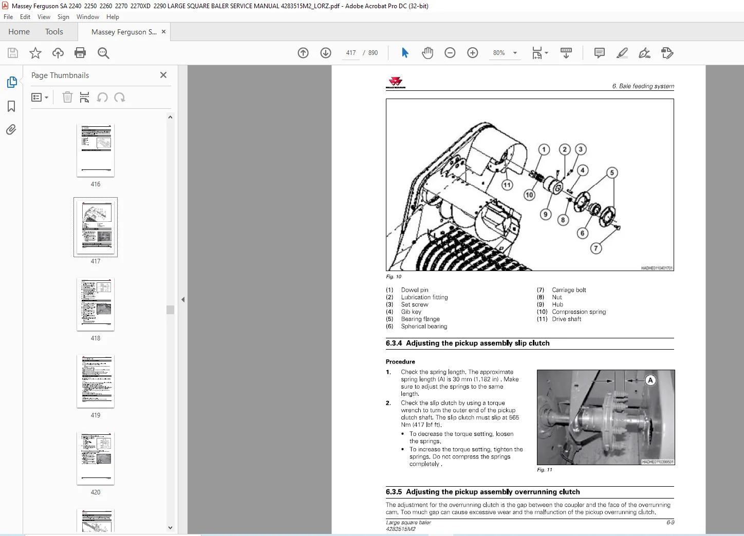
6 3 4 Adjusting the pickup assemЬly slip clutch 6-9
6 3 5 Adjusting the pickup assemЬly overrunning clutch 6-9
6 3 6 Removing the pickup assemЫy clutch 6-1О
6 3 7 DisassemЫing the pickup assemЬly clutch 6-1 1
6 3 8 AssemЫing the pickup assemЬly clutch 6-1 1
6 3 9 lnstalling the pickup assemЫy clutch 6-1 1
6 4 Augers 6-1 з
6 4 1 Augers general information 6-1 3
6 4 2 Left-hand auger components 6-1 3
6 4 3 Removing the primary drive sprocket and the top auger drive sprocket 6-1 4
6 4 4 Removing the bottom augers 6-1 5
6 4 5 Removing the scrapers and wear plates 6-1 6
6 4 6 Right-hand auger components 6-1 6
6 4 7 Removing the right-hand auger 6-17
6 4 8 lnstalling the scrapers 6-1 8
6 4 9 lnstalling the top auger 6-1 9
6 4 1 О lnstalling the bottom auger 6-20
6 5 Reel 6-21
6 5 1 Removing the tines 6-2 1
6 5 2 lnstalling the tines 6-2 1
6 5 3 Removing the cam bearings 6-2 2
6 5 4 lnstalling the cam bearings 6-2 2
6 5 5 Removing the reel bearings 6-2 3
6 5 6 lnstalling the reel bearings 6-2 4
6 5 7 Tine Ьаг components 6-2 5
6 5 8 Removing the tine Ьаг and the bearing 6-2 5
6 5 9 lnstalling the tine bar and the bearing 6-2 9
6 5 1 О Removing the reel 6-3 2
6 5 1 1 lnstalling the reel 6-3 5
6 6 Gauge wheels 6-40
6 6 1 Removing the wheel bearing 6-4 0
6 6 2 lnstalling the wheel bearing 6-4 0
6 6 3 Adjusting the wheel bearing 6-4 1
6 7 TrouЫeshooting 6-42
6 7 1 TrouЫeshooting the pickup assemЫy 6-4 2
Large square ba/er
4283515М2
ТаЬ/е of contents
7 Bale forming system 7-1
7 1 Optional cutter 7-7
7 1 1 Cutterbed 7-7
7 1 2 Rotor cutter 7-3 9
7 1 3 Cutter/packer 7-4 0
7 1 4 Gearbox 7-4 1
7 1 5 Slip cluch and drive chain 7-4 9
7 2 Packer 7-53
7 2 1 Adjusting the packer chain 7-5 3
7 2 2 Adjusting the packer clutch 7-5 3
7 2 3 DisassemЫing the packer clutch 7-5 4
7 2 4 lnspecting the packer clutch 7-5 4
7 2 5 AssemЫing the packer clutch 7-5 5
7 2 6 TrouЫeshooting the packer clutch 7-5 5
7 2 7 Removing the packer fingers 7-5 6
7 2 8 Packer crank components 7-5 7
7 2 9 lnstalling the packer fingers 7-5 8
7 2 1 О Removing the packer finger links 7-5 9
7 2 1 1 lnstalling the packer finger links 7-6 0
7 2 1 2 Replacing the packer finger link bearing 7-6 0
7 2 1 3 Packer crank shaft assemЬly components 7-6 1
7 2 1 4 Removing the packer crank 7-6 1
7 2 1 5 AssemЫing the packer crank 7-6 3
7 2 1 6 lnstalling the packer crank 7-6 7
7 3 Stuffer 7-73
7 3 1 Stuffer general information 7-7 3
7 3 2 Stuffer cycle 7-7 3
7 3 3 Stuffer trouЫeshooting 7-7 3
7 4 Stuffer finger bar 7-76
7 4 1 Removing the stuffer finger bar – 1 3 0х1 2 0 and 4х4 7-7 6
7 4 2 lnstalling the stuffer finger bar – 1 3 0х1 2 0 and 4х4 7-7 7
7 4 3 Removing the stuffer finger Ьаг -all except 1 3 0х1 20 and 4х4 7-7 8
7 4 4 lnstalling the stuffer finger bar -all except 1 3 0х1 20 and 4х4 7-7 9
7 5 Stuffer arm 7-80
7 5 1 Removing the stuffer arm 7-8 0
7 5 2 lnstalling the stuffer arm 7-8 1
7 6 Stuffer arm bearing 7-82
7 6 1 Removing the stuffer arm bearing 7-8 2
7 6 2 lnstalling the stuffer arm bearing 7-8 3
7 7 Stuffer brake 7-85
7 7 1 Stuffer brake general information 7-8 5
7 7 2 Adjusting the stuffer brake 7-8 5
7 7 3 Removing the stuffer brake 7-8 6
7 7 4 DisassemЫing the stuffer brake 7-8 8
7 7 5 AssemЫing the stuffer brake 7-8 9
7 7 6 lnstalling the stuffer brake 7-9 0
7 8 Stuffer clutch 7-91
7 8 1 Removing the stuffer clutch 7-9 1
7 8 2 DisassemЫing the stuffer clutch 7-9 3
7 8 3 AssemЫing the stuffer clutch 7-9 3
7 8 4 lnstalling the stuffer clutch 7-9 4
7 8 5 Adjusting the stuffer clutch 7-9 5
7 8 6 Replacing the stuffer drive sprocket bushing 7-9 6
7 9 Stuffer shaft 7-98
Large square ba/er
4283515М2
ТаЬ!е of contents
7 9 1 Removing the right-hand stuffer shaft bearing 7-9 8
7 9 2 lnstalling the right-hand stuffer shaft bearing 7-9 9
7 9 3 Removing the left-hand stuffer shaft bearing 7-10 0
7 9 4 lnstalling the left-hand stuffer shaft bearing 7-10 3
7 9 5 Removing the stuffer shaft 7-10 5
7 9 6 lnstalling the stuffer shaft 7-10 8
7 1 0 H o l d i n g fi n g ers 7-111
7 10 1 Holding finger components 7-1 1 1
7 10 2 Adjusting the holding fingers 7-1 1 1
7 10 3 Removing the holding finger assemЫy 7-1 1 3
7 10 4 lnstalling the holding finger assemЬly 7-1 1 4
7 10 5 Removing the left-hand holding finger bearing 7-1 1 5
7 10 6 lnstalling the left-hand holding finger bearing 7-1 1 5
7 10 7 Removing the right-hand holding finger bearing 7-1 1 6
7 1 О В lnstalling the right-hand holding finger bearing 7-1 1 6
7 1 1 Stuffer sensor door 7-117
7 1 1 1 Stuffer sensor door general information 7-1 17
7 1 1 2 Adjusting the stuffer sensor door 7-1 17
7 1 2 Stuffer ch ute 7-119
7 1 2 1 Stuffer chute adjustment 7-1 1 9
7 1 3 P l u n g er 7-120
7 1 3 1 Plunger components 7-1 20
7 1 3 2 Removing the plunger 7-1 2 1
7 1 3 3 lnstalling the plunger 7-1 2 5
7 1 3 4 Removing the connecting rods 7-1 2 9
7 1 3 5 lnstalling the connecting rods 7-1 3 0
7 1 3 6 Removing the crank arm bearing assemЫies 7-1 3 1
7 1 3 7 lnstalling the crank arm bearing assemЫies 7-1 3 5
7 1 3 8 Removing the main plunger rollers 7-1 3 7
7 1 3 9 DisassemЫing the main plunger rollers 7-1 3 8
7 1 3 1 О AssemЫing the main plunger rollers 7-1 3 8
7 1 3 1 1 lnstalling the main plunger rollers 7-1 3 9
7 1 3 1 2 Adjusting the front main plunger rollers 7-1 4 0
7 1 3 1 3 Adjusting the side plunger rollers 7-1 4 0
7 1 3 1 4 Adjusting the plunger knives 7-1 4 1
7 1 3 1 5 Adjusting the face angles 7-1 4 1
7 1 3 1 6 Adjusting the slot cleaners 7-1 4 2
7 1 4 Нау dogs 7-144
7 1 4 1 lnspecting the top and side hay dogs 7-1 4 4
7 1 4 2 lnspecting the stationary hay dogs 7-1 4 5
7 1 4 3 Adjusting the stationary knife 7-1 4 5
7 1 5 Tension arms 7-147
7 1 5 1 Bale tension arm components 7-1 4 7
7 1 5 2 Removing the bale tension arms 7-1 4 7
7 1 5 3 lnspecting the bale tension arms 7-1 4 8
7 1 5 4 lnstalling the bale tension arms 7-1 4 9
7 1 5 5 Bale tension roller components 7-1 4 9
7 1 5 6 Removing the bale tension roller 7-1 5 0
7 1 5 7 lnstalling the bale tension roller 7-1 5 0
7 1 6 General kn otter i nformation 7-151
7 1 6 1 DouЫe knotter system description 7-1 5 1
7 1 6 2 DouЫe knotter system 7-1 5 1
7 1 6 3 Knotter operation 7-1 5 2
7 1 6 4 Knotter/needle lockout 7-1 5 5
7 1 6 5 Twine specifications 7-1 5 6
7 1 6 6 Monitoring flags 7-1 5 7
Large square ba/er
4283515М2
ТаЬ/е of contents
7 1 6 7 Monitoring flags 7-1 5 8
7 17 Threading а four twine baler 7-160
7 17 1 lnstalling twine balls 7-1 6 0
7 17 2 Threading the left-hand needle twine Ьох 7-1 6 0
7 17 3 Threading the right-hand needle twine Ьох 7-1 6 1
7 17 4 Threading the needle twine Ьох tensioners 7-1 6 3
7 17 5 Threading the needle twines into the needle twine агеа 7-1 6 3
7 17 6 Needle twine tensioners 7-1 6 4
7 17 7 Threading the needle slacker arms 7-1 6 5
7 17 8 Threading the twines to the needles 7-1 6 6
7 17 9 Threading the left-hand knotter twine Ьох 7-1 6 6
7 17 10 Threading the right-hand knotter twine Ьох 7-1 6 7
7 17 1 1 Threading the twines into the knotter агеа 7-1 6 9
7 17 1 2 Threading the twines through the knotters 7-17 0
7 17 1 3 Threading and tying the needle and the knotter twines 7-17 1
7 18 Threading а six twine baler 7-173
7 1 8 1 lnstalling twine balls 7-17 3
7 1 8 2 Threading the left-hand needle twine Ьох 7-17 3
7 1 8 3 Threading the right-hand needle twine Ьох 7-17 5
7 1 8 4 Threading the needle twine Ьох tensioners 7-17 6
7 1 8 5 Threading the needle twines into the needle twine агеа 7-17 7
7 1 8 6 Threading the needle slacker arms 7-17 8
7 1 8 7 Threading the twine hooks for needles 7-17 9
7 1 8 8 Threading the twines to the needles 7-17 9
7 1 8 9 Threading the left-hand knotter twine Ьох 7-1 8 0
7 1 8 1О Threading the right-hand knotter twine Ьох 7-1 8 2
7 1 8 1 1 Twine Ьох tensioners for knotters 7-1 8 3
7 1 8 1 2 Threading the twines into the knotter агеа 7-1 8 3
7 1 8 1 3 Threading the twines through the knotters 7-1 8 5
7 1 8 1 4 Threading and tying the needle and the knotter twines 7-1 8 6
7 19 General maintenance 7-187
7 1 9 1 General maintenance information 7-1 8 7
7 1 9 2 Causes of tying failure 7-1 8 7
7 1 9 3 Knotter head components 7-1 8 7
7 1 9 4 Adjusting the twine Ьох twine tensioner 7-1 8 9
7 1 9 5 Billhook and billhook cam 7-1 8 9
7 1 9 6 Adjusting the billhook and billhook cam 7-1 9 0
7 1 9 7 Replacing а billhook 7-1 9 0
7 1 9 8 Replacing the twine knife 7-1 9 1
7 20 Stripper arm adjustment 7-193
7 2 0 1 Adjusting the stripper arm 7-1 9 3
7 20 2 Twine disc operation 7-1 9 4
7 20 3 Timing the twine disc 7-1 9 5
7 2 0 4 Adjusting the twine holder 7-1 9 6
7 21 Needle maintenance 7-198
7 2 1 1 lnstalling а needle 7-1 9 8
7 2 1 2 Centering а needle 7-1 9 8
7 2 1 3 Needle actuating rod length 7-1 9 9
7 2 1 4 Checking needle penetration 7-1 9 9
7 2 1 5 Adjusting needle penetration -all needles 7-2 0 0
7 2 1 6 Adjusting needle penetration -one needle 7-2 0 0
7 2 1 7 Adjusting the needle roller height 7-2 0 1
7 2 1 8 Adjusting the needle lateral load 7-2 0 2
7 2 1 9 Adjusting the twine fingers 7-2 0 2
7 22 Twine finger adjustment 7-205
7 2 2 1 Adjusting the tucker arms 7-2 0 5
Large square ba/er
4283515М2
ТаЬ!е of contents
7 2 2 2 Timing the baler 7-2 0 6
7 2 2 3 Adjusting the knotter/needle brake 7-2 0 7
7 2 2 4 lnspecting the knotter/needle inner cam lobe 7-2 0 8
7 22 5 Adjusting the needle protection linkage 7-2 0 8
7 2 2 6 Checking the needle curve 7-2 0 9
7 2 2 7 Adjusting the twine and tucker finger shaft bearings 7-2 1О
7 23 Twi ne tension ers 7-211
7 2 3 1 Removing the lower twine tensioner assemЬly 7-2 1 1
7 2 3 2 DisassemЫing the lower twine tensioner assemЫy 7-2 1 1
7 2 3 3 DisassemЫing the lower tensioner arm 7-2 1 3
7 2 3 4 AssemЫing the lower tensioner arm 7-2 1 4
7 2 3 5 DisassemЫing а lower tensioner 7-2 1 5
7 2 3 6 AssemЫing а lower tensioner 7-2 1 6
7 2 3 7 AssemЫing the lower twine tensioner assemЬly 7-2 17
7 2 3 8 lnstalling the lower twine tensioner assemЫy 7-2 1 8
7 2 3 9 Adjusting а lower twine tensioner 7-2 1 8
7 2 3 1 О Upper twine tensioner assemЬly components 7-2 1 8
7 2 3 1 1 DisassemЫing the upper twine tensioner assemЫy 7-2 1 9
7 2 3 1 2 AssemЫing the upper twine tensioner assemЬly 7-2 2 1
7 2 3 1 3 Adjusting the upper twine tensioner assemЬly 7-2 2 2
7 24 Kn otter fra m e 7-223
7 2 4 1 Checking the knotter frame timing 7-22 3
7 2 4 2 Knotter AssemЬly 7-2 2 3
7 2 4 3 Removing the knotter frame 7-2 2 5
7 2 4 4 lnstalling the knotter frame 7-2 2 6
7 25 Kn otter assemЫy 7-229
7 2 5 1 Removing the knotter assemЬly 7-2 2 9
7 2 5 2 DisassemЫing а four twine knotter assemЬly 7-2 3 2
7 2 5 3 Knotter assemЫy inspection 7-2 3 4
7 2 5 4 AssemЫing the four twine knotter assemЬly 7-2 3 4
7 2 5 5 Six twine knotter assemЬly specifications 7-2 3 8
7 2 5 6 DisassemЫing the six twine knotter assemЫy 7-2 3 8
7 2 5 7 Knotter assemЬly inspection 7-2 4 0
7 2 5 8 AssemЫing the six twine knotter assemЬly 7-2 4 1
7 26 Twi ne fi nger ca m 7-251
7 2 6 1 Twine finger cam components 7-2 5 1
7 2 6 2 Removing the twine finger cam 7-2 5 1
7 2 6 3 lnstalling the twine finger cam 7-2 5 5
7 27 Kn otter cl utch 7-257
7 27 1 Knotter clutch components 7-2 5 7
7 27 2 Removing the knotter clutch 7-2 5 8
7 27 3 lnspecting the knotter clutch 7-2 6 0
7 27 4 lnstalling the knotter clutch 7-2 6 1
7 28 Kn otter brake 7-264
7 2 8 1 Knotter brake components 7-2 6 4
7 2 8 2 Removing the knotter brake 7-2 6 4
7 2 8 3 lnstalling the knotter brake 7-2 6 8
7 29 Kn otter head 7-273
7 2 9 1 Knotter head components 7-27 3
7 2 9 2 DisassemЫing the knotter head 7-27 3
7 2 9 3 lnspecting the knotter head 7-2 8 1
7 2 9 4 AssemЫing the knotter head 7-2 8 1
7 30 Kn otter tri p arm 7-290
7 3 0 1 Knotter trip arm assemЬly 7-2 9 0
7 3 0 2 Knotter trip arm system components 7-2 9 0
Large square ba/er
4283515М2
ТаЬ/е of contents
7 3 0 3 Adjusting the knotter trip arm system 7-2 9 1
7 3 0 4 Starwheel components 7-2 9 2
7 3 0 5 Starwheel tower components 7-2 9 3
7 3 0 6 Removing the Starwheel and bell crank 7-2 9 4
7 3 0 7 lnstalling the starwheel and bell crank 7-2 9 7
7 3 1 Knotter Ыower 7-303
7 3 1 1 Knotter Ыower components 7-3 0 3
7 3 1 2 Removing the knotter Ыower 7-3 0 4
7 3 1 3 DisassemЫing the knotter Ыower 7-3 0 5
7 3 1 4 AssemЫing the knotter Ыower 7-3 0 6
7 3 1 5 lnstalling the knotter Ыower 7-3 0 7
7 32 Knotter stack 7-308
7 3 2 1 Adjusting the knotter stack preload 7-3 0 8
7 3 2 2 Adjusting the knotter sprocket preload 7-3 1 2
7 33 Knotter lubrication pump 7-315
7 3 3 1 Priming the knotter lubrication lines 7-3 1 6
7 34 Removing а bale from the bale chamber 7-317
7 3 4 1 Operating the ejector, if equipped 7-3 17
7 3 4 2 Removing а bale from the bale chamber -по ejector 7-3 1 8
7 3 4 3 Removing high moisture bales 7-3 1 9
7 35 Knotter tying trouЫeshooting 7-320
7 3 5 1 Tying trouЫeshooting 7-32 0
8 Accessories 8-1
8 1 Accumulator 8-3
8 1 1 Adjustments 8-3
8 1 2 Specifications 8-9
8 2 Bale chute 8-12
8 2 1 Flat bale chute components 8-1 2
8 2 2 Raising the roller bale chute 8-1 2
8 2 3 Lowering the roller bale chute 8-1 4
8 2 4 Replacing the flat bale chute pivot bushing 8-1 5
8 2 5 Roller bale chute components 8-1 6
8 2 6 Adjusting the roller bale chute length 8-1 6
8 2 7 Adjusting the roller bale chute brake 8-1 8
8 2 8 Replacing the bale chute front roller bearings 8-1 9
8 2 9 Replacing the bale chute rear roller bearings 8-1 9
8 2 1О Replacing the roller bale chute brass washers 8-2 0
8 2 1 1 Replacing the roller bale chute pivot bushing 8-20
9 Diagrams 9-1
9 1 Electrical diagrams and schematics 9-3
9 1 1 Electrical components -NA 9-5
9 1 2 Electrical components -СЕ 9-6
9 1 3 Reading а harness diagram 9-9
9 1 4 Wiring diagram color codes 9-1 1
9 1 5 Circuit and connector tаЫе 9-1 3
9 1 6 Main control harness 9-3 7
9 1 7 Lower control harness 9-3 9
9 1 8 Main lamp harness NA 9-4 0
9 1 9 Main lamp harness СЕ 9-4 2
9 1 1О Square baler module harness 9-4 5
9 1 1 1 Accumulator extension harness 9-4 7
9 1 1 2 Accumulator power harness 9-4 7
9 1 1 3 Accumulator switch harness 9-4 7
Large square ba/er
4283515М2
ТаЬ!е of contents
9 1 1 4 Beacon lamp harness 9-4 8
9 1 1 5 Cutter harness 9-4 9
9 1 1 6 Ejector chute harness 9-4 9
9 1 17 Electronic knotter trip harness 9-5 1
9 1 1 8 Front lamp harness 9-5 1
9 1 1 9 Left connecting rod harness 9-5 2
9 1 2 0 Packer cutter harness 9-5 2
9 1 2 1 Release valve harness 9-5 3
9 1 2 2 Right connecting rod harness 9-5 3
9 1 2 3 Tandem axle harness 9-5 4
9 1 2 4 Telemetry adapter harness 9-5 4
9 1 2 5 Upper control harness 9-5 5
9 2 Hydraulic diagrams and schematics 9-57
9 2 1 Machine hydraulic schematic 9-5 7
9 2 2 Bale ejector and bale chute hydraulic schematic 9-5 7
9 2 3 Hydraulic brake systems 9-5 8
9 2 4 Cutter with tandem axle and hydraulic brakes 9-6 1
9 2 5 Packer with tandem axle and pneumatic brakes 9-6 2
9 2 6 Packer/cutter with single axle and hydraulic jack 9-6 4
9 3 Pneumatic brake system 9-67
9 3 1 Pneumatic brake system -single axle 9-6 7
9 3 2 Pneumatic brake system -tandem axle 9-6 7
9 4 Power flow 9-69
9 4 1 Power flow diagrams 9-6 9
1 1 1 n d ex lndex-1
Contact us: [email protected]
IMAGES PREVIEW OF THE MANUAL:
PLEASE NOTE:
- This is not a physical manual but a digital manual – meaning no physical copy will be couriered to you. The manual can be yours in the next 2 mins as once you make the payment, you will be directed to the download page IMMEDIATELY.
- This is the same manual used by the dealers inorder to diagnose your vehicle of its faults.
- Require some other service manual or have any queries: please WRITE to us at [email protected]
S.V