Massey Ferguson Tractor 8200 Series 8210 8220 8240 8250 8260 8270 8280 Operator Instruction Manual – PDF DOWNLOAD
Original price was: $53.95.$24.95Current price is: $24.95.
Massey Ferguson EU Tractor 8200 Series 8210 8220 8240 8250 8260 8270 8280 Operator Instruction Manual – PDF DOWNLOAD
Description
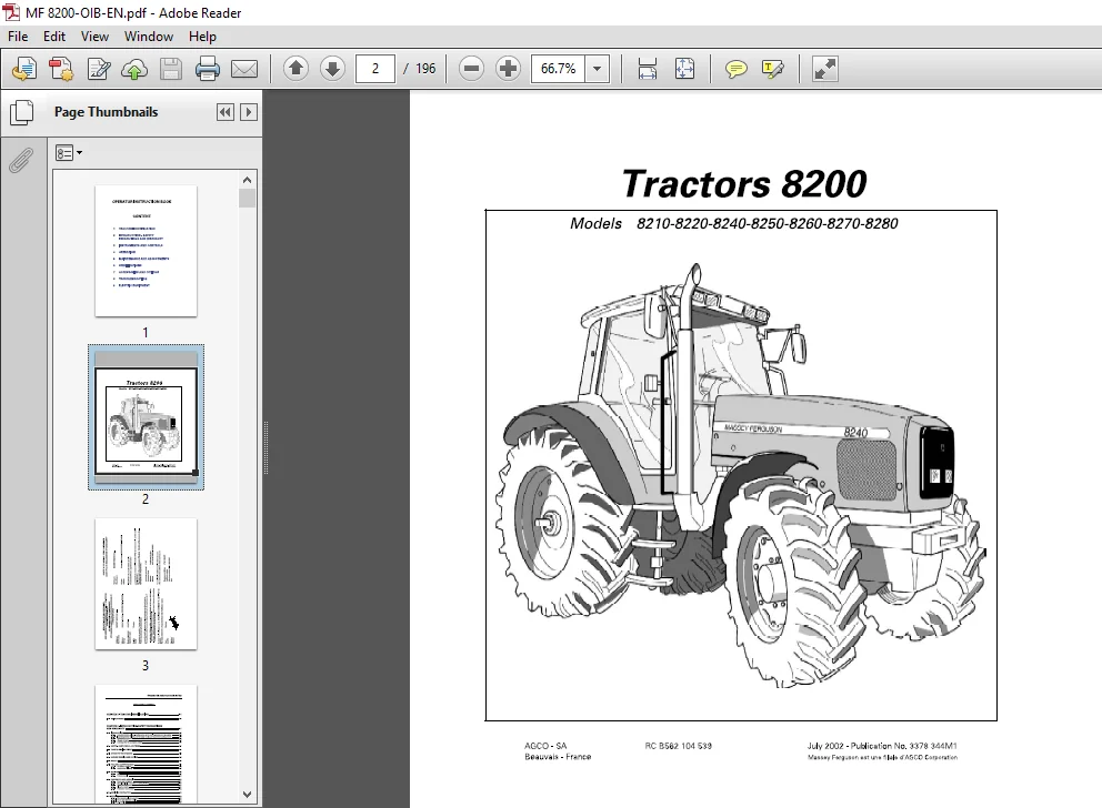
Massey Ferguson EU Tractor 8200 Series 8210 8220 8240 8250 8260 8270 8280 Operator Instruction Manual – PDF DOWNLOAD
DESCRIPTION:
Massey Ferguson EU Tractor 8200 Series 8210 8220 8240 8250 8260 8270 8280 Operator Instruction Manual – PDF DOWNLOAD
INTRODUCTION:
The safety chapter of your User book stresses certain basic safety-related situations which may be encountered during the operation and normal maintenance of the tractor and gives the information needed to cope with these situations. This chapter SUPPLEMENTS any safety instructions given in other chapters of this book. It may be necessary to take additional precautions depending on the equipment used and the working conditions on the site or in the maintenance area. AGCO can under no circumstances exercise direct control over the service entry, operation, inspection, lubrication or maintenance of the tractor. It is therefore YOUR responsibility to take suitable safety measures in such areas. NOTE: This book is published and distributed worldwide and the availability of the equipment indicated, whether on the basic tractor or as accessories, may vary according to the country in which the tractor is used.
- To find out which equipment is available in a given region, contact an AGCO dealer “USE ONLY AGCO attachments and equipment”. The purpose of this book is to allow the owner and the driver to operate the tractor in an appropriate manner. Providing they follow the instructions carefully, the tractor will give them many years of service in the AGCO tradition. Setting the equipment into service at the dealer’s provides the possibility of ensuring that these operating and servicing instructions are properly understood. Always consult the dealer if any part of this book is not understood. It is important for these instructions to be understood and followed. Daily maintenance should become a routine and record of hours in service should be kept. When new parts are required, it is important to use AGCO original spare parts.
- AGCO dealers supply only genuine original parts and can give advice concerning their fitment and use. The use of parts of lower quality may cause serious damage. Customers are advised to only purchase their service parts from an authorized AGCO dealer. Due to the considerable differences in operating conditions, it is not possible for the manufacturer to formulate complete or absolute assertions in its publications concerning the performance or operating methods of its machines or accept liability for any loss or damage which may result from such assertions or possible errors or omissions. To prevent the guarantee being nullified, you should consult your AGCO dealer to obtain special instructions if the tractor is to be used under abnormal conditions which could be detrimental to it (use in deep water or in paddy-fields for instance). These tractors are only designed for usual farming purposes (proper use).
- Any other use is considered as being contrary to the designed use. AGCO declines all liability in cases of physical damage or injuries resulting from improper use the consequences of which shall be borne by the user alone. The conformity and strict adherence to the operating, servicing and repair requirements specified by AGCO are also essential factors for proper use. These tractors must only be used, serviced and repaired by personnel having full knowledge of their specific features and who are aware of the applicable safety rules (prevention of accidents). Customers are strongly recommended to contact an AGCO dealer in the event of after-sale problems and for any adjustments which may be necessary.
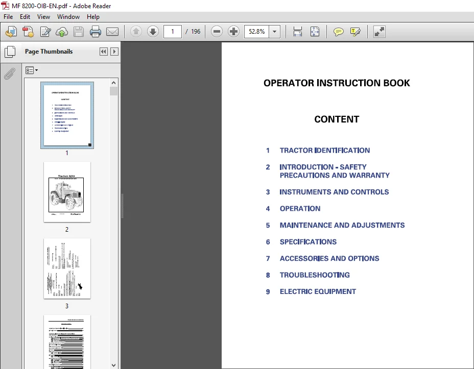
TABLE OF CONTENTS:
Massey Ferguson EU Tractor 8200 Series 8210 8220 8240 8250 8260 8270 8280 Operator Instruction Manual – PDF DOWNLOAD
1 TRACTOR IDENTIFICATION
2 INTRODUCTION – SAFETY
PRECAUTIONS AND WARRANTY
3 INSTRUMENTS AND CONTROLS
4 OPERATION
5 MAINTENANCE AND ADJUSTMENTS
6 SPECIFICATIONS
7 ACCESSORIES AND OPTIONS
8 TROUBLESHOOTING
9 ELECTRIC EQUIPMENT
CHAPTER 1 -TRACTOR IDENTIFICATION 1-1
1 1 – SERIAL NUMBER 1-5
CHAPTER 2 -INTRODUCTION-SAFETY PRECAUTIONS
AND WARRANTY 2-1
2 1 – INTRODUCTION 2-5
2 1 1 – inspection before delivery, service entry on the user’s premises and guarantee 2-5
2 1 2 – Inspection before delivery, service entry on the user’s premises and guarantee 2-6
2 1 3 – Guarantee procedure 2-6
2 1 4 – Change of region 2-6
2 1 5 – Servicing after the guarantee period 2-6
2 2 – SAFETY – ALERT SYMBOL AND TERMS 2-7
2 3 – TRACTOR AND IMPLEMENT 2-7
2 4 – A WORD TO THE OPERATOR 2-8
2 5 – DANGER, WARNING AND CAUTION 2-8
2 6 – DECALS 2-8
2 7 – FOLLOW A SAFETY PROGRAM 2-9
2 7 1 – For proper operation 2-9
2 7 2 – Observe the following 2-9
2 8 – ROPS-CAB 2-9
2 8 1 – Cab 2-9
2 8 2 – Protect yourself 2-10
2 9 – PREPARE FOR SAFE OPERATION 2-10
2 9 1 – Know your equipment 2-10
2 9 2 – Use all available protective and safety devices 2-11
2 9 3 – Check the equipment 2-11
2 9 4 – Clean the tractor 2-12
2 9 5 – Protect the environment 2-12
2 10 – SERVICING THE TRACTOR 2-12
2 11 – STARTING 2-13
2 11 1 – Warn personnel before starting 2-13
2 11 2 – Mount and dismount safely 2-13
2 11 3 – Start safely 2-13
2 11 4 – Follow recommended starting procedures 2-13
2 11 5 – Test the controls 2-13
2 11 6 – Starting fluid 2-13
OPERATOR INSTRUCTION BOOK
2 12 – SAFETY – AFTER OPERATION 2-14
2 12 1 – Make the right moves 2-14
2 12 2 – Follow safe operating practices 2-14
2 12 3 – Watch out for others 2-14
2 12 4 – Risk of overturning 2-15
2 12 5 – To avoid rear overturns 2-15
2 12 6 – To avoid rear overturns 2-16
2 12 7 – General operating hazards 2-17
2 12 8 – Implements and attachments 2-18
2 12 9 – Safety – Towing 2-18
2 12 10 – Road transport 2-19
2 12 11 – Rules of the road 2-19
2 13 – SAFETY – AFTER OPERATION 2-20
CHAPTER 3 -INSTRUMENTS AND CONTROLS 3-1
3 1 – INSTRUMENT PANEL 3-5
3 2 – WARNING LIGHTS PANEL 3-8
3 3 – WARNING LIGHTS PANEL 3-9
3 4 – FIELD FACTS MONITOR 3-10
3 4 1 – Ground Speed Calibration (with radar option) 3-11
3 4 2 – Implement Width Setting 3-11
3 4 3 – Calibration level 1 3-11
3 4 4 – Turbo Boost Calibration (tbc) 3-11
3 4 5 – Transmission Calibration (trnc) 3-12
3 5 – RADAR 3-12
3 6 – PEDALS 3-13
3 7 – RIGHT HAND CONSOLE 3-14
3 8 – LEFT HAND CONSOLE 3-15
3 9 – SEAT 3-16
3 10 – STEERING WHEEL 3-18
3 11 – UPPER CONSOLE 3-18
3 11 1 – Air conditioning operation 3-18
3 12 – SUN VISOR 3-19
3 13 – ROOF HATCH 3-20
3 14 – HIGH VISIBILITY ROOF 3-20
3 15 – OPENING THE HOOD 3-21
CHAPTER 4 -OPERATION 4-1
ii
OPERATOR INSTRUCTION BOOK
4 1 – BREAK IN 4-5
4 1 1 – The following precautions should be taken during the break in period 4-5
4 2- STARTING 4-5
4 2 1 – Starting the engine 4-5
4 3 – STOPPING THE ENGINE 4-6
4 4 – DRIVING THE TRACTOR 4-6
4 4 1 – Foot throttle 4-6
4 4 2 – Choosing the right gear ratio 4-6
4 4 3 – Gear sequence 4-7
4 4 4 – Synchronised range change 4-7
4 4 5 – Power shuttle 4-7
4 5 – “DYNASHIFT” TRANSMISSION 4-7
4 5 1 – General 4-7
4 5 2 – Operation 4-7
4 5 3 – Gear sequence 4-8
4 5 4 – Automation of Dynashift ratio shifting 4-9
4 6 – POWERSHIFT TRANSMISSION 4-10
4 6 1 – General information 4-10
4 6 2 – Selecting direction 4-10
4 6 3 – Selecting gears 4-10
4 6 4 – Starting gears 4-10
4 6 5 – Starting ground travel (Using clutch pedal) 4-11
4 6 6 – Starting ground travel (Without clutch pedal) 4-12
4 6 7 – Direction change without decluching 4-12
4 6 8 – Ground speed matching 4-12
4 6 9 – Transmission clutches matches charges in ground speed not engine speed 4-12
4 6 10 – Allowing the tractor to coast 4-13
4 6 11 – Towing tractor 4-13
4 6 12 – Engine inoperative 4-13
4 6 13 – Engine operative 4-13
4 6 14 – Creeper gearbox 4-13
4 7 – BRAKES 4-14
4 8 – DIFFERENTIAL LOCK 4-14
4 9 – POWER TAKE OFF (PTO) 4-14
4 9 1 – PTO – 540 and 1000 RPM whith interchangeable shaft 4-15
4 9 2 – P T O – 540 and 1000 R PM whith interchangeable end fitting 4-16
4 10 – STEERING 4-16
4 11 – FRONT AXLE 4-17
4 11 1 – Suspended front axle 4-17
4 12- HYDRAULIC LIFT 4-18
4 12 1 – Attaching an implement from the driving seat 4-19
4 12 2 – Attaching an implement using external controls 4-20
4 12 3 – Transport 4-21
4 12 4 – Field operation 4-22
4 13 – AUXILIARY HYDRAULICS 4-23
4 13 1 – Closed center load sensing valves 4-23
4 13 2 – Coupling remote cylinder hoses 4-23
iii
OPERATOR INSTRUCTION BOOK
4 13 3 – Remote outlets 4-23
4 13 4 – Bosch S B23 electrohydraulic spool valves 4-24
4 13 5 – Emergency manual control of the spool valves 4-24
4 13 6 – Memorisation of the joystick (Fig 34) 4-25
4 14 – THREE-POINT LINKAGE 4-26
4 14 1 – Implement installation 4-26
4 14 2 – Lift rods 4-26
4 15 – DRAWBARS AND HITCHES 4-27
4 15 1 – Swinging drawbar 4-27
4 15 2 – Pintle for semi-mounted trailer 4-27
4 16 – ELECTRONIC CONTROL SYSTEM FOR TRANSMISSION CONTROL 4-28
4 16 1 – Differential lock control 4-28
4 16 2 – Power front axle (PFA) 4-28
4 16 3 – Power Take-Off Control 4-28
4 16 4 – lndependant Power Take-Off 4-28
4 16 5 – Dynashift transmission control unit 4-29
4 16 6 – Hydraulic pressure (Low pressure) 4-29
4 16 7 – Economy P T O 4-29
CHAPTER 5 -MAINTENANCE AND ADJUSTMENTS 5-1
5 1 – INITIAL 50 HOUR SERVICE INSPECTION 5-7
5 1 1 – Engine, Fuel and Cooling System 5-7
5 1 2 – Electrical System and Instruments 5-7
5 1 3 – Front Axle and Steering 5-7
5 1 4 – Transmission and Hydraulics 5-7
5 1 5 – Clutches and Brakes 5-7
5 1 6 – General 5-7
5 2 – DEALER SERVICE OPERATION 5-8
5 3 – USER GUIDE 5-10
5 3 1 – Engine, fuel and cooling system 5-10
5 3 2 – Electrical System and Instruments 5-10
5 3 3 – Front Axle and Steering 5-10
5 3 4 – Transmission and Hydraulics 5-10
5 3 5 – General 5-10
5 4 – APPROVED LUBRICANTS 5-11
5 4 1 – Engine oil 5-11
5 4 2 – Recommended SAE viscosity grades (SAE J300d) 5-11
5 4 3 – Engine coolant 5-11
5 4 4 – Transmission 5-11
5 4 5 – Front axle (Dana): API GL5/SAE90 5-11
5 4 6 – Front axle (Carrara): API GL5-85 W/140 5-11
5 4 7 – Rear axle final reduction (sealed): API GL5-85 W/140 5-11
5 4 8 – Lubrication fittings 5-11
5 5 – INSTRUCTIONS FOR PRESSURE WASHING 5-11
5 6 – MAINTENANCE MANUAL 5-12
5 7 – GREASING 5-12
iv
OPERATOR INSTRUCTION BOOK
5 7 1 – Grease the following 5-12
5 8 – ENGINE 5-15
5 8 1 – 6 cylinder engine 8210/8220 5-15
5 8 2 – 6 cylinder engine 8270/8280 5-15
5 8 3 – Check the engine oil level every ten hours or daily 5-16
5 8 4 – Change the engine oil every 300 hours 5-16
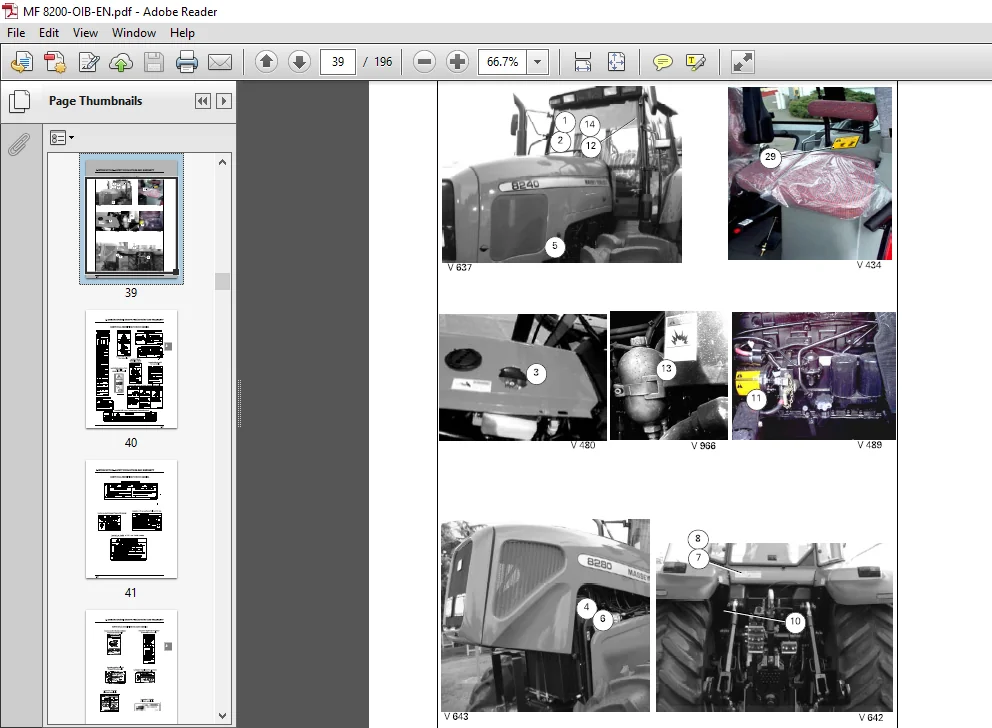
5 8 5 – Change the engine oil filter every 300 hours (7, Fig 7) 5-16
5 8 6 – Closed circuit breather 5-16
5 9 – FUEL SYSTEM 5-17
5 9 1 – Fuel filter (3, Fig 16) 5-17
5 9 2 – Bleeding the fuel system 5-17
5 9 3 – Fuel sediment bowl (4, Fig 16) 5-17
5 9 4 – Fuel tank 5-18
5 9 5 – Fuel injection pump, governor and injectors 5-18
5 10 – AIR CLEANER 5-19
5 10 1 – Main and secondary element 5-19
5 11 – COOLING SYSTEM 5-20
5 11 1 – Expansion tank 8270/80 5-20
5 11 2 – Draining the cooling system 5-20
5 11 3 – Check the fan belt for condition 5-21
5 11 4 – Check the fan belt tension every 300 hours 5-21
5 11 5 – Belt replacement 5-21
5 12 – STEERING, TRANSMISSION AND HYDRAULIC SYSTEM 5-22
5 12 1 – Change the transmission oil every 1200 hours 5-22
5 12 2 – Clean or change the 250 microns suction strainer located inside the center housing
(every 1200 hours): 5-22
5 12 3 – Change the 15 micron transmission oil filter 5-23
5 12 4 – Rear axle final reduction units (sealed compartment) 5-23
5 12 5 – High pressure hydraulic filter 5-23
5 12 6 – Change the 150 micron suction strainer (Fig 27) 5-24
5 12 7 – Transmission oil cooler 5-24
5 13 – AIR CONDITIONING SYSTEM 5-24
5 13 1 – Condenser 5-24
5 13 2 – Checking operation of air conditioning system 5-24
5 13 3 – Cab air filter 5-25
5 13 4 – Compressor belt tension adjustment 5-25
5 14 – FRONT AXLE – 4 WHEEL DRIVE 5-26
5 14 1 – Final reduction units 5-26
5 14 2 – Front axle 5-26
5 15 – SAFETY CAB OR FRAME 5-27
5 16 – CLUTCH AND BRAKES 5-27
5 16 1 – Adjustments 5-27
5 17 – DUAL REAR WHEELS 5-27
5 17 1 – Dual rear wheels 5-27
5 17 2 – Operation 5-27
5 17 3 – Wheel bolts 5-27
5 17 4 – Tyre pressure 5-28
5 17 5 – Tyres pressures 5-28
5 17 6 – Tyre pressure 5-29
V
OPERATOR INSTRUCTION BOOK
5 18 – WHEELS 5-30
5 19 – TRACK ADJUSTMENTS 5-30
5 19 1 – FRONT TRACK 5-30
5 19 2 – Pressed steel wheels 5-31
5 20 – REAR TRACK ADJUSTMENT 5-33
5 20 1 – Settings obtained 5-33
5 20 2 – Changing the position of the wheel on the shaft 5-35
5 20 3 – Changing the position of the wheel on the shaft 5-35
5 21 – ELECTRICAL EQUIPMENT 5-36
5 21 1 – Battery 5-36
5 21 2 – Battery installation 5-37
5 21 3 – Battery removal 5-37
5 21 4 – Alternator 5-37
5 21 5 – Trailer socket 5-38
5 21 6 – Headlights adjustment 5-38
5 22 – FUSE REPLACEMENT 5-39
5 23 – FUSE REPLACEMENT 5-40
5 24 – FUSE REPLACEMENT 5-41
5 25 – FUSE REPLACEMENT 5-42
5 26 – DIESEL FUEL SPECIFICATIONS 5-43
5 27 – FUEL HANDLING AND STORAGE 5-43
5 27 1 – Cleanliness 5-43
5 27 2 – Advice on the use of fuel in cold weather 5-43
5 28 – STORING THE TRACTOR 5-43
CHAPTER 6 – SPECIFICATION S 6- 1
6 1 – ENGINE 6-5
6 1 1 – Fuel system and air cleaner 6-5
6 2 – ROAD SPEEDS 6-6
6 2 1 – Road Speeds at 2200 rev/min – 650/85 R38 tyres – Powershift transmission AG 250 6-6
6 2 2 – Road speeds ” Dynashift” at 2200 rev/min – Heavy duty * with and creeper 1/4 –
20 8R38 tyres 6-7
6 2 3 – Road speeds at 2200 rev/min ” Powersihft” transmission AG 150 –
Heavy duty sealed compartment – 20/8R38 tyres 6-8
6 2 4 – Road speeds at 2200 rev/min ” Powersihft” transmission AG 150 –
Heavy duty sealed compartment – 20/8R38 tyres – With creeper 1/4 6-8
6 2 5 – Road speeds at 2200 rev/min – Heavy duty sealed compartment – 650/85 R38 tyres 6-9
6 2 6 – Road speeds at 2200 rev/min – Heavy duty sealed compartment – 650/85 R38 tires –
With creeper 1/4 6-9
6 3 – ELECTRICAL SYSTEM 6-10
6 4 – COOLING 6-10
vi
OPERATOR INSTRUCTION BOOK
6 5 – TRANSMISSION 6-10
6 6 – FINAL REDUCTION UNITS 6-11
6 7 – POWER TAKE-OFF 6-11
6 8 – FOUR-WHEEL DRIVE FRONT AXLE 6-11
6 9 – HYDRAULICS 6-11
6 9 1 – Closed center hydraulic system with flow and pressure control 6-11
6 10 – HYDRAULIC LIFT 6-12
6 11 – BRAKES 6-12
6 12 – DIFFERENTIAL LOCK – REAR AXLE 6-12
6 13 – STEERING 6-12
6 14 – WHEELS 6-12
6 15 – CAPACITIES 6-13
6 16 – TIGHTENING TORQUE 6-14
6 16 1 – Wheel to rear axle 6-14
6 16 2 – Wheel to front axle 6-14
6 17 – MISCELLANEOUS 6-14
6 18 – NOISE LEVELS 6-14
6 19 – DIMENSIONS AND WEIGHTS 6-15
CHAPTER 7 – ACCES SORIE S AND OPTIONS 7 – 1
7 1 – AVAILABLE ACCESSORIES 7-5
7 2 – TRACTOR PERFORMANCE MONITOR “DATATRONIC 2” 7-6
7 2 1 – I ntroduction 7-6
7 2 2 – Description 7-6
7 2 3 – Symbols 7-7
7 2 4 – Use 7-8
7 2 5 – Use of the memory 7-9
7 2 6 – Use when working 7-10
7 2 7 – Working position 7-11
7 2 8 – Wheel slip control 7-12
7 2 9 – Comparative mode 7-13
7 2 10 – Auxiliary functions 7-14
7 2 11 – Screen contrast 7-14
7 2 12 – Printing of the memory content 7-15
7 3 – REAR DUAL CONTROL 7-16
7 3 1 – General 7-16
7 3 2 – Description of the adjustment screen 7-16
7 3 3 – Settings 7-17
7 3 4 – Use 7-19
7 3 5 – Working operation 7-20
vii
OPERATOR INSTRUCTION BOOK
7 4 – GLOSSARY 7-20
7 5 – FRONT DUAL CONTROL 7-21
7 5 1 – General 7-21
7 5 2 – Description of the adjustment screen 7-21
7 5 3 – Settings 7-21
7 5 4 – Use (Fig 25) 7-22
7 6 – TRAILED IMPLEMENT CONTROL (T I C) 7-23
7 6 1 – General 7-23
7 6 2 – Description of the adjustment screen 7-23
7 6 3 – Settings (Fig 24) 7-23
7 6 4 – Use (Fig 27) 7-24
CHAPTER 8 -TROUBLESHOOTING 8-1
8 1 – TC ERROR CODES 8-5
8 2 – DCC ERROR CODES 8-6
8 3 – LIMP HOME OPERATION 8-7
CHAPTER 9 -ELECTRIC EQUIPMENT 9-1
9 1 – LIGHTTING INSTALLATION (EUROPE) 9-5
9 2 – LIGHTING INSTALLATION (NA) 9-6
9 3 – ENGINE, CAB EQUIPMENT AND ACCESSORIES (EUROPE AND NA) 9-7
IMAGES PREVIEW OF THE MANUAL:
PLEASE NOTE:
- This is the SAME manual used by the dealers to troubleshoot any faults in your vehicle. This can be yours in 2 minutes after the payment is made.
- Contact us at [email protected] should you have any queries before your purchase or that you need any other service / repair / parts operators manual.
S.V