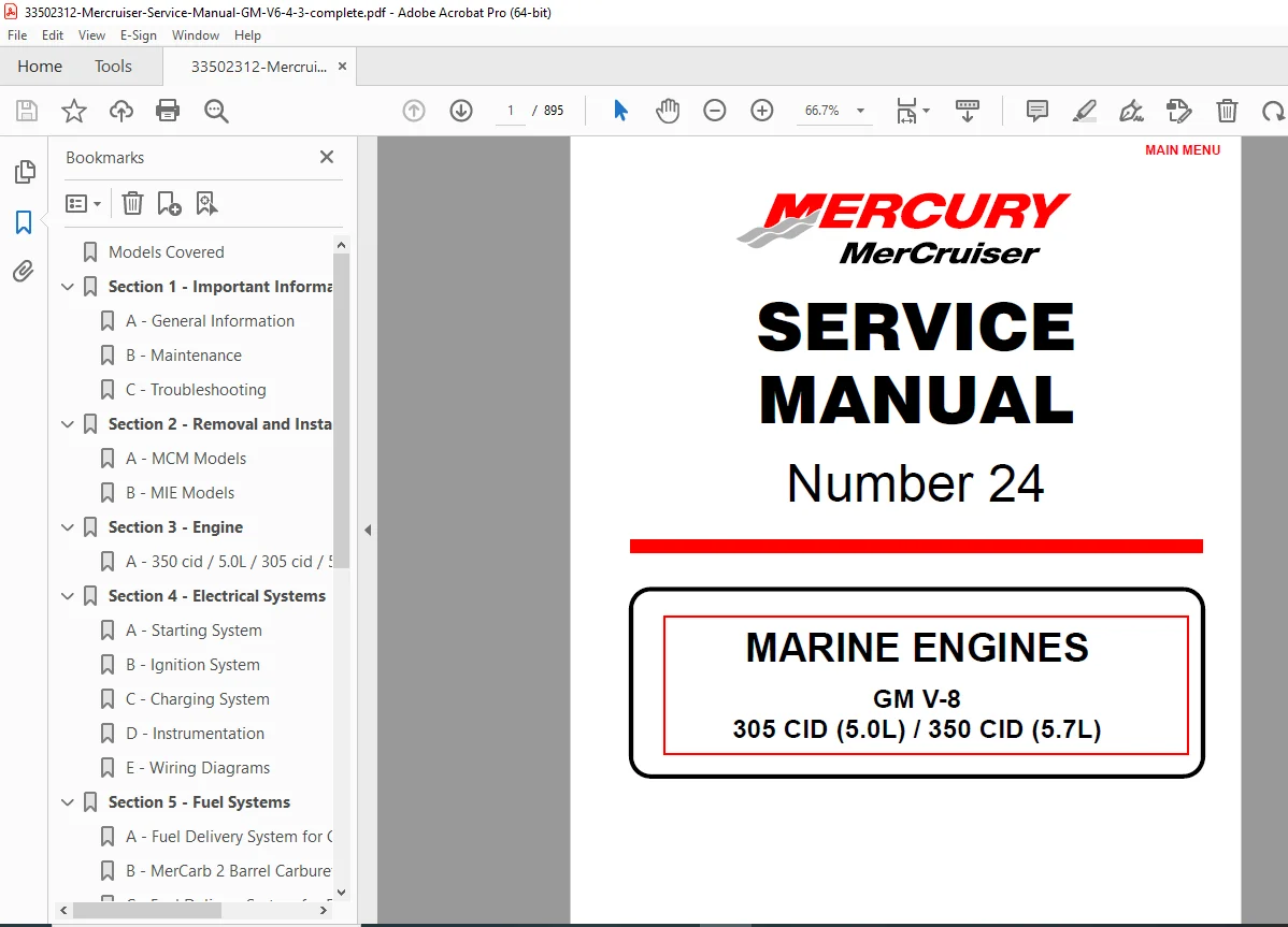
MerCruiser GM V8 5.0L/5.7L Service Manual – PDF DOWNLOAD
Original price was: $110.00.$33.95Current price is: $33.95.
Comprehensive Mercruiser GM V8 5.0L 5.7L service manual from Mercury Marine, covering marine engines troubleshooting, repair, and maintenance for 305 CID and 350 CID models. Includes detailed guides on electrical systems, fuel delivery, cooling, exhaust, drives, and power steering. Ideal for boat owners and mechanics seeking a reliable Mercury Marine engine repair guide 305 350 CID. 895 pages of expert instructions, torque specs, and diagrams
Description
MerCruiser GM V8 5.0L/5.7L Service Manual – PDF DOWNLOAD
Description
This official Mercruiser GM V8 5.0L 5.7L service manual is an essential resource for maintaining and repairing GM V-8 marine engines, specifically the 305 CID (5.0L) and 350 CID (5.7L) models. Published by Mercury Marine in 1999, it provides in-depth coverage of all aspects of engine service, from general information to advanced troubleshooting and component overhauls. As a top Mercury Marine engine repair guide 305 350 CID, it emphasizes safety, proper tools, and step-by-step procedures to ensure reliable performance in sterndrive (MCM) and inboard/ski (MIE) applications.
Key features include detailed sections on MerCruiser sterndrive maintenance handbook topics like engine removal/installation, electrical wiring, fuel systems (carbureted and EFI), cooling systems (seawater and closed), exhaust manifolds, Velvet Drive transmission service instructions, and power steering repairs. It also addresses GM marine engines troubleshooting manual essentials, such as spark plug analysis, oil pressure issues, overheating diagnostics, and ignition timing for Thunderbolt V systems. Whether you’re dealing with poor fuel economy, noisy alternators, or hydraulic valve lifters, this manual offers practical solutions with illustrations, specifications, and exploded views.
The manual is structured for easy navigation, with a clear Service Manual Outline and Table of Contents extracted and categorized below for quick reference. Use it as a complete GM marine engines troubleshooting manual to handle everything from routine maintenance schedules to complex repairs like crankshaft replacement or valve train adjustments.
Extracted Service Manual Outline
- Section 1: Important Information
- A – General Information
- B – Maintenance
- C – Troubleshooting
- Section 2: Removal and Installation
- A – MCM Models
- B – MIE Models
- Section 3: Engine
- A – 350 cid / 5.0L / 305 cid / 5.7L Engines
- Section 4: Electrical Systems
- A – Starting System
- B – Ignition System
- C – Charging System
- D – Instrumentation
- E – Wiring Diagrams
- Section 5: Fuel Systems
- A – Fuel Delivery System For Carbureted Engines
- B – Mercarb® 2 Barrel Carburetor
- C – Fuel Delivery System For Electronic Fuel Injection
- D – Fuel Injection Descriptions And System Operation
- E – Fuel Injection Disassembly And Reassembly
- F – Fuel Injection System Troubleshooting
- G – Diagnostics
- Section 6: Cooling System
- A – Seawater Cooled Models
- B – Closed Cooled Models
- Section 7: Exhaust System
- A – General
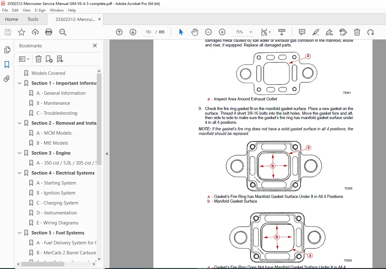
- B – Manifolds, Elbows and Risers
- C – Collectors
- Section 8: Drives
- A – Velvet Drive In-Line and V-Drive Transmission
- B – Velvet Drive 5000 Series Transmission
- C – Hurth Models
- D – Drive Shaft / Propeller Shaft Models
- Section 9: Power Steering System
- A – Pump and Related Components
Extracted Table of Contents (Categorized by Section)
IMPORTANT INFORMATION
- Section 1A – General Information
- Table of Contents → 1A-1
- Introduction → 1A-2
- How to Use This Manual → 1A-2
- Page Numbering → 1A-2
- How to Read a Parts Manual → 1A-3
- Directional References → 1A-4
- Engine Rotation → 1A-4
- Engine Serial Number Locations → 1A-5
- Propeller Information → 1A-5
- Water Testing New Engines → 1A-6
- Boat and Engine Performance → 1A-6
- Boat Bottom → 1A-6
- Marine Fouling → 1A-8
- Weight Distribution → 1A-9
- Water in Boat → 1A-9
- Elevation and Climate → 1A-9
- Section 1B – Maintenance
- Table of Contents → 1B-1
- Tools → 1B-2
- Lubricants / Sealants / Adhesives → 1B-2
- Maintenance Schedules → 1B-3
- Maintenance Intervals → 1B-3
- Engine and Tune-Up Specifications → 1B-7
- Fluid Capacities → 1B-11
- Sterndrive Engines → 1B-11
- Inboard and Ski Engines → 1B-11
- Sterndrives → 1B-11
- Transmission → 1B-12
- 20-Hour Break-In Period → 1B-13
- After Break-in Period → 1B-13
- End of First Season Checkup → 1B-13
- Specifications → 1B-14
- Fuel Recommendations → 1B-14
- Vapor Locking → 1B-14
- Test For Alcohol Content In Gasoline → 1B-16
- Procedure → 1B-16
- Transmission Fluid → 1B-16
- Power Steering Fluid → 1B-16
- Coolant for Closed Cooling System → 1B-16
- Crankcase Oil → 1B-17
- Overfilled Crankcase Oil → 1B-17
- Checking Engine Oil Level / Filling → 1B-18
- Changing Oil and Filter → 1B-18
- Changing Water Separating Fuel Filter → 1B-19
- MCM (Sterndrive) Models → 1B-19
- MIE (Inboard and Ski) Models → 1B-20
- Power Steering System → 1B-21
- Checking Fluid Level → 1B-21
- Engine Warm → 1B-21
- Engine Cold → 1B-21
- Filling and Bleeding → 1B-22
- Checking Fluid Level → 1B-21
- Closed Cooling System → 1B-23
- Checking Coolant Level → 1B-23
- Flushing System MCM (Sterndrive) → 1B-24
- Boat Out of Water → 1B-24
- Boat In Water → 1B-25
- Flushing System MIE (Inboard and Ski) → 1B-26
- Transmission Fluid → 1B-27
- Lubrication → 1B-28
- Throttle Cable → 1B-28
- Shift Cable and Transmission Linkage → 1B-28
- MCM (Sterndrive) Models → 1B-28
- MIE (Inboard and Ski) Models → 1B-29
- Engine Coupler/U-Joint Shaft Splines → 1B-30
- Sterndrive Drive Shaft Extension Models → 1B-31
- Starter Motor → 1B-31
- MIE (Inboard and Ski) Models → 1B-31
- Cleaning Flame Arrestor → 1B-32
- Top Mounted Flame Arrestor → 1B-32
- Black Scorpion Flame Arrestor → 1B-33
- Serpentine Drive Belt → 1B-34
- Component Location → 1B-34
- Inspection → 1B-36
- Replacing and/or Adjusting Tension → 1B-36
- Removal → 1B-36
- Installation and Adjustment → 1B-36
- Ignition Timing → 1B-37
- Thunderbolt V Models → 1B-37
- EFI/MPI Models → 1B-38
- Cold Weather or Extended Storage → 1B-39
- Precautions → 1B-39
- Power Package Layup → 1B-40
- Draining Instructions → 1B-42
- Draining Seawater (Raw-Water) Cooled Models → 1B-42
- Draining Seawater Section of Closed Cooled (Coolant) Models → 1B-48
- Draining Seawater Section of Closed Cooled (Coolant) Models → 1B-50
- Draining Sterndrive → 1B-52
- Recommissioning → 1B-53
- Section 1C – Troubleshooting
- Used Spark Plug Analysis → 1C-2
- Normal Condition → 1C-2
- Chipped Insulator → 1C-2
- Wet Fouling (Oil Deposits) → 1C-3
- Cold Fouling → 1C-3
- Overheating → 1C-3
- High Speed Glazing → 1C-4
- Scavenger Deposits → 1C-4
- Pre-Ignition Damage → 1C-4
- Reversed Coil Polarity → 1C-5
- Splashed Deposits → 1C-5
- Mechanical Damage → 1C-5
- Poor Boat Performance and/or Poor Maneuverability → 1C-6
- Improper Full Throttle Engine RPM → 1C-7
- RPM Too High → 1C-7
- RPM Too Low → 1C-7
- Engine Cranks Over but Will Not Start or Starts Hard → 1C-8
- Important Information → 1C-8
- Testing Thunderbolt V Ignition System → 1C-9
- Fuel System Rich → 1C-10
- Fuel System Lean → 1C-10
- Miscellaneous → 1C-10
- Engine Will Not Crank Over → 1C-11
- Charging System Inoperative → 1C-11
- Noisy Alternator → 1C-12
- Instrumentation Malfunction → 1C-12
- Radio Noise → 1C-12
- Poor Fuel Economy → 1C-13
- Carburetor Malfunctions → 1C-14
- Engine Runs Poorly at Idle → 1C-15
- Engine Runs Poorly At High RPM → 1C-16
- Engine Acceleration Is Poor → 1C-17
- Troubleshooting with Vacuum Gauge → 1C-17
- Engine Noise → 1C-18
- Important Information → 1C-18
- Valve Cover Area → 1C-18
- Cylinder Area → 1C-19
- Camshaft Area → 1C-19
- Crankshaft Area → 1C-20
- Miscellaneous → 1C-21
- Oil Pressure → 1C-22
- Low Oil Pressure → 1C-23
- High Oil Pressure → 1C-23
- Excessive Oil Consumption → 1C-24
- Water In Engine → 1C-25
- Important Information → 1C-25
- Water on Top of Pistons → 1C-26
- Water in Crankcase Oil → 1C-26
- Engine Overheats (Mechanical) → 1C-27
- Engine Overheats (Cooling System) → 1C-28
- Insufficient Water Flow from Belt Driven Seawater Pickup Pump → 1C-29
- Power Steering → 1C-30
- Poor, Erratic, or No Assist → 1C-30
- Noisy Pump → 1C-31
- Fluid Leaks → 1C-31
- Troubleshooting Silent Choice Exhaust Silencer System → 1C-32
- Compressor Will Not Run – Testing Mode Switch → 1C-33
- Compressor Will Not Run – Testing Air Pump → 1C-33
- Air Pump Runs – System Inoperative → 1C-33
- Used Spark Plug Analysis → 1C-2
REMOVAL AND INSTALLATION
- Section 2A – MCM Models
- Torque Specifications → 2A-2
- Tools → 2A-2
- Lubricants / Sealants / Adhesives → 2A-2
- Preparation → 2A-3
- Removal → 2A-3
- Installation → 2A-5
- Drive Shaft Extension Models → 2A-7
- Engine Mount Adjustment Was Not Disturbed During Service → 2A-7
- Engine Mount Adjustment Was Disturbed During Service → 2A-10
- Alignment → 2A-15
- Water Hose Connections → 2A-17
- Electrical Connections → 2A-18
- Fuel Supply Connections → 2A-20
- Throttle Cable Installation and Adjustment → 2A-21
- Power Steering Connections → 2A-23
- Exhaust Hose Connections → 2A-24
- Section 2B – MIE Models
- Identification → 2B-2
- Velvet Drive In-Line and V-Drive Transmissions → 2B-2
- Velvet Drive Down-Angle Transmission → 2B-2
- Hurth Transmissions → 2B-3
- Torque Specifications → 2B-3
- Lubricants / Sealants / Adhesives → 2B-4
- Preparation → 2B-4
- Removal → 2B-4
- Installation and Alignment → 2B-6
- Engine Final Alignment → 2B-7
- Engine Connections → 2B-10
- Attaching / Adjusting Reversed Attachment Morse Shift Cables → 2B-22
- Identification → 2B-2
ENGINE
- Section 3A – 350 cid / 5.0L / 305 cid / 5.7L Engines
- Torque Specifications → 3A-3
- Tools → 3A-5
- Lubricants / Sealants / Adhesives → 3A-6
- Specifications → 3A-7
- General Specifications → 3A-7
- Engine Specifications → 3A-8
- General Information → 3A-12
- Repair Procedures → 3A-12
- Engine Identification → 3A-12
- Engine Rotation → 3A-13
- Description → 3A-13
- Crankshaft → 3A-13
- Piston and Connecting Rods → 3A-13
- Camshaft and Drive → 3A-13
- Cylinder Head → 3A-14
- Valve Train → 3A-14
- Intake Manifold → 3A-14
- Lubrication System → 3A-14
- Bearing Failures → 3A-15
- Piston Failures → 3A-17
- Pre-Ignition → 3A-17
- Detonation → 3A-18
- Engine Mounts → 3A-19
- Rocker Arm Cover → 3A-21
- Removal → 3A-21
- Installation → 3A-21
- Intake Manifold → 3A-22
- Removal → 3A-22
- Cleaning and Inspection → 3A-22
- Installation → 3A-23
- Rocker Arm / Push Rod → 3A-24
- Removal → 3A-24
- Cleaning and Inspection → 3A-24
- Installation → 3A-24
- Valve Adjustment → 3A-25
- Engine Stopped → 3A-25
- Engine Operating → 3A-26
- Hydraulic Valve Lifters → 3A-27
- Locating Noisy Lifters → 3A-27
- Removal → 3A-28
- Cleaning and Inspection → 3A-29
- Installation → 3A-29
- Valve Stem Oil Seal / Valve Spring → 3A-30
- Removal – Head Installed → 3A-30
- Valve Assembly (Exploded View) → 3A-31
- Installation – Head Installed → 3A-31
- Cylinder Head → 3A-32
- Removal → 3A-32
- Cleaning and Inspection → 3A-32
- Installation → 3A-33
- Cylinder Head and Valve Conditioning → 3A-34
- Disassembly → 3A-34
- Valve Guide Bore Repair → 3A-37
- Valve Springs – Checking Tension → 3A-37
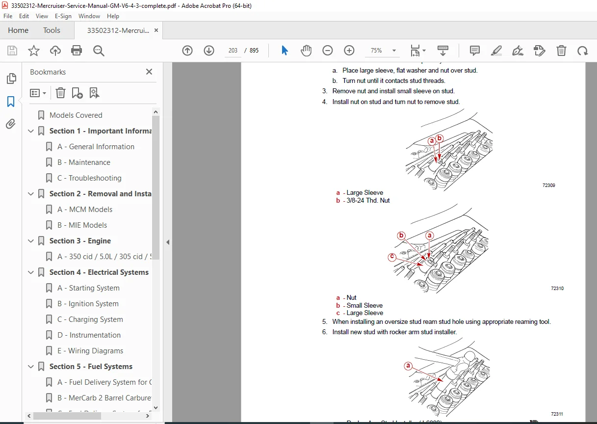
- Rocker Arm Stud Replacement → 3A-38
- Valve Seat Repair → 3A-39
- Valve Grinding → 3A-40
- Reassembly → 3A-40
- Crankcase Oil Dipstick Specifications → 3A-43
- All Engines → 3A-43
- Oil Pan → 3A-45
- Removal → 3A-45
- Cleaning and Inspection → 3A-45
- Installation → 3A-45
- Oil Pump → 3A-48
- Exploded View → 3A-48
- Removal → 3A-49
- Disassembly → 3A-49
- Cleaning and Inspection → 3A-49
- Reassembly → 3A-50
- Installation → 3A-50
- Torsional Damper → 3A-51
- Installation → 3A-51
- Crankcase Front Cover/Oil Seal → 3A-53
- Oil Seal Replacement (Without Removing Front Cover) → 3A-53
- Crankcase Front Cover → 3A-54
- Removal → 3A-54
- Cleaning and Inspection → 3A-54
- Installation → 3A-54
- Flywheel → 3A-56
- Removal → 3A-56
- Cleaning and Inspection → 3A-57
- Installation → 3A-57
- Rear Main Oil Seal → 3A-58
- Removal → 3A-58
- Cleaning and Inspection → 3A-59
- Installation → 3A-59
- Rear Main Oil Seal Retainer → 3A-60
- Removal → 3A-60
- Cleaning and Inspection → 3A-60
- Installation → 3A-60
- Main Bearings → 3A-61
- Inspection → 3A-61
- Checking Clearances → 3A-61
- Replacement → 3A-62
- Connecting Rod Bearings → 3A-65
- Inspection and Replacement → 3A-65
- Connecting Rod / Piston Assembly → 3A-67
- Removal → 3A-67
- Disassembly → 3A-68
- Cleaning and Inspection → 3A-68
- Reassembly → 3A-70
- Installation → 3A-72
- Crankshaft → 3A-74
- Removal → 3A-74
- Cleaning and Inspection → 3A-76
- Installation → 3A-77
(Note: The manual continues with additional sections on Electrical Systems, Fuel Systems, Cooling System, Exhaust System, Drives, and Power Steering System, as outlined earlier. Remaining pages cover detailed procedures like Thunderbolt V ignition system repair and Velvet Drive transmission service instructions.)
This Mercruiser GM V8 5.0L 5.7L service manual is perfect for DIY enthusiasts or professionals needing a thorough MerCruiser sterndrive maintenance handbook, ensuring safe and effective repairs on these classic marine powerplants.
Short File Details
- Manual Name: MerCruiser Service Manual #24 GM V-8 305 CID (5.0L) / 350 CID (5.7L)
- Models Covered: GM V-8 Marine Engines – 305 CID (5.0L), 350 CID (5.7L); MCM (Sterndrive) and MIE (Inboard/Ski) models
- Year: 1999
- Manual PDF Quality: High (clear text, diagrams, and formatting)
- No of Pages: 895