Mercury Mariner 135HP 150HP 175HP 200HP Outboards Service Manual – PDF DOWNLOAD
Original price was: $45.95.$22.95Current price is: $22.95.
Mercury Mariner 135HP 150HP 175HP 200HP Outboards Service Manual
Description
Mercury Mariner 135HP 150HP 175HP 200HP Outboards Service Manual
FILE DETAILS:
Mercury Mariner 135HP 150HP 175HP 200HP Outboards Service Manual
Language : English
Pages : 638
Downloadable : YES
Format : PDF
Size : 15.9 MB
DESCRIPTION:
Mercury Mariner 135HP 150HP 175HP 200HP Outboards Service Manual
Users of This Manual:
This service manual has been written and published by the Service Department of Mercury Marine to aid our dealers’ mechanics and company service personnel when servicing the products described herein. It is assumed that these personnel are familiar with the servicing procedures of these products, or like or similar products manufactured and marketed by Mercury Marine, that they have been trained in the recommended servicing procedures of these products which includes the use of mechanics’ common hand tools and the special Mercury Marine or recommended tools from other suppliers.
- We could not possibly know of and advise the service trade of all conceivable procedures by which a service might be performed and of the possible hazards and/or results of each method. We have not undertaken any such wide evaluation. Therefore, anyone who uses a service procedure and/or tool, which is not recommended by the manufacturer, first must completely satisfy himself that neither his nor the products safety will be endangered by the service procedure selected.
- All information, illustrations and specifications contained in this manual are based on the latest product information available at the time of publication. As required, revisions to this manual will be sent to all dealers contracted by us to sell and/or service these products. It should be kept in mind, while working on the product, that the electrical system and ignition system are capable of violent and damaging short circuits or severe electrical shocks.
- When performing any work where electrical terminals could possibly be grounded or touched by the mechanic, the battery cables should be disconnected at the battery. Any time the intake or exhaust openings are exposed during service they should be covered to protect against accidental entrance of foreign material which could enter the cylinders and cause extensive internal damage when the engine is started.
TABLE OF CONTENTS:
Mercury Mariner 135HP 150HP 175HP 200HP Outboards Service Manual
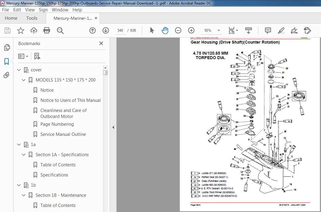
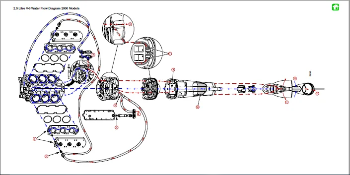
cover.................................................................................................  1
	MODELS 135 * 150 * 175 * 200......................................................................  1
		Notice........................................................................................  2
		Notice to Users of This Manual................................................................  2
		Cleanliness and Care of Outboard Motor........................................................  3
		Page Numbering................................................................................  3
		Service Manual Outline........................................................................  4
1a....................................................................................................  5
	Section 1A - Specifications.......................................................................  5
		Table of Contents.............................................................................  5
		Specifications................................................................................  5
1b.................................................................................................... 10
	Section 1B - Maintenance.......................................................................... 10
		Table of Contents............................................................................. 10
		Specifications................................................................................ 10
		Special Tools................................................................................. 11
		Quicksilver Lubricant/Sealant................................................................. 11
		Inspection and Maintenance Schedule........................................................... 13
			Before Each Use........................................................................... 13
			After Each Use............................................................................ 13
			Every 100 Hours of Use or Once Yearly, Whichever Occurs First............................. 13
		Flushing Engine............................................................................... 14
			Flushing Cooling System – Using Cowl Flush Plug........................................... 14
			Flushing Cooling System – Using Flushing Attachment 44357A2............................... 14
		Fuel System................................................................................... 15
			Fuel Line Inspection...................................................................... 15
			Fuel Line Filter (Models With Carburetors)................................................ 15
			Water Separating Fuel Filter – EFI Models................................................. 16
		Corrosion Control Anode....................................................................... 16
		Spark Plug Inspection......................................................................... 17
		Battery Inspection............................................................................ 17
		Fuse Replacement.............................................................................. 18
		Lubrication Points............................................................................ 18
		Checking Power Trim Fluid..................................................................... 20
		Gear Case Lubrication......................................................................... 21
		Storage Preparation........................................................................... 22
1c.................................................................................................... 25
	Section 1C - General Information.................................................................. 25
		Table of Contents............................................................................. 25
		Serial Number Location........................................................................ 25
		Conditions Affecting Performance.............................................................. 26
			Weather................................................................................... 26
			Boat...................................................................................... 27
			Trim...................................................................................... 28
			Engine.................................................................................... 29
			Engine Compression........................................................................ 29
		Following Complete Submersion................................................................. 30
		Model 135/150/200 Powerhead Front View........................................................ 32
		Model 135/150/200 Powerhead Starboard View.................................................... 33
		Model 135/150/200 Powerhead Port View......................................................... 34
		Model 135/150/200 Powerhead Top View.......................................................... 35
		Model 135/150/200 Powerhead Aft View.......................................................... 36
		Model 150 XRI/175 XRI/200 XRI Powerhead Front View............................................ 37
		Model 150 XRI/175 XRI/200 XRI Powerhead Starboard View........................................ 38
		Model 150 XRI/175 XRI/200 XRI Powerhead Port View............................................. 39
		Model 150 XRI/175 XRI/200 XRI Powerhead Top View.............................................. 40
		Model 150 XRI/175 XRI/200 XRI Powerhead Aft View.............................................. 41
		Painting Procedures........................................................................... 42
		Decal Application............................................................................. 43
1d.................................................................................................... 45
	Section 1D - Outboard Motor Installation.......................................................... 45
		Table of Contents............................................................................. 45
		Installation Specifications................................................................... 45
		Lifting Outboard.............................................................................. 45
		Installing Outboard to Boat Transom........................................................... 46
		Installing Outboard........................................................................... 47
			Drilling Outboard Mounting Holes.......................................................... 47
			Securing Outboard To Boat Transom......................................................... 48
		Steering Cable................................................................................ 48
		Steering Link Rod............................................................................. 49
		Electrical, Hoses and Control Cables.......................................................... 50
			Installation Note......................................................................... 50
			Remote Wiring Harness..................................................................... 50
			Battery Cables............................................................................ 51
			Fuel Hose Connection...................................................................... 52
			Oil Hose Connections...................................................................... 52
			Speedometer Tubing Connection............................................................. 52
			Water Pressure Tubing Connection.......................................................... 52
		Shift Cable................................................................................... 53
			Installation.............................................................................. 54
		Throttle Cable................................................................................ 56
			Front Clamp Reassembly.................................................................... 57
		Filling the Oil Injection System.............................................................. 58
		Bleeding Air from Oil Injection Pump and Oil Injection Outlet Hose............................ 59
		Adjusting the Oil Injection Pump.............................................................. 59
		Trim In Stop Adjustment....................................................................... 60
		Trim Tab Adjustment........................................................................... 60
			Models Without Power Steering............................................................. 60
			Models With Power Steering................................................................ 61
2a.................................................................................................... 63
	Section 2A - Ignition............................................................................. 63
		Table of Contents............................................................................. 63
		Specifications................................................................................ 64
		Special Tools................................................................................. 66
		Flywheel/Starter Motor........................................................................ 68
		CDM Mounting.................................................................................. 70
		Solenoid Mounting............................................................................. 72
		Theory of Operation........................................................................... 74
		V-6 2.0/2.5L CDM Ignition..................................................................... 75
			Capacitor Charging #1, #2, & #3 CDMs...................................................... 76
			Capacitor Charging #4, #5 & #6 CDMs....................................................... 76
			#1 CylinderTrigger Circuit................................................................ 76
			Ignition Coil Circuit..................................................................... 76
			Stop Circuit.............................................................................. 76
		Ignition Component Description................................................................ 77
			Capacitor Discharge Module (CDM).......................................................... 77
			Trigger Coil.............................................................................. 77
			Control Module............................................................................ 77
			Stator Assembly........................................................................... 78
			Flywheel.................................................................................. 78
		CDM (P/N 827509) Trouble Shooting Flowchart................................................... 79
			CDM (P/N 827509).......................................................................... 79
			CDM Stop Diode Trouble Shooting........................................................... 80
			CDM Trouble Shooting Flowchart............................................................ 82
			Direct Voltage Adaptor (DVA).............................................................. 87
			Troubleshooting Tips...................................................................... 87
		Ignition Test Procedures...................................................................... 88
			Direct Voltage Adaptor (DVA) Test......................................................... 88
			Resistance Tests.......................................................................... 92
		Bias Circuit.................................................................................. 92
		Shift Stabilizer Circuit...................................................................... 93
		Idle Stabilizer............................................................................... 93
		Rev-Limit Circuit............................................................................. 93
		EFI Injector Timing Signal Test............................................................... 94
		EFI Detonation Control System................................................................. 94
		Ignition Component Removal.................................................................... 95
			Flywheel Removal.......................................................................... 95
			Flywheel Installation..................................................................... 95
			Stator Removal............................................................................ 96
			Stator Installation....................................................................... 97
			Trigger Removal........................................................................... 98
			Trigger Installation...................................................................... 99
			CDM Removal...............................................................................100
			CDM Installation..........................................................................100
			Control Module Removal....................................................................100
			Control Module Installation...............................................................100
			Detonation Module Removal (200 XRI only)..................................................101
			Detonation Module Installation............................................................101
2b....................................................................................................102
	Section 2B - Charging and Starting System.........................................................102
		Table of Contents.............................................................................102
		Specifications................................................................................102
		Electrical Plate..............................................................................103
		Flywheel/Starter Motor........................................................................105
		Starter Motor.................................................................................107
		Battery Cable Size............................................................................108
		Replacement Parts.............................................................................108
		Recommended Battery...........................................................................108
		Special Tools.................................................................................109
		Battery.......................................................................................109
		Charging a Discharged Battery.................................................................110
		Winter Storage of Batteries...................................................................110
		Flywheel Removal and Installation.............................................................111
			Removal...................................................................................111
			Installation..............................................................................112
		Battery Charging System Description...........................................................113
			Precautions...............................................................................113
		Battery Charging System Troubleshooting.......................................................114
			General Troubleshooting...................................................................114
			40 Ampere Alternator System...............................................................114
			Troubleshooting 40 Amp Alternator System..................................................115
			Removal of Voltage Regulators.............................................................117
			Installation of Voltage Regulators........................................................118
			Incorporating a Battery Isolator with a 40 Ampere Charging System.........................118
			System Wired for 40 Ampere Output to Isolator.............................................118
			System Wired for Split Output.............................................................119
		Starter System................................................................................119
			Starter System Components.................................................................119
			Description...............................................................................119
			Troubleshooting the Starter Circuit.......................................................120
			Starter Circuit Troubleshooting Flow Chart................................................121
			Starter Removal...........................................................................122
			Installation..............................................................................123
			Disassembly...............................................................................123
			Starter Cleaning, Inspection and Testing..................................................125
			Starter Reassembly........................................................................128
2c....................................................................................................133
	Section 2C - Timing, Synchronizing & Adjusting....................................................133
		Table of Contents.............................................................................133
		Specifications................................................................................133
		Special Tools.................................................................................135
		Adjustments...................................................................................136
			Carburetor Models.........................................................................136
			Electronic Fuel Injection Models..........................................................142
2d....................................................................................................153
	Section 2D - Wiring Diagrams......................................................................153
		Table of Contents.............................................................................153
		Power Trim Wiring Diagram.....................................................................154
		Instrument Wiring Connections.................................................................155
		Commander 3000 Classic Panel Remote Control...................................................156
		Commander 3000 Panel Remote Control...........................................................157
		Instrument/Lanyard Stop Switch Wiring Diagram.................................................158
		Oil Level Gauge Wiring Diagram................................................................159
		Instrument/Lanyard Stop Switch Wiring Diagram (Dual Outboard).................................160
		Panel Mount Remote Control Wiring Installation................................................162
		QSI Gauge Wiring Diagrams.....................................................................163
			Tachometer Wiring Diagram.................................................................163
			Water Temperature Gauge...................................................................164
			Oil Level Gauge Wiring....................................................................165
			Engine Synchronizer Wiring Diagram........................................................167
		Maintenance...................................................................................168
		Multi-Function Gauge..........................................................................169
			Dip Switch Setting/Testing................................................................169
			Outboard Multi-Function Gauge Setting.....................................................170
		2.5 Litre V-6 Carburetor Wiring Diagram 2000 Models...........................................171
		2.5 Litre V-6 150/175 EFI Wiring Diagram 2000 Models..........................................172
		2.5 Litre V-6 200 EFI Wiring Diagram 2000 Models..............................................173
3a....................................................................................................174
	Section 3A - Fuel Pump............................................................................174
		Table of Contents.............................................................................174
		Specifications................................................................................175
		Special Tools.................................................................................175
		Fuel Pump Assembly............................................................................177
		Fuel Pump Description/Operation...............................................................179
		Checking for Restricted Fuel Flow Caused by Anti-Siphon Valves................................179
		Checking Fuel Pump Lift (Vacuum)..............................................................180
			Vacuum Test Troubleshooting...............................................................180
			Testing Fuel Pump.........................................................................181
			Fuel Pump Removal/Disassembly.............................................................182
			Cleaning/Inspection.......................................................................183
			Reassembly/lnstallation...................................................................183
3b....................................................................................................186
	Section 3B - Carburetors..........................................................................186
		Table of Contents.............................................................................186
		Attenuator And Carb Throttle Levers...........................................................187
		Fuel Lines....................................................................................189
		Carburetor....................................................................................191
		Fuel System - Troubleshooting.................................................................195
		Reed Valve Leak Test..........................................................................197
		Thermal Air Valve Circuit Description.........................................................198
		Enrichener System Description.................................................................199
			Manual Operation of Enrichener Valve......................................................199
			Enrichener Valve Test.....................................................................200
		Carburetor....................................................................................201
		Carburetor Fuel Circuits......................................................................202
			Float Bowl Circuit........................................................................202
			Idle Circuit..............................................................................203
			Cold Start Circuit........................................................................204
			Off-Idle Circuit..........................................................................204
			Main Circuit..............................................................................205
			Back Draft Circuit........................................................................206
			Carburetor Specifications.................................................................207
			Carburetor Placement and Jet Location for Each Cylinder...................................208
			Carburetor Jet Placement..................................................................209
			High Altitude Recommendations.............................................................210
			Jet Part Number Chart.....................................................................210
			High Altitude Jet Chart...................................................................211
		Removing Carburetor(s) from Engine............................................................212
			Throttle Shaft Screws.....................................................................213
			Float Adjustment..........................................................................213
			Installing Carburetor(s) to Engine........................................................214
3c....................................................................................................215
	Section 3C - Fuel Injection.......................................................................215
		Table of Contents.............................................................................215
		Specifications................................................................................216
		Special Tools.................................................................................217
		Ignition Controller and Detonation Module.....................................................220
		ECM Assembly..................................................................................222
		Fuel Management System........................................................................224
		Fuel Pump.....................................................................................228
		Electronic Fuel Injection (EFl) System........................................................230
			Introduction..............................................................................230
			Using the Test Procedures.................................................................230
			EFI System Tests..........................................................................230
			Safety Precautions........................................................................230
			Fuel Injection System Function............................................................231
		Preliminary Checks............................................................................231
			Ignition Spark Check......................................................................231
			Electronic Fuel Injection Set Up..........................................................232
			Fresh Quality Fuel........................................................................232
			Low Battery Voltage.......................................................................232
		Fuel Flow Diagram.............................................................................233
		Fuel Flow Component Description...............................................................234
			Pulse Fuel Pump (k).......................................................................234
			Water Separating Filter (i)...............................................................234
			Vapor Separator (n).......................................................................234
			Bleed System (f,g)........................................................................234
			Final Filter (t)..........................................................................234
			Electric Fuel Pump (Inside Vapor Separator) (q)...........................................234
			Fuel Injectors (a)........................................................................235
			Induction Manifold (r)....................................................................235
			Fuel Pressure Regulator (e)...............................................................235
			EFI Electrical Components.................................................................235
		EFI Fuel Management (Low Pressure Fuel Route).................................................238
		EFI Fuel Management (High Pressure Fuel Route)................................................239
		Fuel Rail Electrical/Fuel Determination.......................................................240
		EFI System Test Procedures....................................................................241
			Fuel Gauge Connection/Pressure Test.......................................................241
			Vapor Separator Fuel Delivery Test........................................................242
			Vapor Separator Float Test................................................................243
			Water Separating Filter Flow Test.........................................................244
			Pulse Fuel Pump Delivery Test.............................................................245
			Final Filter Check and De-Pressurizing EFI System Procedures..............................246
			Pressure Regulator Test...................................................................248
			Electric Fuel Pump Voltage Test...........................................................250
			Injector Electrical Harness Test..........................................................253
			ECM Injector Driver Test..................................................................254
			Injector Fuel Delivery Test...............................................................254
			Injector Operation Test (Manifold Cover Removed)..........................................254
			Induction Manifold Leak Check (Manifold Cover Removed)....................................257
			Air Temperature Sensor Test...............................................................259
			Engine Head Temperature Sensor Test.......................................................260
			Detonation Control System Test (200 Models Only)..........................................260
			Detonation Sensor Check...................................................................261
			Detonation Control Module Check...........................................................262
			Throttle Position Sensor Test.............................................................263
			Map Sensor Test...........................................................................264
			Problem Diagnosis.........................................................................265
		Engine Head Temperature Sensor Removal........................................................268
		EFI Induction Manifold Removal................................................................269
			Water Separating Filter Assembly Removal..................................................270
			Water Separating Filter Assembly Installation.............................................271
			Throttle Position Sensor and Temperature Sensor Fuel Injector Harness Disconnections......271
			Oil Reservoir Removal.....................................................................273
			Fuel Pressure Regulator Removal...........................................................274
			Fuel Pressure Regulator Disassembly.......................................................275
			Fuel Pressure Regulator Reassembly........................................................275
			Vapor Separator Removal...................................................................276
			Vapor Separator Disassembly...............................................................278
			Installing Vapor Separator Assembly to Induction Manifold.................................284
			Manifold Removal..........................................................................287
		EFI Induction Manifold Disassembly............................................................289
			Air Temperature Sensor Removal............................................................289
			Throttle Position Sensor Removal..........................................................290
			Fuel Rail Removal.........................................................................291
			Fuel Rail Disassembly.....................................................................293
			Fuel Injector Removal and Disassembly.....................................................293
			Injector Harness Removal..................................................................295
			Throttle Linkage Removed..................................................................296
		EFI System Cleaning and Inspection............................................................297
		Induction Manifold Assembly...................................................................298
			Injector Harness Installation.............................................................298
			Fuel Injector Assembly and Installation...................................................299
			Fuel Rail Assembly........................................................................301
			Fuel Rail Installation....................................................................301
			Throttle Position Sensor Installation.....................................................303
			Air Temperature Sensor Installation.......................................................304
		EFI Induction Manifold Installation...........................................................306
			Oil Reservoir Installation................................................................308
			Vapor Separator Installation..............................................................309
			Throttle Position Sensor, Air Temperature Sensor and Fuel Injector Harness Connections....311
			ECM Installation..........................................................................313
			Engine Head Temperature Sensor Installation...............................................314
3d....................................................................................................315
	Section 3D - Oil Injection........................................................................315
		Table of Contents.............................................................................315
		Operation of the Oil Injection System.........................................................316
			Final Checks Before Operation of Engine...................................................316
			Checking Operation of the Oil Injection System (Engine Running)...........................317
		Oil Injection Components......................................................................318
		Oil Injection Flow System.....................................................................321
		Pump Drive Assembly...........................................................................322
		Pump Drive System.............................................................................322
			Set Up Instructions for Oil Injection System..............................................323
			Bleeding Air from Oil Injection Pump and Oil Injection Outlet Hose........................325
			Adjusting Oil Injection Pump..............................................................326
		Oil Injection Pump............................................................................327
		Worm Bushing..................................................................................328
			Worm Bushing Removal......................................................................328
			Worm Bushing Installation.................................................................328
			Oil Injection Pump Installation...........................................................329
			Installing Drive Gear (for Oil Injection Pump) onto Crankshaft............................329
			Oil Injection System Trouble Shooting Chart...............................................330
		Oil Pump Volume (Flow) Test...................................................................332
			Engine Mounted Oil Reservoir..............................................................333
3e....................................................................................................334
	Section 3E – Emissions............................................................................334
		Table of Contents.............................................................................334
		Exhaust Emissions Standards...................................................................334
			What Are Emissions?.......................................................................334
			Hydrocarbons – HC.........................................................................334
			Carbon Monoxide – CO......................................................................334
			Oxides of Nitrogen - NOx..................................................................335
			Controlling Emissions.....................................................................335
			Stoichiometric (14.7:1) Air/Fuel Ratio....................................................335
		Outboard Hydrocarbon Emissions Reductions.....................................................335
		Stratified vs Homogenized Charge..............................................................336
			Homogenized Charge........................................................................336
			Stratified Charge.........................................................................337
		Emissions Information.........................................................................337
			Manufacturer s Responsibility:............................................................337
			Dealer Responsibility:....................................................................338
			Owner Responsibility:.....................................................................338
			EPA Emission Regulations:.................................................................338
		Manufacturer s Certification Label:...........................................................339
		Service Replacement Certification Label.......................................................340
			Removal...................................................................................340
			Date Code Identification..................................................................340
			Installation..............................................................................340
			Decal Location:...........................................................................340
4a....................................................................................................341
	Section 4A - Powerhead............................................................................341
		Table of Contents.............................................................................341
		Powerhead Specifications (2 Liter Model 135)..................................................342
		Powerhead Specifications (2.5 Liter Model 150/175/200)........................................343
		Special Tools.................................................................................344
			Powerhead Repair Stand....................................................................345
		Cylinder Block Assembly.......................................................................346
		Exhaust Manifold and Exhaust Plate............................................................348
		Crankshaft, Pistons and Connecting Rods.......................................................350
		Reed Block and Cylinder Head..................................................................352
		Bleed System Routing (Carburetor Models)......................................................354
		Bleed System Routing (EFI Models).............................................................355
		Torque Sequence...............................................................................356
		General Information...........................................................................357
		Powerhead Removal from Driveshaft Housing.....................................................358
			Removing Engine Components................................................................362
		Powerhead Disassembly.........................................................................363
		Cleaning and Inspection.......................................................................374
			Cylinder Block and Crankcase Cover........................................................374
			Special Service Information...............................................................374
			Cylinder Bores............................................................................375
			Pistons and Piston Rings..................................................................376
			Cylinder Heads and Exhaust Divider Plate..................................................378
			Crankshaft................................................................................378
			Crankshaft (and End Cap) Bearings.........................................................379
			Reed Block Assembly.......................................................................379
			Reed Block Housing........................................................................380
			Connecting Rods...........................................................................380
		Powerhead Reassembly and Installation.........................................................383
			General...................................................................................383
			Crankshaft Installation...................................................................388
			Piston and Connecting Rod Reassembly......................................................390
			Piston and Piston Ring Combinations.......................................................393
			Piston Installation.......................................................................393
			Crankcase Cover Installation..............................................................397
			Assembly of Reed Blocks to Intake Manifold................................................399
			Assembly of Exhaust Manifold to Block.....................................................399
		Cleaning and Inspection.......................................................................401
			Cylinder Block and Crankcase Cover........................................................401
			Reinstalling Engine Components............................................................403
		Throttle Lever and Shift Shaft................................................................404
		Powerhead Installation On Driveshaft Housing..................................................408
		Gasoline/Oil Break-in Mixture.................................................................413
		Break-ln Procedure............................................................................413
4b....................................................................................................414
	Section 4B - Cooling..............................................................................414
		Table of Contents.............................................................................414
		Specifications................................................................................414
		Special Tools.................................................................................415
			Temperature Sensor........................................................................416
		Water Flow....................................................................................417
		2.5 Litre V-6 Water Flow Diagram 2000 Models..................................................418
		Troubleshooting...............................................................................420
			Thermostat Test...........................................................................420
			Water Pressure Check......................................................................421
			Water Pump Cleaning and Inspection........................................................422
			Problem Diagnosis.........................................................................423
5a....................................................................................................424
	Section 5A – Clamp/Swivel Brackets & Driveshaft Housing...........................................424
		Table of Contents.............................................................................424
		Swivel Bracket and Steering Arm...............................................................425
		Transom Brackets..............................................................................427
		Drive Shaft Housing and Exhaust Tube..........................................................429
		Drive Shaft Housing and Dyna-Float Suspension.................................................431
			Removal and Disassembly...................................................................431
			Reassembly and Installation...............................................................434
5b....................................................................................................438
	Section 5B - Power Trim...........................................................................438
		Table of Contents.............................................................................438
		Power Trim Specifications.....................................................................438
		Special Tools.................................................................................439
		Power Trim Components.........................................................................441
		Power Trim Motor..............................................................................443
		Power Trim - General Information..............................................................444
			Description...............................................................................444
			Trimming Characteristics..................................................................444
			Trailering Outboard.......................................................................445
			Tilting Outboard Manually.................................................................445
			Trim “In” Angle Adjustment................................................................446
			Striker Plate Replacement.................................................................446
			Anode Plate...............................................................................447
			Trim Indicator Gauge......................................................................447
			Check, Fill and Purge - Power Trim System.................................................447
			Troubleshooting...........................................................................449
			Power Trim System with Relays and 2 Wire Trim Motor.......................................451
		Electrical System Troubleshooting.............................................................452
		Troubleshooting the “Down Circuit”............................................................452
		Troubleshooting the “Up” Circuit..............................................................453
		Troubleshooting the “Down” and “Up” Circuits (All Circuits Inoperative).......................454
		Power Trim Assembly Removal and Installation..................................................455
			Removal...................................................................................455
			Installation..............................................................................458
			Testing Power Trim System With Test Gauge Kit (91-52915A6)................................460
			“UP” Pressure Check.......................................................................460
			“DOWN” Pressure Check.....................................................................463
			Hydraulic Repair..........................................................................465
			Trim Rod End Cap Seal.....................................................................466
			Tilt Ram..................................................................................467
			Disassembly...............................................................................468
			Scraper Seal Replacement..................................................................471
		Motor and Electrical Tests/Repair.............................................................475
			Trim Pump Motor Test......................................................................475
			Motor Disassembly.........................................................................475
			Armature Tests............................................................................476
			Motor Repair..............................................................................477
			Reassembly................................................................................481
			Reassembly - Motor and Pump...............................................................483
			Priming Power Trim System.................................................................484
			Trim Sender Test..........................................................................484
			Trim Indicator Gauge Needle Adjustment....................................................485
		Trim Indicator Wiring Diagrams................................................................486
6a....................................................................................................487
	Section 6A – Right Hand Non-Ratcheting............................................................487
		Table of Contents.............................................................................487
		Gear Housing Specifications (Standard Rotation)...............................................487
		Special Tools.................................................................................488
		Gear Housing (Drive Shaft)(Standard Rotation).................................................492
		Gear Housing (Prop Shaft)(Standard Rotation)..................................................494
		General Service Recommendations...............................................................496
		Removal, Disassembly, Cleaning and Inspection – Standard Rotation.............................497
			Removal...................................................................................497
			Draining and Inspecting Gear Housing Lubricant............................................498
			Water Pump................................................................................499
			Bearing Carrier and Propeller Shaft Removal...............................................502
			Shift Shaft...............................................................................504
			Propeller Shaft...........................................................................506
			Clutch Actuator Rod.......................................................................508
			Pinion Gear and Driveshaft................................................................508
			Forward Gear..............................................................................511
			Gear Housing..............................................................................512
		Reassembly and Installation Standard Rotation.................................................512
			Driveshaft Needle Bearing.................................................................512
			Bearing Carrier...........................................................................513
			Forward Gear..............................................................................516
			Forward Gear Bearing Race.................................................................517
			Driveshaft and Pinion Gear................................................................518
			Pinion Gear Depth/Forward Gear Backlash/Reverse Gear Backlash.............................520
			Clutch Actuator Rod.......................................................................524
			Shift Shaft Bushing.......................................................................524
			Propeller Shaft...........................................................................525
			Water Pump................................................................................528
			Gear Lubricant Filling Instructions.......................................................531
			Installing Gear Housing to Driveshaft Housing.............................................531
			Right Hand Rotation Outboard..............................................................531
			Propeller Installation....................................................................533
			Speedometer Tube Installation.............................................................534
6b....................................................................................................535
	Section 6B – Left Hand Non-Ratcheting.............................................................535
		Table of Contents.............................................................................535
		Gear Housing Specifications (Counter Rotation)................................................535
		Special Tools.................................................................................536
		Gear Housing (Drive Shaft)(Counter Rotation)..................................................540
		Gear Housing (Prop Shaft)(Counter Rotation)...................................................542
		General Service Recommendations...............................................................545
		Removal, Disassembly, Cleaning and Inspection of Counter Rotation (Left Hand) Gear Housing....546
			Water Pump................................................................................549
			Bearing Carrier and Propeller Shaft.......................................................551
			Shift Shaft...............................................................................553
			Propeller Shaft...........................................................................555
			Clutch Actuator Rod.......................................................................558
			Forward Gear and Bearing Adapter..........................................................558
			Pinion Gear and Driveshaft................................................................560
			Reverse Gear..............................................................................562
			Gear Housing..............................................................................564
		Reassembly and Installation of Counter Rotation Gear Housing..................................565
			Driveshaft Needle Bearing.................................................................565
			Bearing Carrier, Forward Gear and Bearing Adaptor.........................................566
			Reverse Gear Bearing Adaptor Assembly.....................................................569
			Driveshaft and Pinion Gear................................................................571
			Pinion Gear Depth.........................................................................573
			Reverse Gear..............................................................................575
			Forward Gear..............................................................................576
			Propeller Shaft/Forward Gear Bearing Adapter/Bearing Carrier..............................579
			Water Pump................................................................................586
			Gear Lubricant Filling Instructions.......................................................589
			Installing Gear Housing to Driveshaft Housing.............................................589
			Propeller Installation....................................................................591
			Speedometer Tube Installation.............................................................592
7.....................................................................................................593
	Section 7.........................................................................................593
		Table of Contents.............................................................................593
		Ride Guide Steering Cable/Attaching Kit Installation (92876A1)................................593
			Single Cable..............................................................................593
			Maintenance Instructions..................................................................594
		Ride Guide Steering Cable/Attaching Kit Installation (92876A3)................................595
			Dual Cable - Single Outboard..............................................................595
			Super Ride-Guide Steering Kit Installation................................................596
			Steering Cable Mounting Tube Installation.................................................597
			Installing Steering Cables................................................................598
			Coupler Installation......................................................................599
			Installing Link Rod.......................................................................599
			Maintenance Instructions..................................................................601
		Ride Guide Steering Cable/Attaching Kit Installation (92876A6)................................602
			Dual Cable - Dual Outboard................................................................602
			Installation Requirements.................................................................602
			Parallel Routed Steering Cables and Attaching Kit Installation............................603
			Opposite Side Routed Steering Cables and Attaching Kit Installation.......................610
			Trim Tab Adjustment.......................................................................617
			Ride Guide Steering Attachment Extension Couplers.........................................617
			Maintenance Instructions..................................................................618
		Transom Mounted Ride Guide Attaching Kit Installation (73770A1)...............................620
			Attaching Kit Installation................................................................620
			Maintenance Instructions..................................................................623
		Clevis Attaching Kit Installation (A-70599A5).................................................624
			Installation Instructions.................................................................624
			Maintenance Instructions..................................................................624
8.....................................................................................................625
	COLOR DIAGRAMS....................................................................................625
		Table of Contents.............................................................................625
		2.5 Liter V-6 Carburetor Color Wiring Diagram 2000 Models.....................................627
			2.5 Litre V-6 Carburetor 2000 Models......................................................629
		2.5 Liter V-6 150/175 EFI Color Wiring Diagram 2000 Models....................................630
			2.5 Litre V-6 150/175 EFI 2000 Models.....................................................632
		2.5 Liter V-6 200 EFI Color Wiring Diagram 2000 Models........................................633
			2.5 Litre V-6 200 EFI 2000 Models.........................................................635
		2.5 Liter V-6 Color Water Flow Diagram 2000 Models............................................636
			2.5 Litre V-6 Water Flow Diagram 2000 Models..............................................638
MERCURY MARINER 135HP 150HP 175HP 200HP OUTBOARDS SERVICE MANUAL – PDF DOWNLOAD:
IMAGES PREVIEW OF THE MANUAL:
PLEASE NOTE:
- This is the same manual used by the DEALERSHIPS to SERVICE your vehicle.
- The manual can be all yours – Once payment is complete, you will be taken to the download page from where you can download the manual. All in 2-5 minutes time!!
- Need any other service / repair / parts manual, please feel free to contact us at heydownloadss @gmail.com . We may surprise you with a nice offer