Meril AutoQuant 100i Service Manual – PDF DOWNLOAD
Original price was: $70.00.$23.95Current price is: $23.95.
In-depth Meril AutoQuant 100i service manual PDF for biochemistry analyzer troubleshooting guide, AutoQuant 100i installation instructions, fluidic system diagram for AutoQuant 100i, hardware structure of biochemistry analyzer, component replacement procedures for AutoQuant 100i, and temperature control processes. Covers system overview, unpacking, fluidics, hardware assemblies, board functions, and adjustments for this fully automatic analyzer.
Description
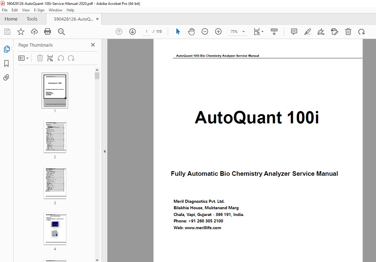
Meril AutoQuant 100i Service Manual – PDF DOWNLOAD
Description
This Meril AutoQuant 100i service manual PDF is a vital guide for service engineers maintaining the AutoQuant 100i fully automatic biochemistry analyzer from Meril Diagnostics Pvt. Ltd. It offers a comprehensive biochemistry analyzer troubleshooting guide, detailing error diagnostics, system checks, and resolutions for issues in photometric systems, temperature controls, and fluidic operations. The manual includes detailed AutoQuant 100i installation instructions, from unpacking to environmental requirements, power setup, and step-by-step assembly processes.
Key chapters explore the fluidic system diagram for AutoQuant 100i, illustrating diagrams, part views, and operational steps for precise fluid handling. The hardware structure of biochemistry analyzer is thoroughly explained, covering sample/reagent trays, reaction trays, probes, mixers, syringes, washing units, photometric systems, sensors, and circuit boards like main, stepper motor driver, power distribution, photometer, barcode reader, liquid level sensor, opto, and temperature sensor boards.
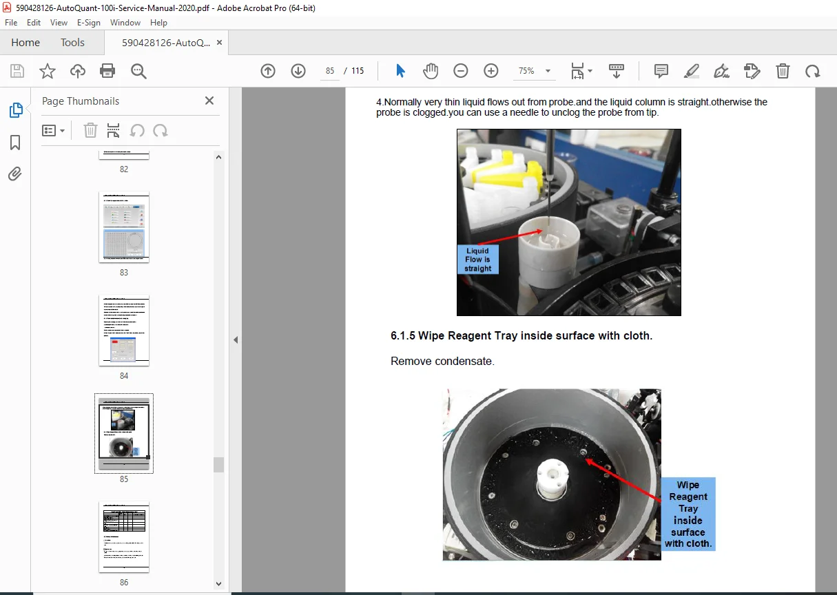
Component replacement procedures for AutoQuant 100i guide safe disassembly, adjustments, and replacements of key parts, ensuring minimal downtime. Temperature control processes for reaction trays and water tanks are detailed with controller settings. Visual aids include diagrams, assembly views, and photos throughout.
Table of Contents
(Extracted and Categorized with Subsections and Page References; No Separate Index or Bookmarks Present):
- Chapter 1: Introduction Of Analyzer (Page 4)
- 1.1 System Overview
- 1.1.1 Analyzer View
- 1.1.2 Composition of Analyzer
- 1.1.2.1 Sample/Reagent Tray Assembly (Page 6)
- 1.1.2.2 Reaction Tray Assembly and Temperature Control System (Page 10)
- 1.1.2.3 Photometric System (Page 12)
- 1.1 System Overview
- Chapter 2: Installation (Page 12)
- 2.1 Unpacking
- 2.2 Installation Environment Requirements
- 2.2.1 Installation Environment Requirements (Page 13)
- 2.2.2 Power Requirements (Page 14)
- 2.2.3 Temperature and Humidity Requirements (Page 15)
- 2.2.4 Space Requirements (Page 15)
- 2.3 Installation Process (Page 15)
- Chapter 3: Fluidic System (Page 29)
- 3.1 TC220 Analyzer Fluidic System
- 3.1.1 Fluidic Diagram (Page 29)
- 3.1.2 View Pictures of Analyzer Parts (Page 30)
- 3.1.3 Fluidic system steps instruction (Page 31)
- 3.1 TC220 Analyzer Fluidic System
- Chapter 4: Hardware Structure (Page 33)
- 4.1 Sample /reagent tray (Page 33)
- 4.2 Reaction tray and drive assembly (Page 34)
- 4.3 Optical Sensor (Page 36)
- 4.4 Sample/Reagent probe and drive assembly (Page 37)
- 4.5 Mixer probe and drive assembly (Page 38)
- 4.6 Sample/reagent syringe and drive assembly (Page 38)
- 4.7 7-steps washing unit and drive assembly (Page 39)
- 4.8 Photometric System (Page 40)
- 4.9 Temperature control process of Reaction Tray (Page 42)
- 4.10 Water Temperature Control process of water tank (Page 44)
- 4.11 System Power Supply (Page 45)
- 4.12 List of Board assemblies (Page 45)
- 4.13 Circuit board function description (Page 47)
- 4.13.1 Main board function (Page 47)
- 4.13.2 Stepper motor driver Board (Page 49)
- 4.13.3 Power supply distribution Board (Page 50)
- 4.13.4 Photometer Board (Page 51)
- 4.13.5 Barcode reader Board (Page 52)
- 4.13.6 Liquid level sensor Board (Page 54)
- 4.13.7 Opto Board (Page 54)
- 4.13.8 Temperature sensor Board (Page 55)
- 4.13.9 Temperature controller setting (Page 55)
- Chapter 5: Component Adjustment and Replacement (Page 59)
- 5.1 Signal process board voltage adjustment (Page 59)
- 5.2 Reaction tray position adjustment (Page 60)
- 5.3 Halogen Lamp replacement (Page 61)
- 5.4 Sample/reagent probe position adjustment (Page 63)
- 5.4.1 Wash well position for sample/reagent probe (Page 64)
- 5.4.2 Cuvette position for sample/reagent probe (Page 65)
- 5.4.3 Sample position for sample/reagent probe (Page 66)
- 5.4.4 Reagent position for sample/reagent probe (Page 67)
- 5.5 Sample/reagent probe replacement (Page 69)
- 5.6 Mixer probe position adjustment (Page 71)
- 5.6.1 Wash well position for mixer probe (Page 71)
- 5.6.2 Cuvette position for mixer probe (Page 73)
- 5.7 Mixer probe replacement (Page 74)
- 5.8 Synchronous belt replacement (Page 75)
- 5.9 Light filter replacement (Page 76)
- 5.10 Peristaltic Tube Maintenance or Replacement (Page 80)
- Chapter 6: Maintenance (Page 85)
- 6.1 Daily Maintenance
- 6.1.1 Check the distilled water volume of water bucket (Page 85)
- 6.1.2 Check waste solution (Page 85)
- 6.1.3 Check the signal value of all cuvettes (Page 86)
- 6.1.4 Check sample/reagent probe clogging (Page 86)
- 6.2 Weekly Maintenance
- 6.2.1 Clean sample/reagent probe and mixer probe (Page 88)
- 6.2.2 Clean two wash well (Page 88)
- 6.2.3 Clean sample and reagent tray (Page 89)
- 6.2.4 Clean the reaction tray (Page 89)
- 6.2.5 Clean 7-steps washing needles (Page 89)
- 6.2.6 Clean cuvettes using wash solution (Page 89)
- 6.2.7 Check the signal value of all cuvettes (Page 90)
- 6.3 Monthly Maintenance
- 6.3.1 Clean incubation groove of reaction tray (Page 91)
- 6.3.2 Clean the panel of machine (Page 92)
- 6.3.3 Clean distilled water bucket (Page 92)
- 6.3.4 Clean waste solution bucket (Page 93)
- 6.3.5 Clean dust screen (Page 94)
- 6.1 Daily Maintenance
- Appendix A: Spare Part List (Page 95)
- Appendix B: Diagram (Page 96)
- Chapter 7: ISE Module (Page 98)
- 7.1 ISE Module Access (Page 98)
- 7.2 ISE Module Parts (Page 98)
- Chapter 1: Introduction Of Analyzer (Page 4)
- 2.2 Installation Environment Requirements
- 2.2.1 Installation Environment Requirements (Page 13)
- 2.2.2 Power Requirements (Page 14)
- 2.2.3 Temperature and Humidity Requirements (Page 15)
- 2.2.4 Space Requirements (Page 15)
- 2.3 Installation Process (Page 15)
- 2.2 Installation Environment Requirements
- Chapter 3: Fluidic System (Page 29)
- 3.1 TC220 Analyzer Fluidic System
- 3.1.1 Fluidic Diagram (Page 29)
- 3.1.2 View Pictures of Analyzer Parts (Page 30)
- 3.1.3 Fluidic system steps instruction (Page 31)
- 3.1 TC220 Analyzer Fluidic System
- Chapter 4: Hardware Structure (Page 33)
- 4.1 Sample /reagent tray (Page 33)
- 4.2 Reaction tray and drive assembly (Page 34)
- 4.3 Optical Sensor (Page 36)
- 4.4 Sample/Reagent probe and drive assembly (Page 37)
- 4.5 Mixer probe and drive assembly (Page 38)
- 4.6 Sample/reagent syringe and drive assembly (Page 38)
- 4.7 7-steps washing unit and drive assembly (Page 39)
- 4.8 Photometric System (Page 40)
- 4.9 Temperature control process of Reaction Tray (Page 42)
- 4.10 Water Temperature Control process of water tank (Page 44)
- 4.11 System Power Supply (Page 45)
- 4.12 List of Board assemblies (Page 45)
- 4.13 Circuit board function description (Page 47)
- 4.13.1 Main board function (Page 47)
- 4.13.2 Stepper motor driver Board (Page 49)
- 4.13.3 Power supply distribution Board (Page 50)
- 4.13.4 Photometer Board (Page 51)
- 4.13.5 Barcode reader Board (Page 52)
- 4.13.6 Liquid level sensor Board (Page 54)
- 4.13.7 Opto Board (Page 54)
- 4.13.8 Temperature sensor Board (Page 55)
- 4.13.9 Temperature controller setting (Page 55)
- Chapter 5: Component Adjustment and Replacement (Page 59)
This biochemistry analyzer troubleshooting guide supports efficient repairs and maintenance with practical instructions and technical insights.
File Details
- Manual Name: AutoQuant 100i Bio Chemistry Analyzer Service Manual
- Models Covered: AutoQuant 100i
- Year: 2020
- Manual PDF Quality: Clear professional scan with readable text and diagrams
- No of Pages: 115