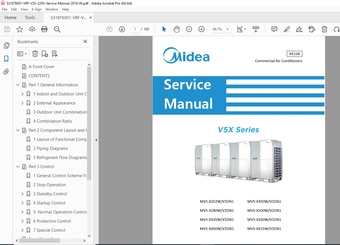
Midea V5X VRF Commercial Air Conditioner Service Manual R410A 220V 60Hz PDF
Original price was: $95.00.$15.95Current price is: $15.95.
Complete factory service manual for Midea V5X Series VRF (Variable Refrigerant Flow) commercial air conditioning systems. This 103-page technical manual covers MV5-X252W through MV5-X615W outdoor units with R410A refrigerant operating on 220V/60Hz power. Includes component layouts, refrigerant circuit diagrams, control system operation, field settings, diagnosis procedures, error code troubleshooting, and outdoor unit combination configurations. Essential reference for HVAC technicians servicing Midea VRF multi-zone commercial systems.
Description
Midea V5X VRF Commercial Air Conditioner Service Manual R410A 220V 60Hz PDF DOWNLOAD
DESCRIPTION
Midea V5X Series VRF Commercial Air Conditioner – Complete Factory Service Manual
This is the official factory service manual for Midea V5X Series VRF (Variable Refrigerant Flow) Systems – advanced commercial HVAC solutions designed for multi-zone cooling and heating in commercial buildings, offices, hotels, and large facilities. Published in June 2018 (Revision 201610), this professional technical manual is essential for HVAC service technicians, contractors, and facility engineers responsible for installing, maintaining, and servicing these sophisticated climate control systems.
With 103 pages of comprehensive technical documentation, this manual provides complete coverage of system architecture, component layouts, refrigerant circuits, control operations, field configuration, and advanced troubleshooting procedures for V5X Series VRF systems.
Revision: 201610 (June 2018)
Refrigerant: R410A
Power Supply: 220V/60Hz
🏢 ABOUT MIDEA V5X VRF SYSTEMS
VRF (Variable Refrigerant Flow) technology allows multiple indoor units of different types and capacities to operate from single or combined outdoor units, providing independent temperature control for each zone while maximizing energy efficiency through inverter-driven variable-speed compressors.
Outdoor Unit Models Covered:
- MV5-X252W/V2DN1 (9 HP / 25.2 kW / 86.0 kBtu/h)
- MV5-X280W/V2DN1 (10 HP / 28.0 kW / 95.5 kBtu/h)
- MV5-X335W/V2DN1 (12 HP / 33.5 kW / 114.3 kBtu/h)
- MV5-X400W/V2DN1 (14 HP / 40.0 kW / 136.5 kBtu/h)
- MV5-X450W/V2DN1 (16 HP / 45.0 kW / 153.5 kBtu/h)
- MV5-X500W/V2DN1 (18 HP / 50.0 kW / 170.6 kBtu/h)
- MV5-X560W/V2DN1 (20 HP / 56.0 kW / 191.1 kBtu/h)
- MV5-X615W/V2DN1 (22 HP / 61.5 kW / 209.9 kBtu/h)
Key System Features:
- R410A Refrigerant – Environmentally improved refrigerant
- Inverter Technology – Variable-speed compressor operation
- Multiple Outdoor Unit Combinations – Up to 4 units combined
- Wide Indoor Unit Selection – Multiple types and capacities
- Flexible Capacity Ratio – 50% to 130% indoor/outdoor ratio
- Advanced Controls – Microprocessor-based system management
- Energy Efficiency – Optimized operation for reduced power consumption
Compatible Indoor Unit Types:
- One-way Cassette (Q1)
- Two-way Cassette (Q2)
- Compact Four-way Cassette (Q4-C)
- Four-way Cassette (Q4)
- Low Static Pressure Duct (T3)
- Medium Static Pressure Duct (T2)
- High Static Pressure Duct (T1)
- Wall-mounted (G)
- Ceiling & Floor (DL)
- Floor Standing (F)
- Console (Z)
- Fresh Air Processing Unit
Indoor Unit Capacity Range:
- Minimum: 0.6 HP (1.8 kW / 6.1 kBtu/h)
- Maximum: 16 HP (45.0 kW / 153.5 kBtu/h)
📋 COMPREHENSIVE MANUAL CONTENTS
PART 1 – GENERAL INFORMATION (Pages 3-10)
- Indoor and Outdoor Unit Capacities
Standard Indoor Units
- Complete capacity range table (0.6 HP to 16 HP)
- Indoor unit type abbreviation codes
- Capacity index system explanation
- kW, kBtu/h, and HP conversions
- Available capacities for each indoor unit type:
- Q1 (One-way Cassette): 1.8-7.1 kW
- Q2 (Two-way Cassette): 2.2-7.1 kW
- Q4-C (Compact Four-way): 2.2-7.1 kW
- Q4 (Four-way Cassette): 2.8-7.1 kW
- T3 (Low Static Duct): 1.8-14.0 kW
- T2 (Medium Static Duct): 2.2-14.0 kW
- T1 (High Static Duct): 5.6-45.0 kW
- G (Wall-mounted): 2.2-11.2 kW
- DL (Ceiling & Floor): 2.2-16.0 kW
- F (Floor Standing): 2.8-11.2 kW
- Z (Console): 2.2-9.0 kW
Fresh Air Processing Unit
- Fresh air unit capacity specifications
- Ventilation capabilities
Outdoor Units
- Single outdoor unit specifications (9 HP to 22 HP)
- Power consumption data
- Physical dimensions and weight
- Operating ranges
- Refrigerant charge amounts
- Maximum piping lengths
- Maximum elevation differences
- External Appearance
- Indoor unit dimensional drawings
- Outdoor unit dimensional drawings
- Service panel locations
- Access point identification
- Component locations
- Outdoor Unit Combinations
- Single Outdoor Unit Configuration
- Two Outdoor Units Combined
- Three Outdoor Units Combined
- Four Outdoor Units Combined
- Combined system capacity tables
- Example: 40 HP model (MV5-X1115W/V2DN1) configuration
- Piping connection requirements for combined systems
- Electrical wiring for multiple units
- Combination Ratio
- Indoor/Outdoor capacity matching guidelines
- Minimum ratio: 50% of outdoor capacity
- Maximum ratio: 130% of outdoor capacity
- Capacity index calculation method
- System balance recommendations
- Over-capacity and under-capacity implications
PART 2 – COMPONENT LAYOUT AND REFRIGERANT CIRCUITS (Pages 11-20)
- Outdoor Unit Component Layout
- Complete component location diagrams
- Major Components:
- Inverter compressor(s)
- Fixed-speed compressor (select models)
- Heat exchanger (outdoor coil)
- Electronic expansion valves (EEV)
- Four-way valve
- Accumulator
- Oil separator
- Service valves (gas and liquid)
- Pressure sensors (high and low)
- Temperature sensors (thermistors)
- Outdoor fan motors
- Main control board
- Inverter board
- Reactor
- Noise filter
- Terminal blocks
- Indoor Unit Component Layout (Various Types)
- Air filters
- Heat exchanger (indoor coil)
- Electronic expansion valve
- Drain pan
- Fan motor
- Control board
- Temperature sensors
- Remote control receiver
- Refrigerant Circuit Diagrams
Single Outdoor Unit Circuit
- Cooling mode refrigerant flow
- Heating mode refrigerant flow
- Component operation in each mode
- Valve positions (open/closed)
- Refrigerant state (liquid/gas/mixed)
Combined Outdoor Unit Circuits
- 2-unit, 3-unit, 4-unit configurations
- Refrigerant distribution
- Oil equalization piping
- High/low pressure gas piping
- Liquid piping connections
Multi-Indoor Unit Configuration
- Branch box (refnet) connections
- Individual indoor unit circuits
- Refrigerant distribution logic
- Piping System Schematics
- Main gas piping
- Main liquid piping
- Branch piping
- Oil return piping (combined systems)
- Service port locations
- Component Functions
- Compressor operation principles
- Four-way valve switching mechanism
- EEV control methodology
- Accumulator function
- Oil separator operation
- Heat exchanger design
PART 3 – CONTROL (Pages 21-34)
- Control System Architecture
- Microprocessor-based control
- Master/slave configuration (combined systems)
- Communication protocols
- Sensor inputs
- Actuator outputs
- Operation Modes
- Cooling mode
- Heating mode
- Auto changeover
- Fan only
- Dry/dehumidification mode
- Compressor Control
- Inverter Compressor Control
- Variable frequency drive operation
- Capacity modulation algorithm
- Target frequency calculation
- Load-based frequency adjustment
- Startup frequency control
- Operating frequency limits
- Fixed-Speed Compressor Control (if equipped)
- ON/OFF cycling
- Load balancing with inverter compressor
- Startup sequencing
- Inverter Compressor Control
- Temperature Control
- Target temperature calculation
- Room temperature sensing
- Coil temperature monitoring
- Outdoor ambient temperature compensation
- Superheat control
- Subcooling control
- Electronic Expansion Valve (EEV) Control
- Opening degree calculation
- Superheat target values
- PI control algorithm
- Fast response adjustments
- Capacity matching optimization
- Four-Way Valve Control
- Cooling mode position
- Heating mode position
- Switching timing
- Mode transition procedures
- Fan Control
- Outdoor Fan Control
- Multi-speed operation
- Ambient temperature-based adjustment
- Condensing pressure control
- Energy optimization
- Indoor Fan Control
- Fan speed settings (low/medium/high/auto)
- Airflow adjustment based on capacity
- Quiet mode operation
- Auto fan speed logic
- Outdoor Fan Control
- Defrost Control
- Defrost initiation conditions
- Defrost operation sequence
- Defrost termination logic
- Hot gas defrost procedure
- Indoor unit protection during defrost
- Oil Return Control
- Periodic oil return operation
- High-frequency compressor running
- Oil collection from remote locations
- Combined system oil management
- Protection Controls
- High Pressure Protection
- High pressure switch monitoring
- Pressure sensor monitoring
- Capacity reduction procedures
- System shutdown thresholds
- Low Pressure Protection
- Low pressure detection
- Refrigerant shortage indication
- Leak prevention shutdown
- Compressor Protection
- Overcurrent protection
- High discharge temperature protection
- Minimum running time enforcement
- Minimum stop time enforcement
- Inverter Protection
- DC bus overvoltage/undervoltage
- IPM temperature protection
- Overcurrent shutdown
- Freeze Protection
- Indoor coil freeze detection
- Anti-freeze operation
- High Pressure Protection
- Communication System
- Indoor-outdoor unit communication
- Remote control communication
- Centralized control interface
- Error code transmission
PART 4 – FIELD SETTINGS (Pages 35-40)
- DIP Switch Settings
- Outdoor unit DIP switch configuration
- Address setting for combined systems
- Parameter selections
- Default settings
- Remote Control Field Settings
- Accessing field setting mode
- Available parameters:
- Indoor unit address setting
- Capacity setting
- Pipe length correction
- Height difference correction
- Oil return interval
- Defrost settings
- Fan speed settings
- Temperature compensation
- Refrigerant type confirmation
- And more…
- Setting procedures with button sequences
- Saving and exiting field settings
- PC Board Parameter Settings
- Service mode access
- Advanced parameter modification
- System configuration settings
- Protection parameter adjustments
- Test Run Mode
- Forced cooling operation
- Forced heating operation
- Individual component testing
- Sensor reading verification
- Address Assignment
- Indoor unit addressing (combined systems)
- Outdoor unit master/slave designation
- Communication verification
PART 5 – DIAGNOSIS AND TROUBLESHOOTING (Pages 41-103)
- Self-Diagnosis System
- Error code generation logic
- Error history storage
- Error code retrieval from remote control
- LED indicator patterns
- Error Code List and Troubleshooting
Communication Errors:
- Indoor-outdoor communication failure
- Multiple indoor unit communication errors
- Remote control communication failure
- Wiring verification procedures
- Signal testing methods
Sensor Errors:
- Room temperature sensor malfunction
- Coil temperature sensor errors
- Outdoor ambient sensor failure
- Discharge temperature sensor issues
- Suction temperature sensor problems
- Liquid pipe temperature sensor errors
- Sensor resistance testing
- Wiring continuity checks
- Sensor replacement procedures
Compressor Errors:
- Compressor overcurrent
- High discharge temperature
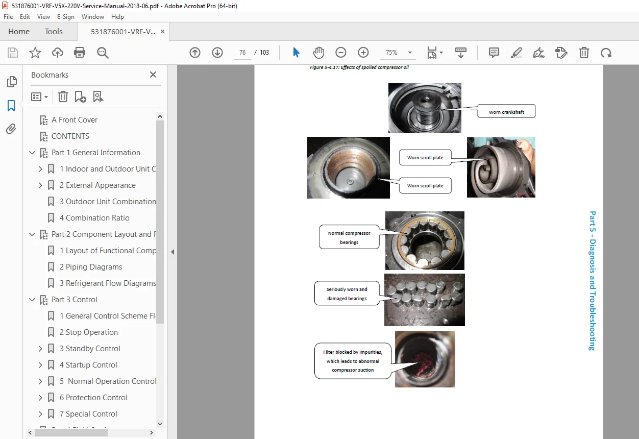
- Compressor lock/seizure
- Starting failure
- Position sensor error (inverter compressor)
- Diagnostic procedures
- Electrical testing
- Mechanical inspection
Pressure Errors:
- High pressure switch actuation
- High pressure sensor abnormal reading
- Low pressure detection
- Refrigerant shortage indication
- Overcharge detection
- Pressure measurement procedures
- Refrigerant charge verification
Inverter Errors:
- IPM protection
- DC bus voltage abnormal
- Current sensor error
- Inverter overheating
- Communication error with inverter board
- Voltage measurements
- Component testing
Four-Way Valve Errors:
- Switching failure
- Incomplete mode change
- Coil resistance testing
- Mechanical inspection
EEV (Electronic Expansion Valve) Errors:
- Valve operation failure
- Position sensor error
- Coil open/short circuit
- Replacement procedures
System Errors:
- Phase sequence error
- Freeze protection activation
- Outdoor unit combination error
- Capacity ratio error
- Configuration mismatch
- Each Error Code Section Includes:
- Error code number and description
- Possible causes
- Systematic diagnostic flowchart
- Step-by-step troubleshooting procedure
- Measurement points and expected values
- Component testing methods
- Repair/replacement procedures
- Verification after repair
- Symptom-Based Troubleshooting
- Unit does not operate
- Poor cooling performance
- Poor heating performance
- Abnormal noise
- Water leakage
- Frequent cycling
- Continuous operation
- Fan problems
- Systematic diagnostic approach
- Pressure and Temperature Diagnosis
- Normal operating pressure ranges
- Normal operating temperature ranges
- Pressure-temperature charts for R410A
- Abnormal pressure diagnosis
- Refrigerant charge assessment
- Electrical Troubleshooting
- Voltage measurements at key points
- Current measurements
- Resistance testing
- Continuity checks
- Control signal verification
🔧 CRITICAL SERVICE FEATURES
✅ R410A VRF System – Modern refrigerant technology
✅ 8 Outdoor Unit Models – 9 HP to 22 HP range
✅ Multiple Indoor Unit Types – 11 different configurations
✅ Combination Configurations – Up to 4 outdoor units combined
✅ Complete Error Code Database – Comprehensive diagnostic procedures
✅ Refrigerant Circuit Diagrams – All operation modes illustrated
✅ Field Settings Guide – Complete configuration procedures
✅ Control System Theory – Inverter and protection controls explained
✅ Component Layouts – Detailed location diagrams
✅ Troubleshooting Flowcharts – Systematic diagnostic approach
📄 FILE DETAILS
| Specification | Details |
|---|---|
| Manual Title | V5X Series VRF Service Manual |
| Equipment Type | Variable Refrigerant Flow (VRF) Commercial Air Conditioner |
| Manufacturer | Midea |
| Models Covered | MV5-X252W through MV5-X615W (9-22 HP) |
| Refrigerant | R410A |
| Power Supply | 220V/60Hz |
| Publication Date | June 2018 (Revision 201610) |
| Total Pages | 103 pages |
| File Format | PDF (searchable and printable) |
| PDF Quality | ⭐⭐⭐⭐⭐ Excellent – Factory service manual quality |
| Language | English |
🏢 COMPATIBLE SYSTEMS
Outdoor Units (220V/60Hz):
- MV5-X252W/V2DN1 (9 HP / 25.2 kW)
- MV5-X280W/V2DN1 (10 HP / 28.0 kW)
- MV5-X335W/V2DN1 (12 HP / 33.5 kW)
- MV5-X400W/V2DN1 (14 HP / 40.0 kW)
- MV5-X450W/V2DN1 (16 HP / 45.0 kW)
- MV5-X500W/V2DN1 (18 HP / 50.0 kW)
- MV5-X560W/V2DN1 (20 HP / 56.0 kW)
- MV5-X615W/V2DN1 (22 HP / 61.5 kW)
Indoor Unit Types:
- All Midea V5X compatible cassette types
- All Midea V5X compatible duct types
- All Midea V5X compatible wall/floor/console types
- Fresh air processing units
Applications:
- Commercial office buildings
- Retail stores and shopping centers
- Hotels and resorts
- Restaurants and cafeterias
- Healthcare facilities
- Educational institutions
- Multi-tenant buildings
- Light industrial facilities
💡 WHO NEEDS THIS MANUAL?
- HVAC Service Technicians – Installation, maintenance, and repair
- VRF System Installers – Commercial HVAC contractors
- Building Maintenance Engineers – Facility management teams
- Mechanical Contractors – MEP (Mechanical, Electrical, Plumbing) firms
- HVAC Service Companies – Independent service providers
- Midea Authorized Dealers – Official service support
- Facility Managers – Large commercial buildings with VRF systems
- Technical Training Departments – HVAC technician education
🎯 WHY THIS MANUAL IS ESSENTIAL
Official Midea Documentation: Factory service manual providing accurate technical information for V5X Series VRF systems.
VRF Technology Expertise: Understanding VRF systems requires specialized knowledge of refrigerant distribution, capacity control, and multi-unit coordination – this manual provides complete technical foundation.
R410A System Requirements: Working with R410A refrigerant requires specific procedures and safety knowledge due to higher operating pressures compared to older refrigerants.
Minimize Downtime: In commercial buildings, HVAC failures impact occupant comfort and business operations. This manual enables rapid diagnosis and repair.
Cost Savings: Avoid expensive manufacturer service calls by developing in-house VRF service capabilities with proper technical documentation.
Multi-Unit Complexity: Combined outdoor unit configurations require understanding of master/slave operation, oil management, and system balancing – all covered in this manual.
Complete Error Code Coverage: Comprehensive troubleshooting procedures for all system error codes enable accurate diagnosis and efficient repair.
⚙️ TECHNICAL HIGHLIGHTS
System Capabilities:
- Capacity range: 9 HP to 22 HP outdoor units
- Combination potential: Up to 4 outdoor units (40+ HP systems)
- Indoor capacity ratio: 50% to 130% of outdoor capacity
- Wide indoor unit selection: 11 different types
- Inverter technology: Variable-speed compressor operation
Refrigerant System:
- R410A refrigerant (HFC)
- Higher operating pressures than R22
- Environmentally improved (zero ODP)
- Liquid charging required
Control Features:
- Microprocessor-based control
- Independent zone control
- Automatic capacity modulation
- Defrost control
- Oil return management
- Multiple protection systems
Power Supply:
- 220V/60Hz systems
- Suitable for North American markets (non-US)
- Commercial power requirements
⚡ INSTANT DOWNLOAD – SERVICE SUPPORT IMMEDIATELY!
Stop searching for incomplete VRF system information when servicing Midea V5X commercial air conditioners! This comprehensive 103-page factory service manual gives you complete technical documentation for all MV5-X models from 9 HP to 22 HP. From understanding refrigerant circuits in combined outdoor unit configurations to troubleshooting complex error codes, from field settings and capacity ratio calculations to inverter compressor control theory – everything you need is here. Whether you’re installing a new multi-zone VRF system, performing preventive maintenance, or diagnosing performance issues, this manual provides factory-level expertise. Download instantly and have professional VRF service capabilities for Midea’s advanced climate control technology!
Pricing Rationale:
- Professional VRF service manual (103 pages)
- Commercial HVAC equipment ($15,000-$100,000+ systems)
- Covers 8 outdoor unit models (9-22 HP range)
- R410A refrigerant system documentation
- Complete error code troubleshooting procedures
- Refrigerant circuit diagrams for all configurations
- Field settings and configuration guidance
- Essential for commercial HVAC technicians
- Saves thousands in service call costs
- Midea brand – growing market presence
- Moderate page count but focused technical content