Mimaki CJV30-60 Series Service Manual PDF – DOWNLOAD
Original price was: $95.00.$19.95Current price is: $19.95.
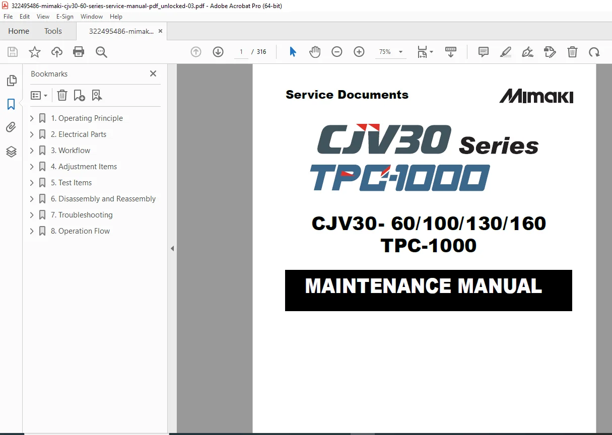
Professional service manual for Mimaki CJV30-60/100/130/160 printer/cutter series with TPC-1000. Complete 316-page technical documentation covering maintenance procedures, electrical schematics, troubleshooting guides, adjustment functions, and disassembly workflows. Includes detailed error code lists, ink system operations, circuit board specifications, and test procedures. Essential for technicians servicing Mimaki wide-format print and cut equipment. Instant PDF download.
Description
Mimaki CJV30-60 Series Service Manual Complete Maintenance Guide PDF DOWNLOAD
DESCRIPTION
Complete Service Documentation for Mimaki CJV30 Series Printer/Cutters
This comprehensive maintenance manual provides complete technical documentation for the Mimaki CJV30-60, CJV30-100, CJV30-130, and CJV30-160 wide-format printer/cutter systems along with the TPC-1000 model. Created by Mimaki Engineering Co., Ltd., this professional-grade service manual is your essential resource for maintaining, troubleshooting, and repairing these sophisticated hybrid printing and cutting machines.
📋 FILE DETAILS
- Manual Name: CJV30 Series Maintenance Manual (D500387)
- Models Covered: CJV30-60, CJV30-100, CJV30-130, CJV30-160, TPC-1000
- Year: 2010 (Version 1.30 – November 2010)
- Manual Format: PDF (optimized, searchable)
- Page Count: 316 pages
- File Size: ~20 MB
- PDF Quality: Excellent – original manufacturer documentation with clear diagrams
📖 COMPREHENSIVE MANUAL CONTENTS
1. OPERATING PRINCIPLE (Section 1)
- 1.1 Basic Operation
- Main Switch Power ON/OFF procedures
- Sub Switch Power ON sequence
- Initial machine operation protocols
- Media width detection systems
- Clamp pressure switching mechanisms
- Head connection operations (print head & cut head)
- Registration mark detection procedures
- 1.2 Maintenance Functions
- CARRIAGE OUT procedures
- WIPER REPLACE operations
- NOZZLE WASH protocols
- PUMP TUBE WASH procedures
- CR.MAINTENANCE functions
- FILL UP INK operations
- DISCHARGE & WASH procedures
- Maintenance washing liquid handling
- Waste ink tank warning systems
- Aqua to Sol ink exchange procedures
- 1.3 Ink System Architecture
- Complete ink system configuration diagrams
- Ink system error monitoring protocols
- Supply cartridge control and selection
- Cartridge LED control systems
- Supply valve control mechanisms
- Remaining ink monitoring procedures
- Use-up cleaning protocols
- Ink suction and discharge control
- Initial filling procedures (standard & advanced)
- Ink expiry month tracking and extension
- 1.4 Print & Cut Operations
- Integrated print/cut workflow procedures
- Registration and alignment protocols
2. ELECTRICAL PARTS (Section 2)
- 2.1 Block Diagrams
- Internal connection diagrams (main body)
- External connection diagrams
- 2.2 Operating Descriptions
- Detailed operation explanations for all electrical systems
- 2.3 Circuit Board Specifications
- Power Supply PCB Assembly
- Main PCB Assembly
- PRAM PCB Assembly
- Regenerative Resistivity PCB Assembly
- Cutter Driver PCB Assembly
- Station PCB Assembly
- X-axis Motor Relay PCB Assembly
- Ink Slider PCB Assembly
- Cutter Slider PCB Assembly
- Head Memory PCB Assembly
- LED PCB Assembly
- Keyboard PCB Assembly
- Take-up PCB Assembly
3. WORKFLOW PROCEDURES (Section 3)
- 3.1 Ink Related Parts Replacement
- Head Unit replacement procedures
- Cap Assembly replacement
- Cartridge Assembly replacement
- Wiper Unit replacement
- 3.2 Cut Head Carriage
- Pen Assembly and LED Pointer replacement
- Auto Cutter Assembly replacement
- Mark Assembly replacement
- 3.3 Driving Parts
- X-axis Motor replacement
- Y-axis Motor replacement
- Y Drive Belt replacement
- Linear Encoder Scale replacement
- GR Roller Assembly replacement
- 3.4 Electrical Parts Replacement
- Main PCB Assembly replacement procedures
4. ADJUSTMENT ITEMS (Section 4)
- 4.1 Operations Matrix
- Complete matrix of operations and adjustments
- 4.2 Adjustment Functions
- HEAD ADJUST: SLANT ADJUST, DROP.POS ADJUST
- EDGE ADJUST calibration
- MEDIA COMP.2 settings
- CAPPING adjustments
- HEAD ID configuration
- HEAD WASH procedures
- 500mm SQUARE test pattern
- PEN PRESSURE calibration
- LANDING position adjustment
- PHOTO SENSOR: SENSOR LV., POSITION adjustments
- GR/PR POSITION calibration
- MOTOR CURRENT optimization
- PRINT/CUT POS. alignment
- SERIAL No. and DEALER No. configuration
- DEFAULT SET restoration
- REPLACE PARTS tracking
- 4.3 Mechanical Adjustments
- Mark sensor location adjustment
- Cutter mounting location adjustment
- Station height adjustment
- Wiper height adjustment
- Encoder sensor positioning
- Roll holder centering
- Wiper drive link positioning
5. TEST ITEMS (Section 5)
- 5.1 Comprehensive Test Functions
- CHECK PATTERN: PATTERN, COLOR CHART, DROP.POS CHK
- ALL PATTERN test
- MOTOR TEST: X SERVO, Y SERVO, XY SERVO, WIPER, PUMP, TAKE-UP motors
- HEATER TEST: TEMPERATURE, SSR
- ACTION TEST protocols
- SENSOR TEST procedures
- OPTION testing
- KEYBOARD LED and KEYBOARD TEST
- LCD TEST
- TIMER CHECK
- MEMORY CHECK
- SKEW CHECK
- TEMP.CHECK: HEAD, NOZZLE, HEAT SINK, SLIDER temperatures
- LINEAR ENCODER testing
- INK CARTRIDGE: PACK&END SENSOR, CARTRIDGE VALVE, INK-IC CHECK, CARTRIDGE LED
- WASH CARTRIDGE: Complete testing suite
- HEAD JOINT verification
- PINCH ROLLER testing
- CUT PATTERN: TEST, 2m, 10m, QUALITY, SQUARE patterns
- 5.2 Other Specialized Tests
- COM short circuit determination
- Print head damage checking
- Main PCB Assembly damage checking
- Ink Slider PCB damage verification
- HDC FFC COM Line conduction checking
- HDC FFC Data Line conduction checking
6. DISASSEMBLY AND REASSEMBLY (Section 6)
- 6.1 Cover Layout
- Complete cover identification and removal
- 6.2 Ink-Related Parts
- Head Unit cleaning, removal, and mounting
- Pump Motor disassembly
- Pump Assembly procedures
- Cap Assembly and Cap Head Assembly
- Valve Assembly
- Joint changing procedures
- 6.3 Cut Head Carriage
- Pen Assembly and LED Pointer
- Auto Cutter Assembly
- Mark Assembly
- 6.4 Drive System
- X-axis Motor
- Y-axis Motor
- Y Drive Pulley and Belt
- Linear Encoder Scale
- Wiper Unit
- GR Roller Assembly
- Take-up Motor
- C Connecting Hook
- P Head Connecting Hook
- Clamp Assembly
- 6.5 Electrical Parts Disassembly
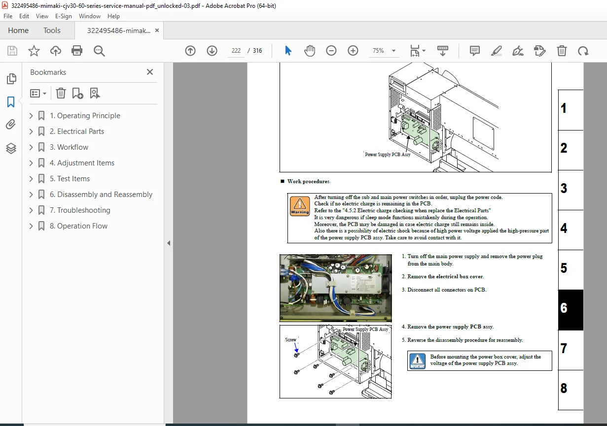
- Power Supply PCB Assembly
- Main PCB Assembly
- PRAM PCB Assembly
- Head Memory PCB Assembly
- LED PCB Assembly
- Station PCB Assembly
- Paper Sensor
- X-axis Motor Relay PCB Assembly
- Ink Slider PCB Assembly
- Cutter Slider PCB Assembly
- Keyboard PCB Assembly
- Encoder PCB Assembly
- Fan Motor
- Take-up Motor PCB Assembly
- ID Contact PCB Assembly
- Detector Assembly
- Main PCB fuse replacement procedure
- 6.6 Sensors
- Complete sensor layout diagrams
7. TROUBLESHOOTING (Section 7)
- 7.1 Error and Malfunction Details
- Complete Error Messages List (ERROR01 through ERROR211)
- Warning Messages List with causes and remedies
- Troubleshooting procedures for issues without error messages
- 7.2 Detailed Malfunction Resolution
- Y Drive Belt noise troubleshooting
- Media attachment to platen issues
- Electrical troubleshooting procedures
- Y Drive Belt damage diagnosis
- Heater temperature problems
- 7.3 Diagnostic Checksheets
- PCB damage checksheet templates
8. OPERATION FLOW (Section 8)
- 8.1 Basic Operations
- Startup procedures
- Initial filling workflows
- Media detection sequences
- 8.2 Print Mode Operations
- LOCAL/REMOTE operation modes
- SETUP configurations
- MAINTENANCE procedures
- MACHINE SETUP parameters
- 8.3 Cut Mode Operations
- LOCAL/REMOTE operation modes
- SETUP configurations
- MAINTENANCE procedures
- Number of copies settings
- 8.4 Common Settings
- COMMON SETUP parameters
- 8.5 Service Mode
- #ADJUST functions
- #TEST procedures
- #PARAMETER configurations
🔧 PERFECT FOR:
✅ Authorized Service Technicians – Complete factory service procedures ✅ In-House Maintenance Teams – Reduce downtime with proper maintenance protocols ✅ Equipment Owners – Understand your machine’s operation and basic troubleshooting ✅ Technical Training Programs – Comprehensive educational resource ✅ Parts Departments – Detailed parts identification and replacement procedures
💡 KEY FEATURES OF THIS MANUAL:
- Multi-Color Ink System Support: 4-color, 6-color, 6-color+W, 7-color, and 8-color ink configurations
- Hybrid Print/Cut Technology: Complete documentation for both printing and cutting operations
- Error Code Database: Exhaustive error message list with specific causes and remedies
- Circuit Diagrams: Detailed electrical schematics for all PCB assemblies
- Step-by-Step Procedures: Clear, illustrated instructions for all service tasks
- Adjustment Protocols: Precise calibration procedures for optimal performance
- Preventive Maintenance: Scheduled maintenance procedures to extend equipment life
- Safety Information: Important warnings and cautions throughout
🎯 TECHNICAL SPECIFICATIONS COVERED:
- Firmware Version: 2.00 compatibility
- Resolution Settings: Including 360×360 dpi configurations
- Print Head Technology: Complete head adjustment and maintenance
- Cutter Systems: Pen, LED pointer, and auto cutter maintenance
- Media Handling: Clamp pressure settings, pinch roller configurations
- Take-up Systems: Motor control and operation procedures
- Heater Systems: Temperature monitoring and SSR testing
⚡ INSTANT DOWNLOAD – Start servicing your Mimaki CJV30 equipment immediately! This professional service manual provides everything you need to maintain peak performance, minimize downtime, and extend the service life of your valuable wide-format printing and cutting investment.
Justification:
- 316 pages of professional OEM documentation
- Covers multiple models (CJV30-60/100/130/160 + TPC-1000)
- Comprehensive technical content (8 major sections)
- Expensive equipment (reduces service costs significantly)
- Comparable Mimaki service manuals sell for $35-$75
- Professional-grade technical documentation
- Instant digital delivery