Mindray BC-2800 Auto Hematology Analyzer Service Manual Complete PDF 2007
Original price was: $100.00.$32.95Current price is: $32.95.
Official factory service manual for Mindray BC-2800 Auto Hematology Analyzer. Comprehensive 109-page technical guide covering hardware architecture, fluidic systems, maintenance procedures, troubleshooting, and component replacement. Includes detailed CPU board schematics, power supply diagrams, display unit specifications, complete disassembly procedures, histogram analysis, gain adjustment, system diagnostics, error codes, and spare parts list. Essential technical reference for biomedical engineers
Description
Mindray BC-2800 Auto Hematology Analyzer Service Manual Complete 2007 PDF DOWNLOAD
DESCRIPTION
Mindray BC-2800 Auto Hematology Analyzer Complete Service Manual
This is the official factory service manual (Version 1.1) for the Mindray BC-2800 Auto Hematology Analyzer, manufactured by Shenzhen Mindray Bio-Medical Electronics Co., Ltd. This comprehensive 109-page technical manual provides complete hardware architecture, maintenance procedures, troubleshooting guides, and repair instructions for qualified biomedical equipment technicians.
File Details
- Manual Name: BC-2800 Auto Hematology Analyzer Service Manual
- Manual Version: V1.1
- Equipment Type: Automated Hematology Analyzer (Clinical Laboratory Equipment)
- Manufacturer: Shenzhen Mindray Bio-Medical Electronics Co., Ltd.
- Publication Date: April 2007
- Manual Quality: Factory Original OEM – Excellent Quality
- Total Pages: 109 pages
- Language: English
- Format: PDF (Optimized, searchable)
Important Safety Information
⚠️ Professional Use Only – This equipment is NOT intended for home/family use and must be operated by skilled/trained clinical laboratory personnel only.
⚠️ Service Authorization – Mindray is responsible for safety, reliability, and performance only when service is performed by Mindray-qualified personnel.
⚠️ Warranty – This manual is proprietary to Mindray and intended solely for reference, operation, maintenance, and repair of Mindray equipment by authorized personnel.
Complete Manual Contents
COPYRIGHT AND WARRANTY INFORMATION
- Copyright Statement – Proprietary rights and confidential work notice
- Manufacturer Responsibility – Conditions for safety and reliability
- Important Notes – Professional use requirements and operating guidelines
- Warranty Coverage
- Workmanship and materials (one year from shipment)
- Warranty limitations and exemptions
- Service and repair conditions
- Return Policy and Procedures
- Customer service authorization process
- Freight and shipping policies
- Company Contact Information
- Shenzhen headquarters details
- European authorized representative
- Phone, fax, and address listings
CHAPTER 1: HARDWARE (Pages 1-1 to 1-17)
1.1 General
- Complete schematic of CPU board architecture
- Block diagram showing major components
- System overview and component relationships
- Basic Functions of CPU Board:
- Analog signal reception (WBC/RBC/PLT counts, HGB measurement)
- Aperture voltage and vacuum/pressure monitoring
- System status monitoring (+48V, +12V, -12V analog board)
- CPU board power monitoring (+3.3V, +12V)
- Temperature monitoring
- Keypad signal processing
- Buzzer and LCD backlight control
- Control signal generation (valves, aperture zapping, HGB LED)
- LCD driving and contrast adjustment
- Keyboard, printer, and floppy drive interface
1.2 Power Supply
- Dual independent external power supplies (+5V and +12V)
- 5A fuse protection on power entries
- Voltage conversion architecture:
- +5V to +3.3V for digital components
- +3.3V to +1.5V for FPGA power
- +12.8V supply distribution
- Complete power distribution diagram
1.3 RTC (Real-Time Clock)
- Crystal oscillator specifications (X1: 45MHz, X4: 45MHz, X2: 24MHz)
- CPU clock arrangement schematic
- BCLKO main clock signal operation
1.4 CPU and Peripheral Devices
- CPU Specifications:
- MOTOROLA MCF5307 processor
- External frequency: 45MHz
- Operating frequency: 90MHz
- Processing speed: 75 MIPS
- 32-bit data bus and address bus
- 24-bit addressing mode implementation
- BDM port tuning capability (J18)
- Built-in I2C and UART controllers
- Built-in DRMA controller for memory expansion
- Watch-Dog-Timer (WDT)
- TI TPS3828 specification
- Software monitoring function
- 1.6-second feedback requirement
- Automatic restart capability
- FLASH Memory
- TE28F160 (2M bytes capacity)
- Boot program storage (BootROM)
- System initialization functions
- FPGA configuration storage
- LCD contrast settings
- SDRAM
- Two 8M-byte memory modules
- System memory configuration
- DOM (Disk-On-Module)
- 32M byte capacity
- 3.3V power supply (5V compatible)
- Control software storage
- FPGA configuration dependent operation
- RTC (Real-Time Clock)
- I2C bus connection
- 32.768KHz crystal oscillator synchronization
- Dual power mode (board power/battery backup)
- EEPROM
- 8K byte capacity
- System configuration storage
- I2C bus connection
- Online CPU write capability
- LED Indicators
- D1: +3.3V power status
- D9: +12.8V power status
- D5: DOM read/write activity
- D7: FPGA configuration status
- D20: FPGA restart indicator
- D11-D18: Software-defined system status
1.5 Analog Inputs and Outputs
- Analog signal processing architecture
- Input channel specifications
- Output signal generation
- Signal conditioning circuits
1.6 Digital Inputs and Outputs
- Digital I/O configuration
- Signal routing and control
- Interface specifications
1.7 Driving Board
- Motor Control Block:
- Serial communication circuit with photocoupler isolation (H11L1)
- Sample probe mechanism control/drive
- Syringe motor control/drive
- Position sensor drive and signal detection
- Sample Probe Motor Control:
- AT89S51 MCU with ADM705 WDT
- Elevator motor control/drive circuit
- Rotation motor control/drive circuit
- L6506 control device
- L298N drive device
- UC3610 follow-current device
- 30V drive voltage for elevator
- 12V drive voltage for rotation (ULN2068B)
- Syringe Motor System:
- P87LPC762 MCU with built-in WDT
- Aspiration and dispensing operations
- Position transducer signal detection
- Valve and Pump Driving:
- TLP521-2 photocoupler isolation
- ULN2068 drive circuit
- 12V TTL drive voltage
- Maximum 14 valves and 2 pumps capacity
- Position Transducer Circuit:
- Photocoupler position detection
- 74LS07 drive circuit
- 74LS14 signal inversion
- Motor position feedback system
- Testable Signals:
- Control signals for valves and pumps
- Motor sequence signals
- Position transducer signals
- Serial communication signals
- Reset signals
- Power supply voltage signals
1.8 Display Unit
- LCD Adapter Functions:
- CPU board to LCD connection
- FPC/FFC connector specifications (J2, J3)
- Signal cable interface (J1)
- Complete connection schematic
1.9 Keypad Adapter Functions
- Keypad Scanning System:
- 5×4 matrix configuration
- 9 I/O wires, 20 keys
- Key code reporting to main board
- LCD Brightness Control:
- Backlight on/off control
- Power indicator control
- Brightness adjustment via RV1 potentiometer
- 0.5-3V voltage range control
- Screen saver functionality
- Buzzer Control:
- 5V DC operation (<40mA)
- TLP521-2 photocoupler isolation
- 10mA control current
- Architecture:
- AT89C2051 MCU
- 11.0592MHz crystal oscillator
- 470ms reset time
- Dual power supply (+12V, +3.3V isolated)
CHAPTER 2: FLUIDIC SYSTEM (Pages 2-1 to 2-12)
2.1 Fluidic System Functions
- Diluent preparation for whole blood analysis
- Diluent preparation for prediluted sample mode
- Blood cell counting procedures
- Hemoglobin (HGB) concentration measurement
- Diluent dispensing operations
- Flush cycle implementation
- Startup cycle procedures
- Cleaning cycle operations
- Vacuum and pressure control systems
2.2 Construction of Fluidic System
- Complete fluidic system architecture
- Component layout and arrangement
- Plumbing schematic diagrams
2.3 Composition of Fluidic System
- Reagent containers and reservoirs
- Tubing and valve configurations
- Pump assemblies
- Measurement chambers
- Waste collection system
2.4 Functional Modules
- Sample Aspiration Module
- Dilution Module
- Measurement Module
- Cleaning Module
- Vacuum/Pressure Control Module
- Detailed operation of each module
- Component interaction diagrams
2.5 Counting Procedure
- Step-by-step cell counting process
- WBC (White Blood Cell) counting methodology
- RBC (Red Blood Cell) counting methodology
- PLT (Platelet) counting methodology
- HGB measurement procedure
- Quality control checkpoints
- Timing sequences and delays
CHAPTER 3: DISASSEMBLING THE ANALYZER (Pages 3-1 to 3-3)
3.1 Main Unit Structure
- Exterior component identification
- Internal component layout
- Access panel locations
- Cable routing diagrams
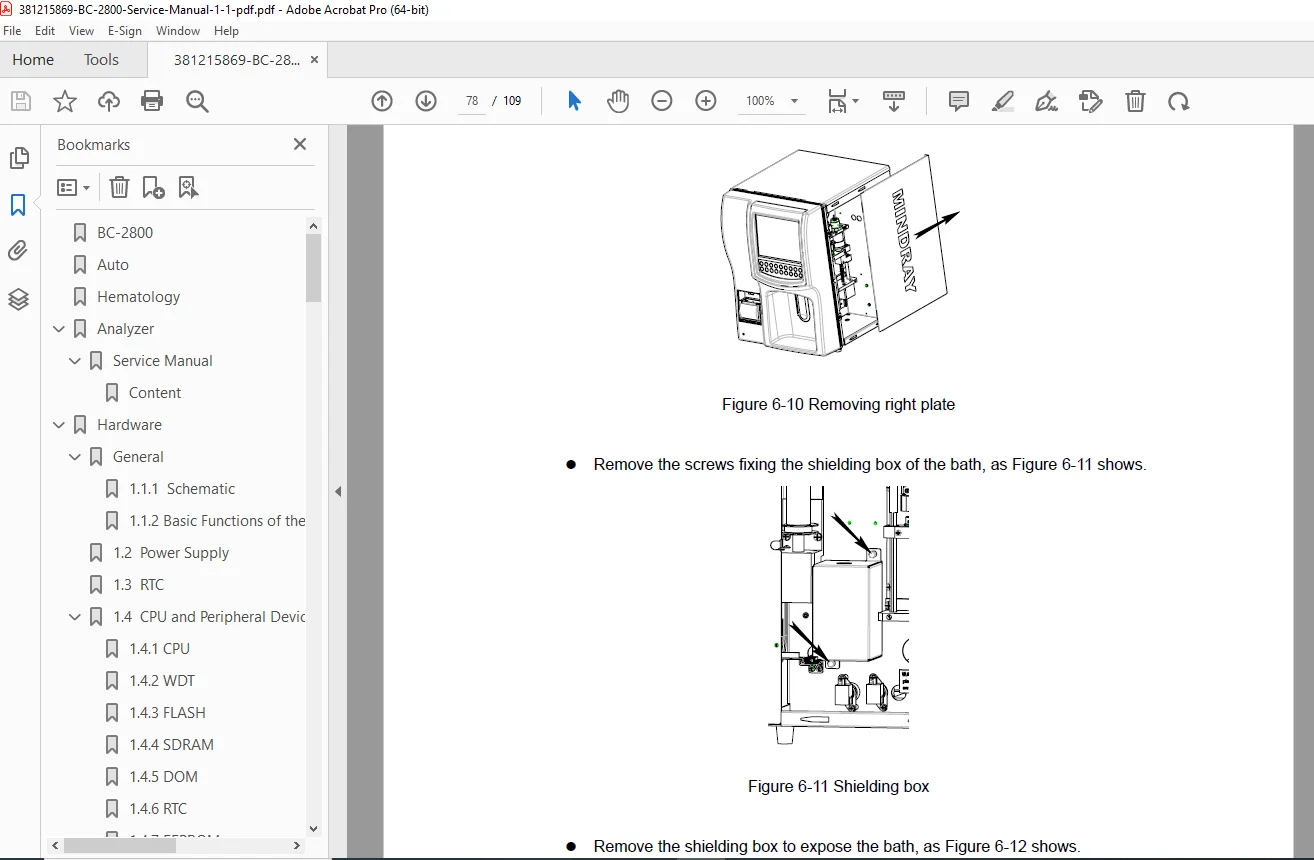
3.2 Disassembling the Main Unit
- Required tools and equipment
- Step-by-step disassembly procedures
- Safety precautions during disassembly
- Component removal sequences
- Proper handling of sensitive components
- Cable disconnection procedures
- Reassembly guidelines and notes
CHAPTER 4: HISTOGRAMS AND PULSE GRAPHS (Pages 4-1 to 4-3)
4.1 Histograms
- WBC histogram interpretation
- RBC histogram interpretation
- PLT histogram interpretation
- Normal distribution patterns
- Abnormal pattern recognition
- Flagging criteria
- Clinical significance of histogram shapes
4.2 Pulse Graphs
- Pulse height analysis
- Pulse width characteristics
- Signal quality assessment
- Noise level evaluation
- Aperture blockage detection
- Troubleshooting abnormal pulses
CHAPTER 5: ADJUSTMENT (Pages 5-1)
5.1 Gain Adjustment
- WBC gain adjustment procedure
- RBC gain adjustment procedure
- PLT gain adjustment procedure
- HGB calibration procedure
- Baseline adjustment
- Threshold setting procedures
- Verification testing
- Quality control after adjustment
- Required calibration materials
- Adjustment frequency recommendations
CHAPTER 6: MAINTENANCE (Pages 6-1 to 6-28)
6.1 Regular Maintenance
- Daily maintenance procedures
- Weekly maintenance tasks
- Monthly maintenance schedules
- Quarterly maintenance requirements
- Annual service procedures
- Preventive maintenance checklists
6.2 System Maintenance
- Fluidic System Maintenance:
- Cleaning procedures
- Reagent line flushing
- Valve replacement
- Pump maintenance
- Aperture cleaning and verification
- Waste system maintenance
- Optical System Maintenance:
- HGB LED inspection
- Optical pathway cleaning
- Detector maintenance
- Mechanical System Maintenance:
- Sample probe inspection
- Syringe assembly service
- Motor lubrication
- Belt tension adjustment
6.3 System Status
- Status monitoring screens
- Real-time system indicators
- Performance metrics
- Alert and alarm review
6.4 System Self-Test
- Automated diagnostic procedures
- Self-test execution steps
- Test result interpretation
- Pass/fail criteria
- Component verification tests
- System integrity checks
6.5 Log
- Event log review
- Error log analysis
- Maintenance log entries
- Calibration history
- Service record keeping
6.6 System Configuration
- Configuration parameter access
- Setting modification procedures
- Parameter backup procedures
- Factory default restoration
6.7 Printing Management
- Printer setup and configuration
- Report formatting options
- Print queue management
- Troubleshooting print issues
6.8 Adjusting Sample Probe and Replacing Probe Wipe
- Sample probe positioning adjustment
- Probe wipe replacement procedure
- Probe alignment verification
- Aspiration depth setting
- Probe tip inspection
CHAPTER 7: TROUBLESHOOTING (Pages 7-1 to 7-3)
7.1 Error Codes
- Complete error code listing
- Error message descriptions
- Error severity classifications
- System response to errors
7.2 Solutions
- Troubleshooting flowcharts
- Systematic diagnostic approach
- Common Problems and Solutions:
- Sample aspiration failures
- Count result errors
- Fluidic system blockages
- Electrical system faults
- Communication errors
- Hardware component failures
- Software errors
- Calibration drift issues
- Step-by-step repair procedures
- Component testing methods
- Verification after repair
CHAPTER 8: LIST OF SPARE PARTS (Pages 8-1)
- Complete spare parts catalog
- Part numbers and descriptions
- Recommended spare parts inventory
- Critical component identification
- Ordering information
- Parts replacement frequency
- Compatibility information
APPENDIX: BC-2800 ERROR MESSAGE
- Comprehensive error message reference
- Error code to message mapping
- Detailed error descriptions
- Recommended actions for each error
- Related system components
- Cross-reference to troubleshooting procedures
Technical Specifications Covered:
✓ Hardware Architecture – Complete CPU board, driving board, and peripheral schematics
✓ Power Systems – Dual power supply design, voltage conversion, distribution diagrams
✓ Processor Systems – Motorola MCF5307 CPU, memory systems, storage devices
✓ Control Systems – Motor control, valve/pump driving, position sensing
✓ Fluidic Systems – Complete hydraulic pathways, reagent handling, waste management
✓ Measurement Systems – WBC/RBC/PLT counting, HGB measurement, aperture technology
✓ Display Systems – LCD interface, brightness control, keypad scanning
✓ Diagnostic Tools – Self-test procedures, system status monitoring, error logging
✓ Calibration – Gain adjustment procedures for all parameters
✓ Maintenance – Preventive maintenance schedules, cleaning procedures
✓ Troubleshooting – Error codes, diagnostic flowcharts, repair procedures
✓ Parts Management – Complete spare parts listing with part numbers
Analyzer Capabilities:
The BC-2800 Auto Hematology Analyzer performs complete blood count (CBC) analysis including:
- WBC (White Blood Cell) Count with differential analysis
- RBC (Red Blood Cell) Count and indices
- PLT (Platelet) Count and parameters
- HGB (Hemoglobin) Concentration measurement
- Histogram Generation for WBC, RBC, and PLT populations
- Quality Flags for abnormal results
- Automated Sample Processing with minimal manual intervention
Who Needs This Manual:
- Biomedical Equipment Technicians (BMET) servicing hematology analyzers
- Clinical Laboratory Engineers maintaining laboratory equipment
- Hospital Engineering Departments supporting in-house equipment
- Medical Equipment Service Companies providing contract maintenance
- Laboratory Managers overseeing equipment maintenance programs
- Mindray Authorized Service Centers performing warranty repairs
- Technical Training Departments for technician education
- Quality Assurance Personnel verifying equipment performance
Manual Features:
- Factory-authorized service and repair procedures
- Detailed hardware component specifications
- Complete electrical schematics and block diagrams
- Fluidic system diagrams and flow paths
- Step-by-step disassembly and reassembly instructions
- Comprehensive troubleshooting flowcharts
- Error code reference with solutions
- Maintenance schedules and procedures
- Calibration and adjustment protocols
- Spare parts catalog with part numbers
- Safety warnings and precautions throughout
- Professional technical illustrations
- System architecture documentation
- Quality control procedures
Download this essential service manual immediately and gain access to complete factory-authorized repair and maintenance procedures for the Mindray BC-2800 Auto Hematology Analyzer. This manual provides the detailed technical information required to maintain optimal analyzer performance and ensure accurate patient results!