Mitsubishi Forklift FB25-35(C)N Trucks Service Manual – PDF DOWNLOAD
Original price was: $76.95.$45.95Current price is: $45.95.
Mitsubishi Forklift FB25-35(C)N Trucks Service Manual – PDF DOWNLOAD
Description
Mitsubishi Forklift FB25-35(C)N Trucks Service Manual – PDF DOWNLOAD
FILE DETAILS:
Mitsubishi Forklift FB25-35(C)N Trucks Service Manual – PDF DOWNLOAD
Format: PDF
Language: English
Brand: Mitsubishi
DESCRIPTION:
Mitsubishi Forklift FB25-35(C)N Trucks Service Manual – PDF DOWNLOAD
FOREWORD:
- This service manual is a guide for servicing lift trucks. The long productive life of your lift truck depends on regular and proper servicing, consistent with the instructions provided in this service manual. Before starting to test, repair or rebuild a lift truck, read the respective sections of this manual carefully and familiarize yourself with all of the components.
- The descriptions, illustrations and specifications contained in this manual are for lift trucks with serial numbers in effect at the time of printing. Trucks are constantly being developed. The graphic illustrations in this manual may differ slightly from the actual design of the truck. The manufacturer reserves the right to modify the design, equipment and technical features without prior notice and without any obligations. For your convenience, the instructions are grouped by systems as an easy reference. Unauthorized copying and lending of this material is strictly prohibited.
TABLE OF CONTENTS:
Mitsubishi Forklift FB25-35(C)N Trucks Service Manual – PDF DOWNLOAD
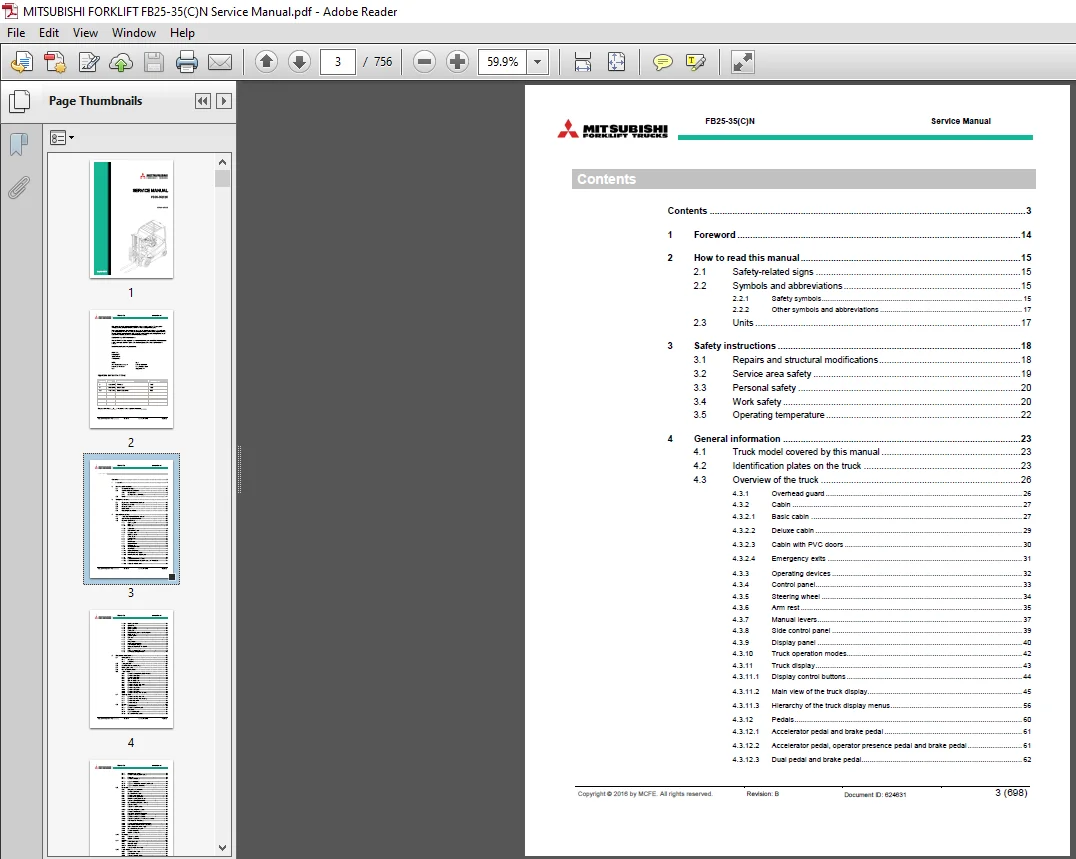
Contents 3
1 Foreword 14
2 How to read this manual 15
21 Safety-related signs 15
22 Symbols and abbreviations 15
221 Safety symbols 15
222 Other symbols and abbreviations 17
23 Units 17
3 Safety instructions 18
31 Repairs and structural modifications 18
32 Service area safety 19
33 Personal safety 20
34 Work safety 20
35 Operating temperature 22
4 General information 23
41 Truck model covered by this manual 23
42 Identification plates on the truck 23
43 Overview of the truck 26
431 Overhead guard 26
432 Cabin 27
4321 Basic cabin 27
4322 Deluxe cabin 29
4323 Cabin with PVC doors 30
4324 Emergency exits 31
433 Operating devices 32
434 Control panel 33
435 Steering wheel 34
436 Arm rest 35
437 Manual levers 37
438 Side control panel 39
439 Display panel 40
4310 Truck operation modes 42
4311 Truck display 43
43111 Display control buttons 44
43112 Main view of the truck display 45
43113 Hierarchy of the truck display menus 56
4312 Pedals 60
43121 Accelerator pedal and brake pedal 61
43122 Accelerator pedal, operator presence pedal and brake pedal 61
43123 Dual pedal and brake pedal 62
Copyright © 2016 by MCFE All rights reserved Revision: B Document ID: 624631 4 (698)
FB25-35(C)N Service Manual
43124 Pedal functionalities 63
4313 Operator’s seat 64
4314 Operating position 64
4315 Operating direction 67
4316 Drawbar pin 68
4317 Motor, hydraulic system and electrical system 69
4318 Electric panel 70
4319 Hydraulic system 71
4320 Drive axle 72
4321 Sensors 72
4322 Lifting carriage 76
4323 Integrated sideshift carriage 76
4324 Hook-on sideshift carriage 77
4325 Integrated fork positioner with sideshift 77
4326 Mast 78
4327 Overhead guard and load backrest 79
4328 Nominal capacity height indicator 80
5 Mechanical maintenance 82
51 Lifting points 82
511 Jack points 82
512 Hoist points 82
52 Transportation 83
53 Assembly and commissioning 84
54 Order spare parts 85
55 How to clean the truck 85
56 Truck covers 86
561 Remove the cover of the hydraulic valve block 88
562 Remove the pedal plate 88
563 Remove the floor plate 89
564 Open the battery door 90
565 Open the battery cover 91
566 Remove the back cover 92
567 Remove the steering wheel cover 93
568 Remove the control panel 93
569 Remove the step cover 94
5610 Remove the side plate 94
5611 Remove the cup holder 95
5612 Remove the steering wheel front cover 95
57 Steering wheel 96
571 Remove the steering wheel unit 96
572 Remove the steering wheel gas spring 97
573 Remove the lever unit 98
574 Remove the levers 99
58 Pedals 100
581 Accelerator pedal 100
5811 Remove the accelerator pedal 100
582 Brake pedal 101
5821 Adjust the brake pedal 101
5822 Disassemble the brake pedal 102
Copyright © 2016 by MCFE All rights reserved Revision: B Document ID: 624631 5 (698)
FB25-35(C)N Service Manual
583 Operator presence pedal 105
5831 Remove the operator presence pedal 105
584 Dual pedal 106
5841 Remove the dual pedal 107
5842 Adjust the dual pedal 109
5843 Adjust the center position sensor of the dual pedal 110
5844 Adjust the dual pedal angle sensor 111
59 Drive axle 112
591 Lifting points of the drive axle 114
592 Remove the drive axle 114
593 Disassemble the drive axle 116
594 Remove the transmission gear 117
595 Remove the helical gear stage 121
596 Maintain the parking brake actuator 128
5961 Release the parking brake actuator 128
5962 Disassemble the parking brake actuator 130
5963 Replace the O-ring 131
5964 Replace the seal of the piston 132
5965 Install the parking brake actuator 132
597 Remove the traction motors 134
598 Install the left and right traction motors 136
599 Replace the service brake actuator 138
5991 Remove the service brake actuator 138
5992 Replace the spare parts of the service brake actuator 138
5993 Install the service brake actuator 140
5910 Remove the brake discs and ball ramp actuator 142
5911 Install the brake discs and the ball ramp actuator 143
59111 Measure the clearance of the air-gap 145
5912 Disassemble the impulse gear 147
5913 Remove the breathers 149
5914 Lubricate the drive axle 152
510 Rear axle 153
5101 Replace the rear axle 154
5102 Lubricate the rear axle 156
511 Wheels 157
5111 Solid rubber wheels 157
5112 Pneumatic wheels 157
51121 Punctured wheel 158
5113 Before you replace the wheels 158
512 Front wheels 159
5121 Remove the front wheel 160
5122 Install the front wheel 161
5123 Replace the wheel shaft bolts 162
513 Rear wheels 167
5131 Remove the rear wheels 167
5132 Install the rear wheel 168
5133 Replace the wheel shaft bolts of the rear wheel 170
Copyright © 2016 by MCFE All rights reserved Revision: B Document ID: 624631 6 (698)
FB25-35(C)N Service Manual
514 Brakes 172
5141 Bleed the service brake 172
515 Mast 173
5151 Detailed construction 174
51511 Simplex mast 174
51512 Duplex mast with initial lift 175
51513 Triplex mast 176
5152 Maintenance of the mast 177
51521 Daily maintenance 177
51522 Monthly maintenance 177
51523 Annual maintenance (600 h) 177
5153 Lubricant recommendations 178
51531 Mast chains 178
51532 Mast channels 178
5154 Lifting carriage 179
51541 Remove the lifting carriage 179
51542 Adjust the rollers of the lifting carriage 182
51543 Replace the guidance rollers of the lifting carriage 183
51544 Replace the main rollers of the lifting carriage 183
51545 Replace the load backrest 184
5155 Remove the mast 184
5156 Disassemble the simplex mast 187
5157 Disassemble the duplex mast 191
5158 Disassemble the triplex mast 196
5159 Fork inspection 203
51510 Mast chains 207
515101 Inspect the mast chains 208
515102 Inspect the tension of the mast chains 215
515103 Adjust the mast chains 215
515104 Replace the mast chains 219
51511 Main rollers of the mast 221
515111 Replace the main rollers of the mast 222
51512 Free lift cylinder 223
515121 Replace the free lift cylinder 224
515122 Sealing housing of the free lift cylinder 227
51513 Side cylinders 228
515131 Replace the side cylinders 229
515132 Sealing housing of the side cylinder 231
51514 Tilt cylinders 233
515141 Remove the tilt cylinders 233
515142 Sealing housing of the tilt cylinder 235
515143 Lubrication points of the tilt cylinder 236
51515 Sideshift cylinder 237
515151 Remove the piston of the sideshift cylinder 237
515152 Sealing housing of the sideshift cylinder 238
Copyright © 2016 by MCFE All rights reserved Revision: B Document ID: 624631 7 (698)
FB25-35(C)N Service Manual
516 Hook-on sideshift 239
5161 Remove the hook-on sideshift frame 240
5162 Remove the hook-on sideshift cylinder piston 241
517 Operator’s seat 242
5171 MSG20 242
51711 Remove the operator’s seat from the truck 242
51712 Replace the paddings 243
51713 Replace the seat base 244
51714 Replace the weight adjustment handle 247
51716 Replace the seat rails 249
51717 Install the seat arm rest 251
51718 Ground the operator’s seat 253
5172 MSG65 254
51721 Remove the operator’s seat from the truck 254
51722 Replace the seat paddings 254
51723 Replace the seat base 256
51724 Replace the seat belt 258
51725 Replace the seat switch 260
51726 Replace the weight adjustment handle 262
51727 Replace the seat rails 263
51728 Replace the gas spring 264
51729 Install the hip guard 265
517210 Ground the operator’s seat 266
5173 MSG75 267
51731 Remove the operator’s seat from the truck 267
51732 Replace the seat paddings 267
51733 Replace the seat base 267
51734 Replace the seat belt 268
51735 Replace the seat switch 268
51736 Replace the weight adjustment handle 269
51737 Replace the gas spring 269
51738 Replace the compressor 269
51739 Replace the compressor tank 270
517310 Ground the operator’s seat 270
518 Manual holder 271
5181 Open the manual holder 271
5182 Replace the manual holder 272
519 Arm rest 273
5191 Remove the arm rest 273
5192 Open the arm rest 274
5193 Remove the arm rest levers 275
5194 Remove the thumb plate 276
5195 Replace the arm rest padding 276
520 Cabin 277
5201 Operator door 277
Copyright © 2016 by MCFE All rights reserved Revision: B Document ID: 624631 8 (698)
FB25-35(C)N Service Manual
52011 Open the operator door 277
52012 Replace the opening handle of the operator door 278
52013 Replace the lock of the operator door 280
52014 Replace the gas spring of the operator door 281
52015 Adjust the operator door 282
5202 Side door 285
52021 Replace the opening lever of the side door 285
52022 Replace the gas spring of the side door 286
5203 Open the roof cover 287
5204 Rear window 288
52041 Open the rear window 288
52042 Replace the gas spring 290
52043 Remove the rear window 290
5205 Windshield washer 291
52051 Replace the windshield wiper 292
52052 Remove the motor of the windshield wipers 292
52053 Windshield washer tank 294
5206 Cabin seals 295
5207 Sun guard 300
52071 Remove the sun guard 300
52072 Remove the sun guard frame 301
5208 Radio 302
52081 Remove the radio 303
5209 Reading light 304
52010 Heater 305
520101 Remove the heater 305
520102 Replace the air filter of the heater 306
6 Electrical operation 307
61 How to use the schematic diagram 307
62 Power source 310
63 Safety circuit (emergency stop button) 310
64 Key switch 310
65 Traction 311
7 Battery maintenance 312
71 Safety regulations concerning the handling of lead-acid batteries 313
72 Battery maintenance 314
721 Daily maintenance 314
722 Weekly maintenance 314
723 Monthly maintenance 314
724 Annual maintenance 315
725 General maintenance 315
726 Storage 315
727 Malfunctions 315
728 How to clean batteries 316
73 Requirements for battery charging areas 317
Copyright © 2016 by MCFE All rights reserved Revision: B Document ID: 624631 9 (698)
FB25-35(C)N Service Manual
74 Charge the battery 319
75 Measure the specific gravity of the battery 322
76 Replace the battery 322
761 Replace the battery with the standard equipment 323
762 Guide the battery cable 325
763 Battery sideway exchange 326
8 Electric system maintenance 327
81 Display panel 327
811 Emergency stop button 327
8111 Emergency stop button functionality check 328
812 Key switch 328
8121 Key switch functionality check 329
82 Electric panel 330
821 Discharge the controllers 331
822 Remove the electric panel 332
823 Vehicle controller 333
824 Vehicle controller connectors 333
8241 CNA external connector 334
8242 CNB external connector 336
825 Traction controller 338
826 Traction controller connectors 338
8261 CNA external connector 339
8262 Description of the power connections 342
827 Pump controller 343
828 Pump controller connectors 343
8281 CNA external connector 344
8282 Description of the power connections 345
829 Fuses 346
83 Motor compartment 348
831 Traction motor 349
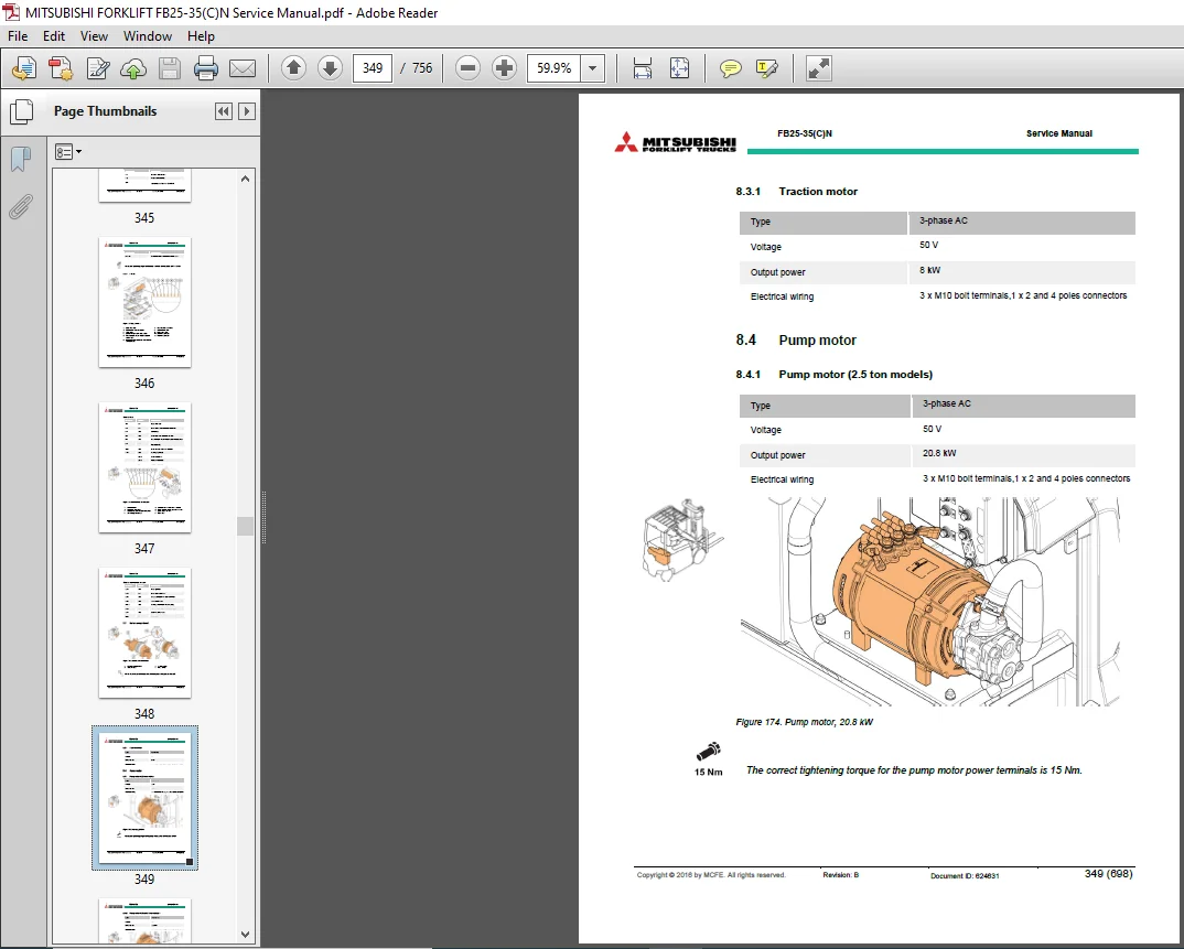
84 Pump motor 349
841 Pump motor (25 ton models) 349
842 Pump motor (30 and 35 ton models) 350
843 Remove the pump motor 350
844 Lubricate the pump axle splines 352
85 Sensors 353
851 Traction motor sensors 353
8511 Temperature sensor 353
8512 Rotation sensor 356
852 Pump motor sensors 358
8521 Temperature sensor 358
8522 Rotation sensor 359
853 Battery door sensor 360
8531 Functionality check of the battery door sensor 361
8532 Replace the battery door sensor 361
854 Pressure sensor 362
8541 Functionality check of the pressure sensor 363
Copyright © 2016 by MCFE All rights reserved Revision: B Document ID: 624631 10 (698)
FB25-35(C)N Service Manual
855 Rear axle sensor 364
8551 Functionality check of the rear axle sensor 364
8552 Replace the rear axle sensor 365
856 Parking brake sensor 366
8561 Functionality check of the parking brake sensor 367
857 Steering wheel sensor 367
8571 Functionality check of the steering wheel sensor 368
858 Accelerator pedal sensor 368
8581 Functionality check of the accelerator pedal 369
859 Brake pedal sensor 370
8591 Functionality check of the brake pedal sensor 370
8510 Operator presence pedal sensor 371
85101 Functionality check of the operator presence pedal 371
8511 Dual pedal sensors 372
85111 Angle sensor 372
85112 Functionality check of the angle sensor 373
85113 Center position sensor 374
8512 Lift/lower lever sensor, manual levers 375
85121 Functionality check of the lift/lower lever sensor 375
8513 Seat belt switch 376
85131 Functionality check of the seat belt switch 376
8514 Seat switch 377
85141 Functionality check of the seat switch 377
8515 Switches of the side control panel 378
8516 Manual control switches 379
8517 Stop light switch 381
8518 Driving direction selection switch 381
85181 Functionality check of the driving direction selection switch 382
8519 Horn switch 383
9 Electric system adjustments and measurements 385
91 Calibrate the arm rest levers 385
92 Insulation resistance test 385
921 Test voltage 385
922 Checking the insulation tester 385
923 Measure the insulation resistance 386
9231 Insulation resistance of the truck 386
9232 Insulation resistance of the battery 387
10 Hydraulic operation 388
101 Hydraulic symbols 392
102 Hydraulic oil recommendations 395
103 Hydraulics with fingertip controls 396
104 Hydraulics with manual levers 397
105 Hydraulic valve unit with fingertip controls 397
1051 Valve M1, M2, M3, M4, M5, M6, M7 and M8 400
1052 Valve M9 and M10 401
1053 Emergency lowering valve 401
Copyright © 2016 by MCFE All rights reserved Revision: B Document ID: 624631 11 (698)
FB25-35(C)N Service Manual
1054 PDS valve 401
1055 Clamp release valve 402
106 Hydraulic valve unit with manual levers 403
1061 Emergency lowering valve 405
107 Hydraulic system 406
108 Hydraulics with additional hydraulic functions 407
1081 Additional hydraulic functions in a truck with the arm rest 407
10811 Hydraulics with 4 section control valve 407
10812 Hydraulics with 4 section control valve 407
1082 Additional hydraulic functions in a truck with the manual levers 408
10821 Hydraulics with the 3 section control valve and the reel clamp 408
10822 Hydraulics with the 4 section control valve 408
10823 Hydraulics with the 5 section control valve 409
109 Hydraulic system maintenance 410
1091 Remove the hydraulic oil suction filter 410
1092 Clean the oil tank 412
1093 Replace the hydraulic oil return filter 413
1094 Replace the air breather filter 415
1095 Set the lifting pressure 415
1096 Disassemble the valves 417
1097 Remove the 4/5 auxiliary function selection valve block 418
1098 Remove the clamp release valve 419
1099 Remove the PDS valve 419
10910 Remove the auxiliary function pressure limit valve 420
109101 Adjust the auxiliary function pressure limit valve 421
11 TruckTool Diagnostics 422
111 Location of the service socket 423
1111 Remove the service socket cover 423
12 Parameter descriptions 424
121 VCM master 424
122 Traction controller 435
123 Pump controller 435
13 Alarm codes 436
131 VCM 437
1311 VCM master alarms 437
1312 VCM slave alarms 463
132 Traction controller 480
1321 Traction controller right master alarms 480
1322 Traction controller right slave alarms 505
1323 Traction controller left master alarms 518
1324 Traction controller left slave alarms 550
133 Pump controller 563
1331 Pump controller master alarms 563
1332 Pump controller slave alarms 590
134 Arm rest alarms 600
135 Truck display alarms 610
Copyright © 2016 by MCFE All rights reserved Revision: B Document ID: 624631 12 (698)
FB25-35(C)N Service Manual
14 Service data 613
141 Special tightening torques 613
142 Tightening torque for standard bolts and nuts 613
143 Maintenance check list 615
144 Lubrication 620
1441 Hydraulic oil 620
1442 Transmission oil 620
1443 Brake oil 620
1444 Lubrication points 621
1445 Rear axle 621
1446 Mast chains 621
1447 Mast channels 621
1448 Pump axle splines 621
145 Special tools 621
15 Options 625
151 Accessory clamp 626
152 A4 paper holder 627
153 Smart backup alarm 629
154 Road light kit 632
1541 Turn signals 634
1542 Brake lights 634
1543 Front lights 636
155 Amber strobe 637
156 Automatic working lights 640
157 Blue spot rear light 642
158 DC-DC converter 645
1581 Install the DC-DC converter 645
159 12 V connector 646
1510 Automated performance reduction based on lift height 647
1511 Tilt angle sensor / display status indication with FC 651
1512 Load weight indicator and overload warning system 654
1513 Operator’s seat options and accessories 656
15131 Arm rest 656
15132 Backrest extension for MSG65 660
151321 Install the mounting bracket of the backrest extension 660
151322 Backrest extension adjustment 660
1514 Fire extinguisher 661
1515 Battery sideway exchange tools 662
15151 Requirements for power pallet trucks used to move batteries of
counterbalance trucks 662
15152 Installation of the battery sideway exchange tool 663
15153 Replace the battery with the battery sideway exchange tools 664
15154 Guide the battery cable 669
15155 Disassemble the battery locking mechanism 669
1516 Rear view mirror 670
1517 External rear view mirrors 672
Copyright © 2016 by MCFE All rights reserved Revision: B Document ID: 624631 13 (698)
FB25-35(C)N Service Manual
1518 Wide view mirror 673
1519 Dead angle mirror overview 675
1520 Hydraulic accumulator 676
1521 Wide thread fenders 677
1522 Abbot 2 678
16 Technical specification 680
161 FB25N, FB25CN, FB30N, FB30CN and FB35N 681
17 Index 685
APPENDIX A: Stickers 690
MITSUBISHI FORKLIFT FB25-35(C)N TRUCKS SERVICE MANUAL – PDF DOWNLOAD:
IMAGES PREVIEW OF THE MANUAL:
PLEASE NOTE:
- This is the SAME exact manual used by your dealers to fix your vehicle.
- The same can be yours in the next 2-3 mins as you will be directed to the download page immediately after paying for the manual.
- Any queries / doubts regarding your purchase, please feel free to contact [email protected]