Mitsubishi Forklift FD100N1 FD120N1 FD135N1 FD150AN1 FD160AN1 Service Manual – PDF DOWNLOAD
Original price was: $43.95.$26.95Current price is: $26.95.
Mitsubishi Forklift FD100N1 FD120N1 FD135N1 FD150AN1 FD160AN1 Service Manual – PDF DOWNLOAD
For use with 1204E Diesel Engine Service Manual
Pub.No : 99799-50100
FD100N1 AF15E-00011-up
FD120N1 AF15E-00011-up
FD135N1 AF15E-00011-up
FD150AN1 AF24C-00011-up
FD160AN1 AF39A-00011-up
Description
Mitsubishi Forklift FD100N1 FD120N1 FD135N1 FD150AN1 FD160AN1 Service Manual – PDF DOWNLOAD
FILE DETAILS:
Mitsubishi Forklift FD100N1 FD120N1 FD135N1 FD150AN1 FD160AN1 Service Manual – PDF DOWNLOAD
Format: PDF
Language: English
Brand: Mitsubishi
DESCRIPTION:
Mitsubishi Forklift FD100N1 FD120N1 FD135N1 FD150AN1 FD160AN1 Service Manual – PDF DOWNLOAD
For use with 1204E Diesel Engine Service Manual
Pub.No : 99799-50100
FD100N1 AF15E-00011-up
FD120N1 AF15E-00011-up
FD135N1 AF15E-00011-up
FD150AN1 AF24C-00011-up
FD160AN1 AF39A-00011-up
FOREWORD :
This service manual is a guide for servicing Mitsubishi forklift trucks. The long productive life of your forklift truck(s) depends on regular and proper servicing consistent with what you will learn by reading this service manual. Read the respective sections of this manual carefully and familiarize yourself with all of the components before attempting to start a test, repair, or rebuild the forklift truck. The descriptions, illustrations, and specifications contained in this manual are for forklift trucks with serial numbers in effect at the time of printing. Mitsubishi Forklift Trucks reserves the right to change specifications or designs without notice and without incurring obligations. For your convenience the instructions are grouped by systems as an easy reference.
SAFETY:
The proper safe lubrication and maintenance for these lift trucks, recommended by Cat Lift Trucks, are outlined in the SERVICE MANUAL. Read and understand the SERVICE MANUAL before performing any lubrication or maintenance on these lift trucks. Improper performance of lubrication or maintenance procedures is dangerous and could result in injury or death. The serviceman or mechanic may be unfamiliar with many of the systems on this forklift truck. This makes it important to use caution when performing service work. – DO NOT operate these lift trucks unless you have read and understood the instructions in the SERVICE MANUAL.
Improper forklift truck operation is dangerous and could result in injury or death. A knowledge of the system and/or components is important before the removal or disassembly of any component. Because of the size of some of the forklift truck components, the serviceman or mechanic should check the weights noted in this manual. Use proper lifting procedures when removing any components. The following is a list of basic precautions that should always be observed:
TABLE OF CONTENTS:
Mitsubishi Forklift FD100N1 FD120N1 FD135N1 FD150AN1 FD160AN1 Service Manual – PDF DOWNLOAD
Chapter 1 GENERAL INFORMATION
1 Model View 1-1
2 Applicable Forklift Truck Models 1-1
3 Serial Number Locations 1-2
4 Specifications 1-3
4 1 Dimensions 1-4
4 2 Performance 1-5
Chapter 2 COOLING SYSTEM
1 Specifications 2-1
2 Structure 2-2
3 Removing Cooling System 2-3
3 1 Preparation 2-3
3 2 Removal Sequence of Expansion Tank and Radiator 2-3
3 3 Removal Sequence of Intercooler and Oil Cooler 2-4
3 4 Removal Sequence of Cooling Fan 2-5
3 5 Suggestions for Removal 2-6
4 Inspecting and Adjusting Radiator and Intercooler 2-7
4 1 Intercooler 2-7
4 2 Inspecting Fan Belt 2-7
4 3 Radiator 2-7
4 4 Antifreeze and Cooling Water 2-8
5 Installing Cooling System 2-9
5 1 Suggestions for Installation 2-9
6 Troubleshooting 2-13
7 Service Data 2-14
7 1 Fan Belt 2-14
7 2 Radiator 2-14
7 3 Expansion Tank 2-15
7 4 Intercooler 2-16
7 5 Oil Cooler 2-17
Chapter 3 ELECTRICAL SYSTEM
1 Chassis Electrical Components and Wiring Outline 3-1
1 1 Electrical Components and Wiring Diagram of Each System 3-2
2 Console Box 3-15
2 1 Outline of Console Box 3-15
2 2 Removing Meter Panel 3-15
2 3 Installing Meter Panel 3-16
3 Main Electrical Components 3-17
3 1 Meter Panel 3-17
3 2 Select Switch 3-18
3 3 Brake Warning Icon 3-19
3 4 Key Switch (Anti-Restart Switch) 3-20
TABLE OF CONTENTS
TOC-2
3 5 Light Switch and Turn Signal Switch 3-21
3 6 Direction (FNR) Switch 3-23
3 7 Horn 3-24
3 8 Fuel Tank Unit 3-25
3 9 Stop Light Switch 3-25
3 10 Thermo Switch (T/C Oil) 3-26
3 11 Speed Sensor 3-27
3 12 Fuse Box 3-28
3 13 Relay Box 3-29
3 14 Adjusting Procedure for Accelerator Pedal 3-31
3 15 Low Air Pressure Switch 3-31
3 16 List of Lights 3-32
4 Battery and Maintenance 3-33
4 1 Battery Specific Gravity Condition and Adjustment 3-33
4 2 Relationship Between Electrolyte Specific Gravity and State of Charge 3-34
4 3 Precautions for Battery Charging 3-34
5 Meter panel 3-35
5 1 Meter Panel Layout 3-35
5 2 Basic Display 3-37
5 3 Basic Operation 3-42
5 4 When a Warning Occurs 3-50
5 5 When Several Warnings Occur Simultaneously 3-52
5 6 Warning Symbols 3-53
5 7 Warning Icons 3-54
5 8 Optional Features 3-55
5 9 Hour Meter 3-58
5 10 Troubleshooting 3-59
6 Wire Color 3-60
6 1 List of Wire Color Codes 3-60
7 Troubleshooting 3-61
7 1 Engine Startup Problem 3-61
7 2 Gauge-Related Problems 3-61
7 3 Light-Related Problems 3-62
7 4 Warning Device Problems 3-63
7 5 Battery-Related Problems 3-64
Chapter 4 CONTROLLERS
1 Outline 4-1
1 1 System Configuration 4-1
1 2 Color Coding 4-3
1 3 Controller External View 4-4
2 Service Tool Functions 4-17
2 1 Menu Structure 4-17
2 2 Input Monitor and Output Monitor 4-18
2 3 Truck Status 4-23
2 4 Truck History 4-24
3 Diagnostic Code List 4-25
4 Troubleshooting 4-27
TABLE OF CONTENTS
TOC-3
4 1 General Precautions 4-27
4 2 VCM-7 Memory Check Warning (F01) 4-29
4 3 VCM-7 Battery Voltage Warning (F02) 4-30
4 4 VCM-7 Communication Warning (F03) 4-32
4 5 Meter Panel Communication Warning (F07) 4-34
4 6 Lift Lever Neutral Warning (F10) 4-35
4 7 Tilt Lever Neutral Warning (F11) 4-37
4 8 Attachment 1 Lever Neutral Warning (F12) 4-39
4 9 Attachment 2 Lever Neutral Warning (F13) 4-41
4 10 Attachment 3 Lever Neutral Warning (F14) 4-43
4 11 ECM Communication Warning (F15) 4-45
4 12 Direction Lever Warning (F16) 4-47
4 13 Vehicle Speed Warning (F17) 4-48
4 14 Lift Lever Warning (F20) 4-49
4 15 Tilt Lever Warning (F22) 4-51
4 16 Attachment 1 Lever Warning (F24) 4-53
4 17 Attachment 2 Lever Warning (F26) 4-55
4 18 Attachment 3 Lever Warning (F28) 4-57
4 19 Joystick Duplicate Warning (F29) 4-59
4 20 Vehicle Speed Sensor Warning (F34) 4-61
4 21 Output Unit Warning (F41) 4-62
4 22 Output Unit Supply Voltage Warning (F44) 4-63
4 23 Output Unit Communication Warning (F45) 4-65
4 24 Input Unit Warning (F46) 4-67
4 25 Input Unit Communication Warning (F49) 4-68
4 26 Lift up Solenoid Warning (F50) 4-70
4 27 Lift Down Solenoid Warning (F52) 4-72
4 28 Lift Solenoid Leak (F54) 4-74
4 29 Tilt Forward Solenoid Warning (F55) 4-77
4 30 Tilt Backward Solenoid Warning (F57) 4-79
4 31 Tilt Solenoid Leak (F59) 4-81
4 32 Attachment 1A Solenoid Warning (F60) 4-84
4 33 Attachment 1B Solenoid Warning (F62) 4-86
4 34 Attachment 1 Solenoid Leak (F64) 4-88
4 35 Attachment 2A Solenoid Warning (F65) 4-91
4 36 Attachment 2B Solenoid Warning (F67) 4-93
4 37 Attachment 2 Solenoid Leak (F69) 4-95
4 38 Attachment 3A Solenoid Warning (F70) 4-98
4 39 Attachment 3B Solenoid Warning (F72) 4-100
4 40 Attachment 3 Solenoid Leak (F74) 4-102
4 41 Unload Solenoid Warning (F75) 4-105
4 42 Unload Solenoid Leak (F79) 4-107
4 43 Transmission Forward Solenoid Warning (F85) 4-109
4 44 Transmission Reverse Solenoid Warning (F87) 4-111
4 45 Transmission Solenoid Leak (F89) 4-113
4 46 VCM-7 Speed Change Solenoid 1 Warning (F93) 4-115
4 47 VCM-7 Speed Change Solenoid 2 Warning (F94) 4-117
4 48 VCM-7 Speed Change Solenoid Leak (F95) 4-119
4 49 VCM-7 Setting Warning (F96) 4-121
TABLE OF CONTENTS
TOC-4
Chapter 5 POWER TRAIN
1 Specifications 5-1
2 Structure 5-2
3 Reduction Ratio 5-3
4 Removing and Installing Engine and Transmission Unit 5-4
4 1 Preparation 5-4
4 2 Removing Overhead Guard, Covers, and Air Cleaner Element 5-5
4 3 Removing Harnesses 5-6
4 4 Disconnecting Pipes and Hoses 5-7
4 5 Preparation for Removing Engine and Transmission Unit 5-9
4 6 Removing Engine and Transmission Unit 5-10
5 Installing Engine and Transmission Unit 5-11
5 1 Suggestions for Installation 5-11
5 2 Capacity and Brand of Oils and Cooling Water 5-13
Chapter 6 3-SPEED POWERSHIFT TRANSMISSION
1 Specifications 6-1
2 Structure 6-2
2 1 Torque Converter 6-2
2 2 Transmission 6-3
2 3 Power Flow – Forward 6-4
2 4 Power Flow – Reverse 6-5
2 5 Control Valve 6-6
2 6 Main Regulator Valve 6-6
2 7 3 Speed Transmission Hydraulic Lines 6-7
2 8 Automatic 3 Speed Shift Mechanism 6-9
2 9 Torque Converter Drive Control 6-10
3 Removing Transmission 6-11
3 1 Removing Torque Converter 6-11
4 Installing Transmission 6-12
5 Disassembling Torque Converter 6-13
5 1 Disassembly Sequence 6-13
5 2 Suggestions for Disassembly 6-13
6 Inspecting and Repairing Torque Converter 6-14
7 Assembling Torque Converter 6-17
7 1 Assembly Sequence 6-17
7 2 Suggestions for Assembling Torque Converter 6-18
8 Disassembling Transmission 6-19
8 1 Disassembly Sequence of Control Valve and External Parts 6-19
8 2 Disassembling Transmission Cover and Output, 1st/3rd Clutch, Forward Clutch,
Reverse Clutch, and Input Shafts 6-20
8 3 Suggestions for Disassembling Transmission 6-21
8 4 Disassembly Sequence of Stator Shaft and Oil Pump 6-23
8 5 Suggestions for Disassembling Oil Pump 6-24
8 6 Disassembly Sequence of Forward Clutch Shaft Assembly 6-26
TABLE OF CONTENTS
TOC-5
8 7 Suggestions for Disassembling Forward Clutch Shaft Assembly 6-27
8 8 Disassembly Sequence of 1st/3rd Speed Clutch Shaft Assembly 6-28
8 9 Suggestions for Disassembling 1st/3rd Clutch Shaft Assembly 6-28
8 10 Disassembly Sequence of Reverse Clutch Shaft Assembly 6-29
8 11 Suggestions for Disassembling Reverse Clutch Shaft Assembly 6-29
9 Inspecting and Repairing Transmission 6-30
10 Assembling Transmission 6-33
10 1 Assembly Sequence of Forward Clutch Assembly
(1st/3rd Clutch Shaft Assembly) (Reverse Clutch Shaft Assembly) 6-33
10 2 Suggestions for Assembling Forward Clutch Assembly
(1st/3rd Clutch Shaft Assembly) (Reverse Clutch Shaft Assembly) 6-34
10 3 Assembly Sequence of Stator Shaft and Oil Pump 6-35
10 4 Suggestions for Assembling Stator Shaft and Oil Pump 6-36
10 5 Assembly Sequence of Input Shaft, Forward Clutch, 1st/3rd Speed Clutch,
Reverse Clutch, Output Shafts, and Transmission Cover 6-37
10 6 Suggestions for Assembling Input Shaft, Forward Clutch, 1st/3rd Speed Clutch,
Reverse Clutch, Output Shafts, and Transmission Cover 6-38
10 7 Assembly Sequence of Control Valve and External Parts 6-40
11 Disassembling Control Valve 6-41
11 1 Disassembly Sequence 6-41
12 Inspecting and Repairing Control Valve 6-42
13 Assembling Control Valve 6-43
13 1 Preparation 6-43
13 2 Assembly Sequence 6-43
13 3 Suggestions for Assembling Control Valve 6-43
14 Disassembling Main Regulator Valve 6-44
14 1 Disassembly Sequence 6-44
15 Inspecting and Repairing Main Regulator Valve 6-44
16 Assembling Main Regulator Valve 6-44
16 1 Suggestions for Assembly 6-44
17 Adjustment 6-45
17 1 Adjusting Brake Pedal and Inching Pedal 6-45
17 2 Checking Oil Pressure 6-47
17 3 Stall Speed Measurement 6-50
17 4 10 m Start Acceleration Test 6-50
17 5 Testing Automatic 3 Speed Transmission Functions 6-51
18 Troubleshooting 6-52
19 Service Data 6-57
19 1 Stall Speed and Oil Pressure 6-57
19 2 Pump Boss 6-57
19 3 Pilot Boss 6-58
19 4 Oil Pump 6-58
19 5 Stator 6-59
19 6 Flexible Plate 6-60
19 7 Clutches 6-61
19 8 Input Shaft, Forward, Reverse, and 1st/ 3rd Speed Clutch Shafts, and Servo Case
6-62
19 9 Backlash of Gears 6-63
TABLE OF CONTENTS
TOC-6
19 10 Control Valve 6-64
19 11 Main Regulator Valve 6-65
19 12 Inching Pedal Control 6-65
Chapter 7 FRONT AXLE AND REDUCTION DIFFERENTIAL
1 Specifications 7-1
2 Structure 7-2
2 1 General Description (FD100N1 to FD150AN1) 7-2
2 2 General Description (FD160AN1) 7-4
2 3 Reduction Differential 7-8
3 Removing Front Wheels 7-9
3 1 Preparation 7-9
3 2 Removal Sequence 7-9
3 3 Suggestions for Removal 7-10
4 Installing Front Wheels 7-11
4 1 Suggestions for Installation 7-11
5 Removing Front Axle and Reduction Differential 7-12
5 1 Preparation 7-12
5 2 Removal Sequence 7-13
5 3 Suggestions for Removal 7-14
6 Installing Front Axle and Reduction Differential 7-15
6 1 Suggestions for Installation 7-15
7 Removing Reduction Differential 7-16
7 1 Preparation 7-16
7 2 Removal Sequence 7-16
7 3 Suggestions for Removal 7-16
8 Installing Reduction Differential 7-17
8 1 Suggestions for Installation 7-17
9 Disassembling Hub Reduction (FD100N1 to FD150AN1) 7-17
9 1 Preparation (On-Truck Condition) 7-17
9 2 Disassembly Sequence of Hub Reduction 7-17
9 3 Suggestions for Disassembling Hub Reduction 7-19
9 4 Disassembly Sequence of Wheel Brake 7-20
9 5 Suggestions for Disassembling Wheel Brake 7-20
10 Inspecting and Repairing Hub Reduction (FD100N1 to FD150AN1) 7-21
10 1 Assembly Sequence of Wheel Brake 7-23
10 2 Suggestions for Assembling Wheel Brake 7-23
10 3 Assembly Sequence of Hub Reduction 7-24
10 4 Suggestions for Assembling Hub Reduction 7-25
11 Disassembling Hub Reduction (FD160AN1) 7-27
11 1 Disassembly Sequence of Hub Reduction 7-27
11 2 Suggestions for Disassembling Hub Reduction 7-28
11 3 Disassembly Sequence of Wheel Brake 7-30
12 Inspecting and Repairing Hub Reduction (FD160AN1) 7-31
12 1 Assembly Sequence of Wheel Brake 7-33
12 2 Suggestions for Assembling Wheel Brake 7-33
TABLE OF CONTENTS
TOC-7
12 3 Assembly Sequence of Plates in Wheel Brake and Brake Cover 7-34
12 4 Suggestions for Assembling Plates in Wheel Brake and Brake Cover 7-35
12 5 Assembly Sequence of Hub Reduction 7-36
12 6 Suggestions for Assembling Hub Reduction Assembly 7-37
13 Disassembling Reduction Differential 7-42
13 1 Preparation 7-42
13 2 Disassembly Sequence of Differential Gear Assembly 7-43
13 3 Suggestions for Disassembling Differential Gear Assembly 7-43
13 4 Disassembly Sequence of Reduction and Parking Brake Assembly 7-44
13 5 Suggestions for Disassembling Reduction and Parking Brake Assembly 7-44
13 6 Inspecting and Repairing Reduction and Parking Brake Assembly 7-45
14 Assembling Reduction Differential 7-47
14 1 Assembly Sequence of Differential Gear Assembly 7-47
14 2 Suggestions for Assembling Differential Gear Assembly 7-48
14 3 Adjusting Preload of Reduction Pinion 7-50
14 4 Adjusting the Contact Between Gear and Pinion Teeth 7-52
14 5 Assembly Sequence of Reduction and Parking Brake Assembly 7-56
14 6 Assembling Reduction and Parking Brake Assembly 7-57
14 7 Assembly Sequence of Reduction Differential 7-58
14 8 Suggestions for Assembling Reduction Differential 7-58
15 Troubleshooting 7-59
16 Service Data 7-60
16 1 Front Axle (FD100N1 to FD150AN1) 7-60
16 2 Front Axle (FD160AN1) 7-61
16 3 Reduction Differential 7-64
Chapter 8 REAR AXLE
1 Specifications 8-1
2 Structure 8-2
2 1 Rear Axle 8-2
2 2 Power Steering Cylinder 8-3
3 Removing Rear Wheel 8-4
3 1 Preparation 8-4
3 2 Removal Sequence 8-5
3 3 Suggestions for Removal 8-6
4 Installing Rear Wheel 8-6
4 1 Suggestions for Installation 8-6
5 Removing Rear Axle 8-7
5 1 Preparation 8-7
5 2 Removal Sequence 8-7
6 Installing Rear Axle 8-9
6 1 Suggestions for Installation 8-9
7 Disassembling Rear Axle Assembly 8-10
7 1 Disassembly Sequence 8-10
7 2 Suggestions for Removal 8-11
8 Assembling Rear Axle 8-13
TABLE OF CONTENTS
TOC-8
8 1 Assembly Sequence 8-13
9 Disassembling Power Steering Cylinder 8-18
9 1 Disassembly Sequence 8-18
9 2 Suggestions for Disassembly 8-19
10 Inspecting and Adjusting Power Steering Cylinder 8-20
11 Assembling Power Steering Cylinder 8-21
11 1 Assembly Sequence 8-21
11 2 Suggestions for Assembly 8-21
12 Adjustment 8-23
12 1 Measuring Minimum Turning Radius 8-23
13 Troubleshooting 8-25
14 Service Data 8-26
14 1 Rear Axle 8-26
14 2 Power Steering Cylinder 8-27
Chapter 9 BRAKE SYSTEM
1 Specifications 9-1
1 1 Dry Brake System 9-1
1 2 Wet Brake System 9-1
2 Structure 9-2
2 1 Outline of Wheel Brake System (Dry Brake System) 9-2
2 2 Outline of Wheel Brake System (Wet Brake System) 9-3
2 3 Structure of Oil Cooled Braking System 9-4
2 4 Air Dryer 9-5
2 5 Relay Valve 9-8
2 6 Brake Control Valve 9-10
2 7 Air Master (Dry Brake System) 9-11
2 8 Booster (Wet Brake System) 9-14
2 9 Wheel Brake (Dry Brake System) 9-16
2 10 Parking Brake System 9-17
2 11 Parking Brake Lever 9-18
2 12 Parking Brake 9-19
3 Removing Wheel Brake 9-20
3 1 Preparation 9-20
3 2 Removal Sequence (Dry Brake System) 9-20
3 3 Suggestions for Removal (Dry Brake System) 9-21
4 Installing Wheel Brake 9-23
4 1 Suggestions for Installation (Dry Brake System) 9-23
5 Disassembling Wheel Brake (Dry Brake System) 9-24
5 1 Disassembly Sequence 9-24
5 2 Suggestions for Disassembly 9-25
6 Inspecting and Repairing Wheel Brake (Dry Brake System) 9-26
7 Assembling Wheel Brake (Dry Brake System) 9-27
7 1 Assembly Sequence 9-27
7 2 Suggestions for Assembly 9-28
8 Disassembling Wheel Cylinder (Dry Brake System) 9-30
TABLE OF CONTENTS
TOC-9
8 1 Disassembly Sequence 9-30
9 Inspecting and Repairing Wheel Cylinder (Dry Brake System) 9-31
10 Assembling Wheel Cylinder 9-31
10 1 Suggestions for Assembly 9-31
11 Disassembling Air Master (Dry Brake System) 9-32
11 1 Disassembly Sequence 9-32
11 2 Suggestions for Disassembly 9-32
12 Assembling Air Master (Dry Brake System) 9-33
12 1 Suggestions for Assembly 9-33
13 Disassembling Booster (Wet Brake System) 9-34
13 1 Disassembly Sequence 9-34
13 2 Suggestions for Disassembly 9-35
14 Assembling Booster (Dry Brake System) 9-36
14 1 Suggestions for Assembly 9-36
15 Disassembling Parking Brake 9-37
15 1 Disassembly Sequence 9-37
16 Inspecting and Repairing Parking Brake 9-38
17 Assembling Parking Brake 9-38
17 1 Suggestions for Assembly 9-38
18 Disassembling Brake Control Valve 9-39
18 1 Disassembly Sequence 9-39
19 Assembling Brake Control Valve 9-40
19 1 Suggestions for Assembly 9-40
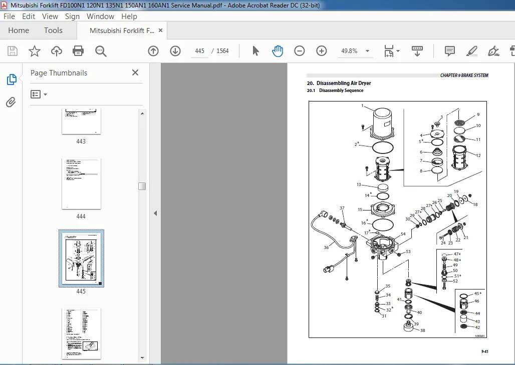
20 Disassembling Air Dryer 9-41
20 1 Disassembly Sequence 9-41
21 Inspecting and Repairing Air Dryer 9-42
21 1 Scheduled Inspection of Air Dryer 9-42
21 2 Inspecting and Adjusting Air Dryer After Assembly 9-43
22 Assembling Air Dryer 9-45
22 1 Suggestions for Assembly 9-45
23 Adjusting and Testing Actuation 9-48
23 1 Inspecting Wheel Brake 9-48
23 2 Inspecting Booster (Wet Brake System) 9-49
23 3 Bleeding Brake System 9-49
23 4 Bleeding Brake Pedal 9-50
23 5 Inspecting Brake Control Valve 9-50
23 6 Adjusting Parking Brake 9-51
23 7 Replacing Brake Cooling Oil 9-52
23 8 Flushing Brake Cooling Oil System 9-55
24 Troubleshooting 9-56
24 1 Wheel Brake 9-56
24 2 Parking Brake 9-57
24 3 Air Dryer 9-57
25 Service Data 9-58
25 1 Brake Pedal 9-58
25 2 Brake Control Valve 9-58
TABLE OF CONTENTS
TOC-10
25 3 Air Master (Dry Brake System) 9-59
25 4 Booster (Wet Brake System) 9-61
25 5 Wheel Brake (Dry Brake System) 9-62
25 6 Wheel Cylinder (Dry Brake System) 9-63
25 7 Parking Brake Lever 9-63
25 8 Parking Brake Drum 9-64
25 9 Air Dryer 9-65
Chapter 10 STEERING SYSTEM
1 Specifications 10-1
2 Structure 10-1
2 1 Steering System 10-1
2 2 Steering Valve 10-4
2 3 Steering Column 10-6
3 Removing and Installing Steering Valve Piping 10-8
3 1 Main Components 10-8
3 2 Suggestions for Disassembly and Assembly 10-9
4 Removing and Installing Steering Wheel, Steering Valve, and Tilt Lock
Lever 10-10
4 1 Removing Steering Wheel 10-12
4 2 Installing Steering Wheel 10-12
4 3 Inspecting Steering Wheel After Installation 10-16
4 4 Removing Steering Valve 10-16
4 5 Installing Steering Wheel 10-17
4 6 Disassembling Tilt Lock Lever 10-17
4 7 Assembling Tilt Lock Lever 10-18
5 Disassembling Steering Valve 10-19
5 1 Disassembly Sequence 10-19
5 2 Suggestions for Disassembling Steering Valve 10-20
5 3 Inspecting Steering Valve after Disassembly 10-23
6 Assembling Steering Valve 10-24
6 1 Preparation 10-24
6 2 Assembly Sequence 10-24
6 3 Suggestions for Assembly 10-25
7 Troubleshooting 10-30
8 Service Data 10-31
Chapter 11 HYDRAULIC SYSTEM
1 Specifications 11-1
2 Structure 11-2
2 1 Hydraulic Line 11-2
2 2 Hydraulic Tank 11-4
2 3 Gear Pump 11-5
2 4 Priority Valve 11-6
2 5 Control Valve 11-7
2 6 Lift and Tilt Cylinders 11-9
TABLE OF CONTENTS
TOC-11
2 7 Flow Regulator Valve 11-10
3 Removing Control Valve 11-11
3 1 Preparation 11-11
3 2 Removal Sequence 11-12
3 3 Suggestions for Removal 11-12
4 Removing Lift Cylinders 11-13
4 1 Suggestions for Removal 11-14
5 Installing Lift Cylinders 11-14
5 1 Suggestions for Installation 11-14
6 Removing Tilt Cylinders 11-15
6 1 Preparation 11-15
6 2 Removal Sequence 11-15
6 3 Suggestions for Removal 11-16
7 Removing Gear Pump 11-17
8 Disassembling Gear Pump 11-18
8 1 Preparation 11-18
8 2 Disassembly Sequence 11-18
8 3 Suggestions for Disassembly 11-19
9 Inspecting and Repairing Gear Pump 11-19
10 Assembling Gear Pump 11-20
10 1 Preparation 11-20
10 2 Assembly Sequence 11-20
10 3 Suggestions for Assembly 11-21
11 Installing Gear Pump 11-21
12 Disassembling Priority Valve 11-22
12 1 Disassembly Sequence 11-22
12 2 Suggestions for Disassembly 11-22
13 Assembling Priority Valve 11-22
13 1 Suggestions for Assembly 11-22
14 Disassembling and Assembling Control Valve 11-23
14 1 Disassembly Sequence 11-23
14 2 Assembly Sequence 11-23
14 3 Suggestions for Assembly 11-23
14 4 Disassembling Inlet Valve Assembly 11-24
14 5 Cleaning and Inspecting Inlet Valve Assembly 11-29
14 6 Assembling Inlet Valve Assembly 11-29
14 7 Disassembling and Assembling Tilt Valve Assembly 11-33
14 8 Cleaning and Inspecting Tilt Valve Assembly 11-35
14 9 Assembling Tilt Valve Assembly 11-35
14 10 Disassembling and Assembling Attachment Valve Assembly 11-37
14 11 Cleaning and Inspecting Attachment Valve Assembly 11-39
14 12 Assembling Attachment Valve Assembly 11-39
15 Disassembling Flow Regulator Valve 11-41
15 1 Disassembly Sequence 11-41
16 Inspecting and Repairing Flow Regulator Valve 11-41
17 Assembling Flow Regulator Valve 11-41
TABLE OF CONTENTS
TOC-12
18 Disassembling Lift Cylinder 11-42
18 1 Disassembly Sequence 11-42
18 2 Suggestions for Disassembly 11-43
19 Inspecting Lift Cylinder 11-45
20 Assembling Lift Cylinders 11-47
20 1 Assembly Sequence 11-47
20 2 Suggestions for Assembly 11-47
21 Disassembling Tilt Cylinder 11-49
21 1 Disassembly Sequence 11-49
21 2 Suggestions for Disassembly 11-50
22 Inspecting and Repairing Tilt Cylinder 11-51
23 Assembling Tilt Cylinder 11-53
23 1 Assembly Sequence 11-53
23 2 Suggestions for Assembly 11-53
24 Inspecting and Adjusting Hydraulic System 11-54
24 1 Hydraulic Oil 11-54
24 2 Test Operation of Gear Pump 11-54
24 3 Control Valve 11-55
24 4 Adjusting Main Relief Valve 11-55
24 5 Checking Priority Valve Function 11-57
25 Drift Test 11-58
25 1 Loaded Drift Test 11-58
25 2 Tilt Drift Test 11-58
26 Troubleshooting 11-59
27 Service Data 11-62
27 1 Gear Pump 11-62
27 2 Control Valve 11-63
27 3 Priority Valve 11-64
27 4 Hydraulic Tank 11-65
27 5 Flow Regulator Valve 11-66
27 6 Lift Cylinder 11-67
27 7 Tilt Cylinder 11-68
Chapter 12 MAST AND FORKS
1 Specifications 12-1
1 1 Mast 12-1
1 2 Forks 12-2
2 Structure 12-3
3 Removing Mast and Lift Bracket 12-4
3 1 Removal Sequence 12-4
3 2 Suggestions for Removal 12-5
4 Disassembling Mast Assembly 12-7
4 1 Disassembly Sequence 12-7
4 2 Suggestions for Disassembly 12-8
5 Inspecting and Repairing Mast Assembly 12-9
TABLE OF CONTENTS
TOC-13
6 Assembling Mast Assembly 12-11
6 1 Suggestions for Assembly 12-11
7 Adjusting Mast Assembly 12-16
8 Troubleshooting 12-20
9 Service Data 12-21
Chapter 13 SIDE SHIFTER
1 Applicable Attachment Models 13-1
2 Specifications 13-2
2 1 Applicable Forks 13-3
3 Structure 13-4
3 1 Side Shifter 13-4
3 2 Side Shifter With Fork Positioner 13-5
4 Removing Main Roller and Side Roller From Lift Bracket 13-6
4 1 Removal Sequence 13-6
5 Adjusting Lift Bracket Clearance 13-7
6 Installing Main Roller and Side Roller 13-7
6 1 Suggestions for Installation 13-7
7 Disassembling Side Shifter Cylinder 13-8
7 1 Disassembly Sequence 13-8
7 2 Suggestions for Disassembly 13-8
8 Assembling Side Shifter Cylinder 13-9
8 1 Assembly Sequence 13-9
8 2 Suggestions for Assembly 13-9
9 Inspecting and Adjusting Side Shifter Cylinder 13-9
10 Troubleshooting 13-10
Chapter 14 FORK POSITIONER
1 Applicable Attachment Models 14-1
2 Specifications 14-2
2 1 Fork Positioner 14-2
2 2 Applicable Forks 14-3
3 Structure 14-4
4 Removing Main Roller and Side Roller From Lift Bracket 14-5
4 1 Removal Sequence 14-5
5 Adjusting Lift Bracket Clearance 14-6
6 Installing Main Roller and Side Roller 14-6
6 1 Suggestions for Installation 14-6
7 Troubleshooting 14-7
Chapter 15 SERVICE DATA
1 Maintenance Schedule 15-1
TABLE OF CONTENTS
TOC-14
2 Tightening Torques for Standard Bolts and Nuts 15-8
2 1 Metric Fine Thread 15-8
2 2 Metric Coarse Thread 15-10
3 Periodic Replacement Parts 15-12
3 1 Location of Periodic Replacement Parts 15-13
4 Lubrication Schedule 15-14
4 1 Lubrication Chart 15-14
4 2 Fuel and Lubricant Specifications 15-15
4 3 Adjustment Value and Oil Capacity 15-16
5 Weight of Major Devices 15-17
6 Special Tools 15-18
Chapter 16 HOW TO READ CIRCUIT DIAGRAMS
1 Description of Circuit Diagrams 16-1
1 1 Circuit Diagrams 16-1
1 2 Connector Diagrams 16-1
2 How to Read Circuit Diagrams 16-2
2 1 Symbols 16-3
2 2 Sheet Symbol 16-6
2 3 Connecting Lines 16-7
2 4 Equipment 16-8
2 5 Relay Contactor and Coil 16-9
2 6 Connectors 16-9
2 7 Indication of Connecting Line 16-10
2 8 Indication of GND (Earth) 16-10
2 9 Indication of Another Specification 16-11
3 How to Read Connector Diagrams 16-12
4 Abbreviation 16-14
Chapter 17 CIRCUIT DIAGRAM
IMAGES PREVIEW OF THE MANUAL:
MITSUBISHI FORKLIFT FD100N1 FD120N1 FD135N1 FD150AN1 FD160AN1 SERVICE MANUAL – PDF DOWNLOAD:
PLEASE NOTE:
- This is the same manual used by the dealers to diagnose and troubleshoot your vehicle
- You will be directed to the download page as soon as the purchase is completed. The whole payment and downloading process will take anywhere between 2-5 minutes
- Need any other service / repair / parts manual, please feel free to contact [email protected] . We still have 50,000 manuals unlisted