Description
Mitsubishi Forklift FGC35K FGC40K FGC40K STC FGC45K C FGC45K STC FGC55K FGC55K STC FGC60K FGC70K FGC70K STC Service Manual
FILE DETAILS:
Mitsubishi Forklift FGC35K FGC40K FGC40K STC FGC45K C FGC45K STC FGC55K FGC55K STC FGC60K FGC70K FGC70K STC Service Manual – PDF DOWNLOAD
Size: 115 MB
Pages :2078
Format: PDF
Language: English
Brand: Mitsubishi
DESCRIPTION:
Mitsubishi Forklift FGC35K FGC40K FGC40K STC FGC45K C FGC45K STC FGC55K FGC55K STC FGC60K FGC70K FGC70K STC Service Manual – PDF DOWNLOAD
For use with PSI 4X LPG Engine Service Manual and Fuel System Supplements.
Pub.No : 99739-7D100
FGC35K AF87B-10011-up
FGC40K AF87B-10011-up
FGC40K STC AF87B-10011-up
FGC45K C AF87B-10011-up
FGC45K STC AF87B-10011-up
FGC55K AF88B-10011-up
FGC55K STC AF88B-10011-up
FGC60K AF89B-10011-up
FGC70K AF89B-10011-up
FGC70K STC AF89B-10011-up
FOREWORD:
- This service manual is a guide for servicing Mitsubishi forklift trucks. The long productive life of your forklift truck(s) depends on regular and proper servicing consistent with what you will learn by reading this service manual. Read the respective sections of this manual carefully and familiarize yourself with all of the components before attempting to start a test, repair, or rebuild the forklift truck.
- The descriptions, illustrations, and specifications contained in this manual are for forklift trucks with serial numbers in effect at the time of printing. Mitsubishi Forklift Trucks reserves the right to change specifications or designs without notice and without incurring obligations. For your convenience the instructions are grouped by systems as an easy reference.
The PSI 4.3 liter engine’s fuel system was changed to comply with the EPA guidelines in 2004 and again at the beginning of 2007. This manual has minimal information on the fuel systems. Please see the Fuel System Supplement for information regarding the Multi Port Fuel Injection System (MPFI). Also see the engine service manual for general engine repair or rebuild. For the items pertaining to the engine, see the following service manuals:
• PSI 4.3L 4X Engine Service Manual
SAFETY:
- The proper safe lubrication and maintenance for these forklift trucks, recommended by Mitsubishi Forklift Trucks, are outlined in the SERVICE MANUAL. Read and understand the SERVICE MANUAL before performing any lubrication or maintenance on these forklift trucks. Improper performance of lubrication or maintenance procedures is dangerous and could result in injury or death.
- The serviceman or mechanic may be unfamiliar with many of the systems on this forklift truck. This makes it important to use caution when performing service work. – DO NOT operate these forklift trucks unless you have read and understood the instructions in the SERVICE MANUAL. Improper forklift truck operation is dangerous and could result in injury or death. A knowledge of the system and/or components is important before the removal or disassembly of any component. Because of the size of some of the forklift truck components, the serviceman or mechanic should check the weights noted in this manual. Use proper lifting procedures when removing any components. The following is a list of basic precautions that should always be observed:
(1) Read and understand all warning plates and decals on the forklift truck before operating, lubricating or repairing the product.
(2) Always wear protective glasses and protective shoes when working around forklift trucks. In particular, wear protective glasses when using a hammer or sledge on any part of the forklift truck or its attachments.
(3) Use welders gloves, hood/goggles, apron, and other protective clothing appropriate to the welding job being performed. DO NOT wear loose fitting or torn clothing. Remove all rings from fingers when working on machinery.
(4) DO NOT work on any forklift truck that is supported only by lift jacks or a hoist. Always use blocks or jack stands to support the forklift truck before performing any disassembly.
(5) Lower the forks or other implements to the ground before performing any work on the forklift truck. If this cannot be done, make sure the forks or other implements are blocked correctly to prevent them from falling unexpectedly.
(6) Use steps and assist grips (if applicable) when mounting or dismounting a forklift truck. Clean any mud or debris from steps, walkways, or work platforms before using. Always face forklift truck when using steps, ladders, and walkways. When it is not possible to use the designed access system, provide ladders, scaffolds, or work platforms to perform safe repair operations.
(7) To avoid back injury, use a hoist when lifting components which weigh 23 kg (51 lb) or more. Make sure all chains, hooks, slings, etc., are in good condition and are of the correct capacity. Be sure hooks are positioned correctly. Lifting eyes are not to be side loaded during a lifting operation.
(8) To avoid burns, be alert of the hot sections and hot fluids in lines, tubes, and compartments, even when forklift truck is idle or off.
(9) Be careful when removing cover plates. Gradually remove the last two bolts or nuts located at opposite ends of the cover or device and pry cover loose to relieve any springs or other pressures, before removing the last two bolts or nuts completely.
(10) Be careful when removing filler caps, breathers, and plugs on the forklift truck. Wrap a cloth around the cap or plug to prevent being sprayed or splashed by liquids under pressure. Be aware that the danger of being sprayed or splashed is ever greater if it is immediately after stopping the forklift truck, as fluids are very hot.
(11) Use well maintained tools in a proper way.
(12) Install all fasteners with same part numbers. DO NOT use a lesser quality fastener if replacements are necessary.
(13) If possible, make all repairs with the forklift truck parked on level and hard surface. Block the forklift truck so it does not roll while working on or under the forklift truck.
(14) Before starting to work on the forklift truck, hang a “DO NOT Operate” tag in the Operator Compartment.
(15) Repairs, which require welding, should be performed only with the appropriate reference information and by personnel adequately trained and knowledgeable in welding procedures. Determine the type of metal and select the correct welding procedure and electrodes, rods, or wire to provide a weld metal strength equivalent at least to that of parent metal.
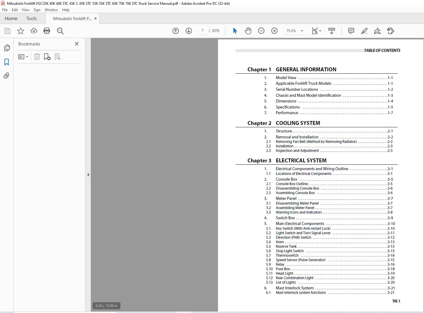
TABLE OF CONTENTS:
Mitsubishi Forklift FGC35K FGC40K FGC40K STC FGC45K C FGC45K STC FGC55K FGC55K STC FGC60K FGC70K FGC70K STC Service Manual – PDF DOWNLOAD
Chapter 1 GENERAL INFORMATION
1 Model View 1-1
2 Applicable Forklift Truck Models 1-1
3 Serial Number Locations 1-2
4 Chassis and Mast Model Identification 1-3
5 Dimensions 1-4
6 Specifications 1-5
7 Performance 1-7
Chapter 2 COOLING SYSTEM
1 Structure 2-1
2 Removal and Installation 2-2
2 1 Removing Fan Belt (Method by Removing Radiator) 2-2
2 2 Installation 2-3
2 3 Inspection and Adjustment 2-3
Chapter 3 ELECTRICAL SYSTEM
1 Electrical Components and Wiring Outline 3-1
1 1 Locations of Electrical Components 3-1
2 Console Box 3-5
2 1 Console Box Outline 3-5
2 2 Disassembling Console Box 3-6
2 3 Assembling Console Box 3-6
3 Meter Panel 3-7
3 1 Disassembling Meter Panel 3-7
3 2 Assembling Meter Panel 3-7
3 3 Warning Icons and Indicators 3-8
4 Switch Box 3-9
5 Main Electrical Components 3-10
5 1 Key Switch (With Anti-restart Lock) 3-10
5 2 Light Switch and Turn Signal Lever 3-11
5 3 Direction (FNR) Switch 3-12
5 4 Horn 3-13
5 5 Reserve Tank 3-13
5 6 Stop Light Switch 3-13
5 7 Thermoswitch 3-14
5 8 Speed Sensor (Pulse Generator) 3-15
5 9 Relay 3-16
5 10 Fuse Box 3-18
5 11 Head Light 3-19
5 12 Rear Combination Light 3-20
5 13 List of Lights 3-20
6 Mast Interlock System 3-21
6 1 Mast interlock system functions 3-21
TABLE OF CONTENTS
TOC-2
7 Driving Interlock System 3-22
7 1 Driving Interlock System Functions 3-22
8 Neutral System 3-23
8 1 Neutral System Functions 3-23
9 Battery and Maintenance 3-24
9 1 State of Charge and Electrolyte Specific Gravity (S G ) Adjustment 3-24
9 2 Specific Gravity Reading and State of Charge 3-24
9 3 Precautions for Battery Charging 3-24
10 Wire Color 3-25
10 1 List of Wire Color Codes 3-25
11 Troubleshooting 3-26
11 1 Starter System 3-26
11 2 Lighting System 3-26
11 3 Alarm Unit 3-27
11 4 Battery 3-27
Chapter 4 POWER TRAIN
1 Specifications 4-1
2 Structure (3 5 to 5 5 Ton) 4-2
3 Structure (6 0 to 7 0 Ton) 4-3
3 1 Reduction Ratio (3 5 to 5 5 Ton) 4-4
3 2 Reduction Ratio (6 0 ton 7 0 Ton) 4-5
4 Removing Engine 4-5
4 1 Preparation 4-5
4 2 Removal Sequence (1) 4-6
4 3 Removal Sequence (2) 4-7
4 4 Removal Sequence (3) 4-8
5 Installing Engine 4-10
5 1 Suggestions for Installation 4-10
6 Removing Transmission and Reduction Differential 4-10
6 1 Preparation 4-10
6 2 Removal Sequence 4-11
6 3 Suggestions for Removal 4-11
7 Installing Transmission and Reduction Differential 4-12
7 1 Suggestions for installation 4-12
8 Service Data 4-12
Chapter 5 POWERSHIFT TRANSMISSION
1 Specifications 5-1
1 1 1-Speed Transmission (3 5 to 5 5 Ton) 5-1
2 Structure 5-2
2 1 Torque Converter 5-2
2 2 Transmission 1-Speed 5-3
2 3 Powershift Control 5-4
2 4 Control Valve 5-4
TABLE OF CONTENTS
TOC-3
2 5 Powershift Transmission Control 5-5
3 Removal and Installation 5-6
3 1 Removal 5-6
3 2 Installation 5-6
4 Disassembling Torque Converter 5-7
4 1 Disassembly Sequence 5-7
4 2 Suggestions for Disassembly 5-7
5 After Disassembling Torque Converter 5-8
5 1 Pump Impeller 5-8
5 2 Stator Assembly 5-8
5 3 Turbine Runner 5-8
5 4 Pilot Boss 5-9
5 5 Flexible Plate 5-9
6 Assembling Torque Converter 5-10
6 1 Assembly Sequence 5-10
6 2 Suggestions for Assembly 5-11
7 Disassembling Transmission 5-12
7 1 Control Valve and Strainer 5-12
7 2 Pump Body Assembly 5-13
7 3 Countershaft (2nd Shaft) 5-14
7 4 Countershaft (3rd Shaft) 5-15
7 5 Countershaft (3rd Shaft) 5-15
7 6 Forward-Reverse Clutch Shaft (Current Production) 5-17
7 7 Forward-Reverse Clutch Shaft (First Production) 5-18
8 Inspection and Repair After Disassembling Transmission 5-19
8 1 Oil Pump 5-19
8 2 Pump Boss 5-20
8 3 Stator Shaft 5-20
8 4 Clutch Pistons 5-20
8 5 Friction Plates and Mating Plates 5-20
8 6 Clutch Drums 5-21
8 7 Clutch Gears (Forward and Reverse) 5-21
8 8 Turbine Shaft and Clutch Shaft 5-22
8 9 Clutch Shaft, Countershaft, and Output Shaft 5-22
8 10 Gears 5-22
8 11 Strainer Assembly 5-22
9 Assembling Forward-Reverse Clutch Shaft Subassembly 5-23
9 1 Assembly Sequence 5-23
10 Assembling Forward-Reverse Clutch Shaft (1st Shaft) 5-24
10 1 Preparation 5-24
10 2 Assembly Sequence 5-24
10 3 Suggestions for Assembly 5-24
11 Assembling Output Shaft (4th Shaft) 5-26
11 1 Assembly Sequence 5-26
11 2 Suggestions for Assembly 5-26
12 Assembling Countershaft (3rd Shaft) 5-27
12 1 Assembly Sequence 5-27
12 2 Suggestions for Assembly 5-27
TABLE OF CONTENTS
TOC-4
13 Assembling Countershaft (3rd Shaft) 5-28
13 1 Assembly Sequence 5-28
13 2 Suggestions for Assembly 5-28
14 Assembling Pump Body Assembly 5-29
14 1 Assembly Sequence 5-29
14 2 Suggestions for Assembly 5-29
15 Assembling Control Valve and Strainer 5-30
16 Disassembling Control Valve 5-30
16 1 Disassembly Sequence 5-30
17 After Disassembling Control Valve 5-31
18 Assembling Control Valve 5-33
18 1 Preparation 5-33
18 2 Assembly Sequence 5-33
19 Adjustment 5-34
19 1 Oil Pressure Measurement 5-34
19 2 Inching Valve Test 5-35
19 3 Stall Speed Measurement 5-35
19 4 10 Meters (33-ft) Starting Acceleration Test 5-36
19 5 Adjusting Brake Pedal 5-36
19 6 Adjusting Inching Pedal 5-38
20 Specifications 5-40
20 1 Automatic 2-speed Transmission (6 0 to 7 0 Ton) 5-40
21 Structure 5-41
21 1 Transmission 2-speed 5-41
21 2 Automatic 2-speed Change Mechanism 5-42
21 3 Control System 5-43
21 4 Solenoid Valve 5-44
21 5 Powershift Transmission Hydraulic System Schematic 1-Speed 5-45
21 6 Powershift Transmission Hydraulic System Schematic 2-Speed 5-46
21 7 Hydraulic Control (Forward 1st Speed) 5-47
21 8 Hydraulic Control (Forward 2nd Speed) 5-48
22 Disassembling Transmission 5-49
22 1 Control Valve and Side Cover 5-49
22 2 Output Shaft (4th Shaft) 5-50
22 3 Pump Body 5-52
22 4 Countershaft (3rd Shaft) 5-53
22 5 Input Shaft (1st Shaft / Current Production) 5-54
22 6 Input Shaft (1st Shaft ) 5-55
22 7 Countershaft (2nd Shaft / Current Production) 5-57
22 8 Countershaft (2nd Shaft / First Production) 5-58
23 After Disassembling Transmission 5-59
23 1 Input Shaft, Servo Case, and Sealrings 5-59
24 Assembling Transmission 5-60
24 1 Ball Bearing and Oil Seals 5-60
24 2 Countershaft (2nd Shaft) and Input Shaft (1st Shaft) 5-61
24 3 Countershaft (3rd Shaft) 5-63
24 4 Pump Body 5-64
TABLE OF CONTENTS
TOC-5
24 5 Output Shaft 5-65
24 6 Torque Converter 5-66
25 Assembling Control Valve and Side Cover 5-67
25 1 Suggestions for Assembly 5-67
26 Disassembling Solenoid Valve 5-68
26 1 Disassembly Sequence 5-68
27 After Disassembling Solenoid Valve 5-68
28 Assembling Solenoid Valve 5-69
28 1 Preparation 5-69
28 2 Assembly Sequence 5-69
29 Adjustment 5-69
29 1 Oil Pressure Measurement 5-69
29 2 Hydraulic Pressure Test Tools 5-70
29 3 2nd Speed/Auto Selector Switch Test 5-71
29 4 2-Speed Transmission Electrical Systems Part Numbers 5-71
29 5 ECU Self-Diagnostic Test 5-72
29 6 ECU Test 5-72
29 7 Pulse Generator Test 5-73
29 8 Solenoid Voltage Test 5-73
29 9 Oscilloscope Shop Test 5-74
30 Troubleshooting 5-76
30 1 Torque Converter Drive Transmission 5-76
31 Service Data 5-81
31 1 Torque Converter Drive Transmission 5-81
31 2 Torque Converter Drive Transmission 5-82
31 3 Torque Converter Drive Transmission 5-84
31 4 Torque Converter Drive Transmission (1-Speed Transmission) 5-85
31 5 Torque Converter Drive Transmission (Automatic 2-Speed Transmission) 5-86
31 6 Torque Converter Drive Transmission (Automatic 2-Speed Transmission) 5-87
31 7 Torque Converter Drive Transmission 5-89
31 8 Torque Converter Drive Transmission 5-90
Chapter 6 FRONT AXLE AND REDUCTION DIFFERENTIAL
1 Specifications 6-1
2 Structure 6-2
3 Removing Front Tire 6-3
3 1 Preparation 6-3
4 Installing Front Tire 6-4
5 Removing Front Axle Assembly 6-5
5 1 Preparation 6-5
5 2 Removal Sequence 6-5
5 3 Suggestions for Removal 6-6
6 Installing Front Axle Assembly 6-6
7 Removing and Installing Reduction and Differential 6-6
8 Disassembling Axle Shaft and Hub 6-7
8 1 Preparation 6-7
TABLE OF CONTENTS
TOC-6
8 2 Disassembly Sequence 6-7
8 3 Suggestions for Disassembly 6-8
9 Inspection and Repair After Disassembling Axle Shaft and Hub 6-9
9 1 Axle Shaft 6-9
9 2 Retainer 6-9
9 3 Front Hub Drum 6-9
10 Assembling Axle Shaft and Hub 6-10
10 1 Assembly Sequence 6-10
10 2 Suggestions for Assembly 6-11
11 Disassembling Reduction Differential 6-12
11 1 Preparation 6-12
11 2 Disassembly Sequence 6-12
11 3 Suggestions for Disassembly 6-13
11 4 Removing Bearing 6-13
12 Inspection and Repair After Disassembling Reduction Differential 6-14
12 1 Reduction Bevel Gear 6-14
12 2 Differential 6-14
13 Assembling Reduction Differential 6-15
13 1 Assembly Sequence 6-15
13 2 Suggestions for Assembly 6-15
14 Adjustment 6-17
14 1 Adjusting Bearing Preload 6-17
14 2 Inspecting Back Runout 6-17
14 3 Adjusting Backlash 6-18
14 4 Adjusting Tooth Contact 6-18
14 5 Tooth Contact of Reduction Gear 6-19
15 Troubleshooting 6-20
16 Service Data 6-21
16 1 Front Axle 6-21
Chapter 7 REAR AXLE
1 Specifications 7-1
2 Structure 7-2
2 1 Rear Axle (3 5 to 5 5 Ton) 7-2
2 2 Rear Axle (6 0 to 7 0 Ton) 7-2
2 3 Steering Cylinder 7-3
3 Removing Rear Tires 7-4
3 1 Preparation 7-4
3 2 Removal Sequence 7-4
3 3 Suggestions for Removal 7-4
4 Installing Rear Tires 7-5
4 1 Suggestions for Installation 7-5
5 Removing Rear Axle 7-7
5 1 Suggestions for Removal 7-7
5 2 Removal Sequence 7-7
6 Installing Rear Axle 7-8
TABLE OF CONTENTS
TOC-7
7 Disassembling Rear Axle Assembly 7-9
7 1 Rear Axle (3 5 to 5 5 Ton) 7-9
7 2 Rear Axle (6 0 to 7 0 Ton) 7-10
8 Assembling Rear Axle Assembly 7-12
8 1 Assembly Sequence 7-12
8 2 Suggestion for Assembly 7-13
9 Disassembling Steering Cylinder 7-15
9 1 Disassembly Sequence 7-15
10 Inspection and Repair After Disassembling Steering Cylinder 7-16
11 Assembling Steering Cylinder 7-17
11 1 Assembly Sequence 7-17
11 2 Suggestions for Assembly 7-17
12 Adjustment 7-18
12 1 Adjusting Minimum Turning Radius 7-18
13 Troubleshooting 7-20
14 Service Data 7-21
Chapter 8 BRAKE SYSTEM
1 Specifications 8-1
2 Structure 8-2
2 1 Brake System 8-2
2 2 Master Cylinder and Reserve Tank 8-3
2 3 Wheel Brake 8-4
2 4 Brake Booster (3 5 to 5 5 Ton) 8-5
2 5 Brake Booster (6 0 to 7 0 Ton) 8-6
3 Disassembling Master Cylinder 8-7
3 1 Disassembly Sequence 8-7
4 Inspection and Repair After Disassembling Master Cylinder 8-8
4 1 Cylinder Body 8-8
4 2 Piston 8-8
4 3 Return Spring 8-8
5 Assembling Master Cylinder 8-9
5 1 Assembly Sequence 8-9
5 2 Suggestions for Assembly 8-9
6 Disassembling Wheel Cylinder 8-10
6 1 Disassembling Sequence 8-10
7 Inspection and Repair After Disassembling Wheel Cylinder 8-11
7 1 Cylinder Body 8-11
7 2 Piston 8-11
7 3 Piston Cups 8-11
7 4 Boot 8-11
8 Assembling Wheel Cylinder 8-11
9 Disassembling Wheel Brake 8-12
9 1 Preparation 8-12
9 2 Disassembly Sequence 8-12
TABLE OF CONTENTS
TOC-8
9 3 Suggestions for Disassembly 8-13
10 Inspection and Repair After Disassembling Wheel Brake 8-14
10 1 Backing Plate 8-14
10 2 Shoe and Lining Assembly 8-14
10 3 Brake Drums 8-14
10 4 Adjusting Screw 8-14
10 5 Parking Brake Link 8-15
10 6 Other Inspection Parts 8-15
11 Assembling Wheel Brake 8-16
11 1 Assembly Sequence 8-16
11 2 Suggestions for Assembly 8-17
12 Inspecting and Repairing Parking Brake Lever 8-18
12 1 Parking Brake Lever Components 8-18
12 2 Suggestions for Inspection and Repair 8-19
12 3 Installing Parking Brake Lever 8-19
13 Adjustment 8-20
13 1 Automatic Adjuster Test 8-20
13 2 Procedure for Manual Adjustment 8-20
13 3 Brake Fluid Line Bleeding 8-21
13 4 Inspecting Reserve Tank Level Sensor 8-21
13 5 Procedures for Brake Pedal Adjustment 8-22
13 6 Brake Booster Test 8-23
14 Troubleshooting 8-25
15 Service Data 8-27
Chapter 9 STEERING SYSTEM
1 Specifications 9-1
2 Structure 9-2
2 1 Steering System 9-2
2 2 Steering Control Valve 9-3
2 3 Tilt Steering Assembly 9-4
3 Removing Tilt Steering and Steering Control Valve Assembly 9-5
3 1 Removal Sequence 9-5
3 2 Suggestions for Removal 9-6
4 Inspection After Installing Tilt Steering and Steering Control Valve
Assembly 9-7
4 1 Steering Wheel Play 9-7
4 2 Steering 9-7
4 3 Air Bleeding 9-7
5 Disassembling Steering Control Valve 9-8
5 1 Disassembly Sequence 9-8
5 2 Suggestions for Disassembly 9-9
6 Inspection and Repair After Disassembling Steering Control Valve 9-10
7 Assembling Steering Control Valve 9-10
7 1 Assembly Sequence 9-10
7 2 Suggestions for Assembly 9-11
TABLE OF CONTENTS
TOC-9
8 Troubleshooting 9-15
9 Service Data 9-16
9 1 Steering Control Valve 9-16
Chapter 10 HYDRAULIC SYSTEM
1 Specifications 10-1
2 Structure 10-2
2 1 Hydraulic Line (6 to 7 Ton) 10-2
2 2 Hydraulic Tank 10-3
2 3 Gear Pump 10-4
2 4 Control Valve 10-5
2 5 Inlet Section 10-6
2 6 Solenoid Section 10-7
2 7 Lift Valve Assembly 10-8
2 8 Tilt Valve Assembly 10-9
2 9 Attachment Valve Assembly 10-10
2 10 Control Valve Hydraulic Circuit Diagram 10-11
2 11 Lift and Tilt Cylinders 10-12
2 12 Flow Regulator Valve 10-20
2 13 Down Safety Valve 10-21
3 Removing Gear Pump 10-22
3 1 Preparation for Removal 10-22
3 2 Removal Sequence 10-22
3 3 Suggestions for Removal 10-23
4 Removing Control Valve 10-24
4 1 Preparation for Removal 10-24
4 2 Removal Sequence 10-24
5 Removing Lift Cylinders (Simplex Mast) 10-25
5 1 Removal Sequence 10-25
5 2 Suggestions for Removal 10-25
6 Installing Lift Cylinders (Simplex Mast) 10-27
6 1 Installation 10-27
7 Removing Lift Cylinders (Duplex and Triplex Mast) 10-28
7 1 Removal Sequence 10-28
7 2 Suggestions for Removal 10-29
8 Installing Lift Cylinders (Duplex and Triplex Mast) 10-31
9 Removing Tilt Cylinders 10-32
9 1 Removal Sequence 10-32
9 2 Preparation 10-32
9 3 Suggestions for Removal 10-32
10 Disassembling Gear Pump 10-33
10 1 Disassembly Sequence 10-33
10 2 Suggestions for Disassembly 10-33
11 Inspection After Disassembling Gear Pump 10-34
11 1 Drive and Driven Gears 10-34
11 2 Pump Covers, Body, and Bushings 10-34
TABLE OF CONTENTS
TOC-10
12 Assembling Gear Pump 10-35
12 1 Assembly Sequence 10-35
12 2 Suggestions for Assembly 10-35
13 Inspection After Disassembling Control Valve 10-36
13 1 Sections, Spools, and Return Springs 10-36
14 Assembling Control Valve 10-37
15 Disassembling Lift Cylinders (Simplex Mast) 10-38
15 1 Disassembly Sequence (A40A) 10-38
15 2 Suggestions for Disassembly 10-38
15 3 Disassembly Sequence (A45A, A55A, and A70A) 10-39
15 4 Suggestions for Disassembly 10-39
16 Inspection After Disassembling Lift Cylinders (Simplex Mast) 10-40
16 1 Cylinder Tube 10-40
16 2 Piston Rod 10-40
16 3 Packings and Rings 10-40
17 Assembling Lift Cylinders (Simplex Mast) 10-40
17 1 Assembly Sequence 10-40
17 2 Suggestions for Assembly 10-41
18 Disassembling Lift Cylinders (Duplex and Triplex Masts) 10-42
18 1 Disassembly Sequence for First Lift Cylinders (B55A and C40A Through C70A)
10-42
18 2 Suggestions for Disassembly 10-42
18 3 Disassembly Sequence for Second Lift Cylinders (B40A) 10-43
18 4 Suggestions for Disassembly 10-43
18 5 Disassembly Sequence for Second Lift Cylinders (B45A and B55A) 10-44
18 6 Suggestions for Disassembly 10-44
19 Inspection After Disassembling Lift Cylinders (Duplex and Triplex Masts
) 10-45
19 1 Cylinder Tube 10-45
19 2 Piston rod 10-45
19 3 Packings and rings 10-45
20 Assembling Lift Cylinders (Duplex and Triplex Masts) 10-45
20 1 First Lift Cylinder (B40A Through B55A, and C40A Through C70A) 10-45
20 2 Second Lift Cylinders (B40A) 10-46
20 3 Second Lift Cylinders (B45A and B55A) 10-46
21 Disassembling Lift Cylinders (Triplex Masts) 10-48
21 1 Second Lift Cylinders (C40A) 10-48
21 2 Second Lift Cylinders (C45A and C55A) 10-49
21 3 Second Lift Cylinders (C70A) 10-50
22 Inspection After Disassembling Lift Cylinders (Triplex Masts) 10-51
22 1 Cylinder Tube 10-51
22 2 Piston Rod 10-51
22 3 Packings and Rings 10-51
23 Assembling Lift Cylinders (Triplex Masts) 10-52
23 1 Second Lift Cylinder (C40A) 10-52
23 2 Second Lift Cylinders (C45A and C55A) 10-52
23 3 Second Lift Cylinders (C70A) 10-53
TABLE OF CONTENTS
TOC-11
24 Disassembling Tilt Cylinders 10-54
24 1 Disassembly Sequence 10-54
24 2 Suggestions for Disassembly 10-55
25 Inspection After Disassembling Tilt Cylinders 10-55
25 1 Cylinder Tube 10-55
25 2 Piston Rod 10-55
25 3 Packings and Rings 10-56
26 Assembling Tilt Cylinders 10-57
26 1 Suggestions for Assembly 10-57
27 Disassembling Flow Regulator Valve 10-58
27 1 Flow Regulator Valve (3 5 to 5 5 Ton) 10-58
28 Inspection After Disassembling Flow Regulator Valve 10-58
29 Assembling Flow Regulator Valve 10-59
29 1 Flow Regulator Valve 10-59
30 Inspection After Disassembling Flow Regulator Valve 10-59
31 Assembling Flow Regulator Valve 10-59
32 Inspection and Adjustment 10-60
32 1 Hydraulic Oil Level 10-60
32 2 Test-run of Gear Pump 10-61
32 3 Control Valve 10-62
32 4 Main Relief Valve Adjustment 10-63
32 5 Attachment Relief Valve Adjustment 10-63
32 6 Priority Relief Valve Function Check 10-64
32 7 Flow Regulator Valve Adjustment 10-64
32 8 Lift and Tilt Cylinders 10-65
32 9 Tests 10-67
33 Hydraulic Circuit Diagram 10-68
34 Troubleshooting 10-69
35 Service Data 10-72
35 1 Lift Cylinder (Simplex Mast) 10-73
35 2 Second Lift Cylinders (Duplex Mast Second Cylinders) 10-74
35 3 First Lift Cylinders (Duplex Mast, Triplex Mast First Cylinder) 10-75
35 4 Second Lift Cylinders (Triplex Mast) 10-76
35 5 Tilt Cylinders 10-77
Chapter 11 MAST AND FORKS
1 Simplex Mast 11-1
1 1 Mast System 11-1
1 2 Structure and Functions 11-2
1 3 Removal Sequence of Mast and Lift Bracket Assembly 11-4
1 4 Suggestions for Removing Mast and Lift Bracket Assembly 11-4
1 5 Suggestions for Installing Mast and Lift Bracket Assembly 11-7
1 6 Removal Sequence of Mast and Lift Bracket 11-8
1 7 Suggestions for Disassembling Mast and Lift Bracket 11-8
1 8 Inspecting Mast and Lift Bracket 11-9
1 9 Assembly Sequence of Lift Bracket Roller 11-10
TABLE OF CONTENTS
TOC-12
1 10 Adjusting Lift Bracket Clearance 11-10
1 11 Installing Outer/Inner Mast Rollers 11-14
1 12 Installing Mast Strips 11-15
1 13 Installing Lift Cylinders 11-16
1 14 Connecting Chains 11-17
1 15 Installing Hydraulic Lines 11-19
1 16 Removing and Installing Mast Rollers and Strips Without Removing Mast From
Forklift Truck 11-21
1 17 Inspection and Adjustment 11-23
1 18 Inspecting Forks 11-23
1 19 Inspecting and Adjusting Chain Tension 11-24
1 20 Checking Chain Elongation 11-25
1 21 Adjusting Clearance Between Lift Bracket Roller and Inner Mast 11-26
1 22 Adjusting Mast Roller Clearance 11-28
1 23 Inspecting and Adjusting Mast Strip Clearance 11-30
1 24 Adjusting Mast Tilt Angle 11-30
1 25 Inspecting and Adjusting Right and Left Lift Cylinder Stroke 11-31
1 26 Troubleshooting 11-32
1 27 Service Data 11-33
2 Duplex Mast 11-35
2 1 Mast System 11-35
2 2 Structure and Functions 11-36
2 3 Removal Sequence of Mast and Lift Bracket Assembly 11-38
2 4 Suggestions for Removing Mast and Lift Bracket Assembly 11-38
2 5 Suggestions for Installing Mast and Lift Bracket Assembly 11-40
2 6 Removal Sequence of Mast and Lift Bracket 11-41
2 7 Preparation for Disassembling Mast and Lift Bracket 11-41
2 8 Suggestions for Disassembling Mast and Lift Bracket 11-42
2 9 Inspecting Mast and Lift Bracket 11-43
2 10 Assembly Sequence of Lift Bracket Roller 11-44
2 11 Adjusting Lift Bracket Clearance 11-45
2 12 Installing Outer/Inner Mast Rollers 11-49
2 13 Installing Mast Strips 11-50
2 14 Installing Second Lift Cylinder 11-51
2 15 Installing First Lift Cylinder 11-52
2 16 Connecting Chains 11-53
2 17 Installing Hydraulic Lines 11-55
2 18 Removing and Installing Mast Rollers and Strips Without Removing Mast From
Forklift Truck 11-57
2 19 Inspection and Adjustment 11-58
2 20 Inspecting Forks 11-58
2 21 Inspecting and Adjusting Chain Tension 11-59
2 22 Checking Chain Elongation 11-60
2 23 Adjusting Clearance Between Lift Bracket Roller and Inner Mast 11-61
2 24 Adjusting Mast Roller Clearance 11-63
2 25 Inspecting and Adjusting Mast Strip Clearance 11-65
2 26 Adjusting Mast Tilt Angle 11-65
2 27 Inspecting and Adjusting Right and Left Second Lift Cylinder Stroke 11-66
2 28 Troubleshooting 11-67
2 29 Service Data 11-68
TABLE OF CONTENTS
TOC-13
3 Triplex Mast 11-70
3 1 Mast System 11-70
3 2 Structure and Functions 11-71
3 3 Removal Sequence of Mast and Lift Bracket Assembly 11-73
3 4 Suggestions for Removing Mast and Lift Bracket Assembly 11-73
3 5 Suggestions for Installing Mast and Lift Bracket Assembly 11-75
3 6 Removal Sequence of Mast and Lift Bracket 11-76
3 7 Preparation for Disassembling Mast and Lift Bracket 11-76
3 8 Suggestions for Disassembling Mast and Lift Bracket 11-77
3 9 Inspecting Mast and Lift Bracket 11-78
3 10 Assembly Sequence of Lift Bracket Roller 11-79
3 11 Adjusting Lift Bracket Clearance 11-80
3 12 Installing Outer/Inner Mast Rollers 11-84
3 13 Installing Mast Strips 11-85
3 14 Installing Second Lift Cylinder 11-86
3 15 Installing First Lift Cylinder 11-87
3 16 Connecting Chains 11-88
3 17 Installing Hydraulic Lines 11-89
3 18 Removing and Installing Mast Rollers and Strips Without Removing Mast From
Forklift Truck 11-91
3 19 Inspection and Adjustment 11-93
3 20 Inspecting Forks 11-93
3 21 Inspecting and Adjusting Chain Tension 11-94
3 22 Checking Chain Elongation 11-95
3 23 Adjusting Clearance Between Lift Bracket Roller and Inner Mast 11-96
3 24 Adjusting Mast Roller Clearance 11-98
3 25 Inspecting and Adjusting Mast Strip Clearance 11-102
3 26 Adjusting Mast Tilt Angle 11-102
3 27 Inspecting and Adjusting Right and Left Second Lift Cylinder Stroke 11-103
3 28 Troubleshooting 11-104
3 29 Service Data 11-105
Chapter 12 SERVICE DATA
1 Maintenance Schedule 12-1
2 Tightening Torques for Standard Bolts and Nuts 12-5
2 1 Metric Fine Thread 12-5
2 2 Metric Coarse Thread 12-7
3 Periodic Replacement Parts 12-9
3 1 Safety Critical Parts 12-9
4 Lubrication Schedule 12-10
4 1 Lubrication Chart 12-10
4 2 Fuel and Lubricant Specifications 12-11
4 3 Adjustment Value and Oil Capacity 12-12
5 Special Tools 12-13
5 1 Special Service Tools 12-13
TABLE OF CONTENTS
TOC-14
Chapter 13 HOW TO READ CIRCUIT DIAGRAMS
1 Description of Circuit Diagrams 13-1
1 1 Circuit Diagrams 13-1
1 2 Connector Diagrams 13-1
2 How to Read Circuit Diagrams 13-2
2 1 Symbols 13-3
2 2 Sheet Symbol 13-6
2 3 Connecting Lines 13-7
2 4 Equipment 13-8
2 5 Relay Contactor and Coil 13-9
2 6 Connectors 13-9
2 7 Indication of Connecting Line 13-10
2 8 Indication of GND (Earth) 13-10
2 9 Indication of Another Specification 13-11
3 How to Read Connector Diagrams 13-12
4 Abbreviation 13-14
Chapter 14 CIRCUIT DIAGRAM
MITSUBISHI FORKLIFT FGC35K FGC40K FGC40K STC FGC45K C FGC45K STC FGC55K FGC55K STC SERVICE MANUAL:
IMAGES PREVIEW OF THE MANUAL:


PLEASE NOTE:
- This is the SAME exact manual used by your dealers to fix your vehicle.
- The same can be yours in the next 2-3 mins as you will be directed to the download page immediately after paying for the manual.
- Any queries / doubts regarding your purchase, please feel free to contact [email protected]