Mitsubishi Forklift OPB12N2F(P) OPB20N2(P) OPB25N2(P) Service Manual – PDF DOWNLOAD
Original price was: $89.95.$32.95Current price is: $32.95.
Mitsubishi Forklift OPB12N2F(P) OPB20N2(P) OPB25N2(P) Service Manual – PDF DOWNLOAD
Pub.No : 639784-EN A
Description
Mitsubishi Forklift OPB12N2F(P) OPB20N2(P) OPB25N2(P) Service Manual – PDF DOWNLOAD
FILE DETAILS:
Mitsubishi Forklift OPB12N2F(P) OPB20N2(P) OPB25N2(P) Service Manual – PDF DOWNLOAD
Format: PDF
Language: English
Brand: Mitsubishi
MITSUBISHI FORKLIFT OPB12N2F(P) OPB20N2(P) OPB25N2(P) SERVICE MANUAL – PDF DOWNLOAD:
IMAGES PREVIEW OF THE MANUAL:
DESCRIPTION:
Mitsubishi Forklift OPB12N2F(P) OPB20N2(P) OPB25N2(P) Service Manual – PDF DOWNLOAD
FOREWORD:
This service manual is a guide for servicing lift trucks. The long productive life of your lift truck depends on regular and proper servicing, consistent with the instructions provided in this service manual. Before you start to test, repair or rebuild a lift truck, read the respective sections of this manual carefully and make sure that you know all of the components. The descriptions, illustrations and specifications contained in this manual are for lift trucks with serial numbers in effect at the time of printing. The manufacturer reserves the right to change specifications or designs without notice and without incurring obligations. For your convenience, the instructions are grouped by systems as an easy reference. Unauthorized copying and lending of this material is strictly prohibited.
Service area safety:
• Keep the servicing area clean. Oil, grease, and water make the floor slippery.
• If possible, make all repairs with the truck parked on a level, hard surface.
• Before you start to do repairs on the truck, hang a Do not Operate sign in the operator compartment.
• The truck must always be supported on jacks, if someone works under it.
• Do not work on any truck that is supported only by lift jacks or a hoist. Always use jack stands or other supports to support the truck before doing any disassembly.
• Lower the forks or other implements to the ground before performing any work on the truck. If this cannot be done, make sure the forks or other implements are blocked correctly to make sure that they do not fall unexpectedly.
• Use steps and grab handles (if applicable) when you mount or dismount a truck. Clean mud or debris from the steps, walkways or work platforms before use. Always face the truck when you use steps, ladders and walkways. When it is not possible to use the designed access system, use ladders, scaffolds, or work platforms to perform safe repair operations.
• To avoid back injury, use a hoist when you lift components that weigh 23 kg (51 lb) or more. Make sure that all chains, hooks, slings, etc., are in good condition and of the correct capacity. Make sure that all hooks are positioned correctly. Lifting eyes are not to be side-loaded during a lifting operation.
• Make sure that all protective devices including guards and shields are properly installed and functioning correctly before you start a repair. If a guard or shield must be removed to perform the repair work, be even more careful than usually.
• Always support the mast and carriage to keep the carriage or attachments raised when you perform maintenance or repair work that requires the mast to be in the lifted position.
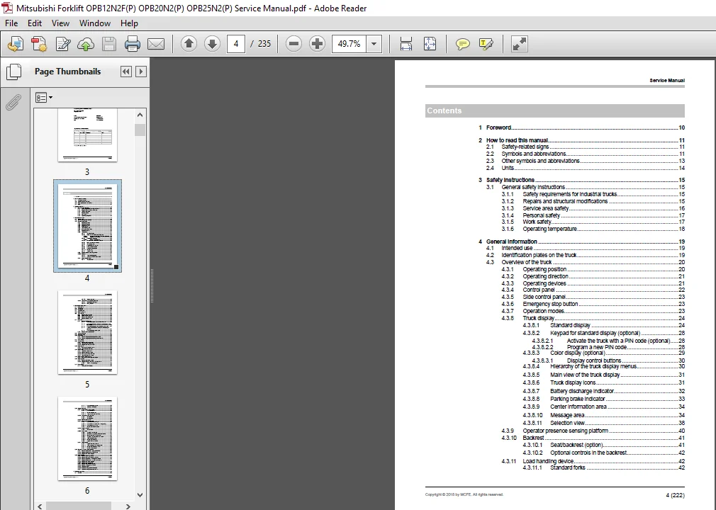
TABLE OF CONTENTS:
Mitsubishi Forklift OPB12N2F(P) OPB20N2(P) OPB25N2(P) Service Manual – PDF DOWNLOAD
1 Foreword 10
2 How to read this manual 11
2 1 Safety-related signs 11
2 2 Symbols and abbreviations 11
2 3 Other symbols and abbreviations 13
2 4 Units 14
3 Safety instructions 15
3 1 General safety instructions 15
3 1 1 Safety requirements for industrial trucks 15
3 1 2 Repairs and structural modifications 15
3 1 3 Service area safety 16
3 1 4 Personal safety 17
3 1 5 Work safety 17
3 1 6 Operating temperature 18
4 General information 19
4 1 Intended use 19
4 2 Identification plates on the truck 19
4 3 Overview of the truck 20
4 3 1 Operating position 20
4 3 2 Operating direction 21
4 3 3 Operating devices 21
4 3 4 Control panel 22
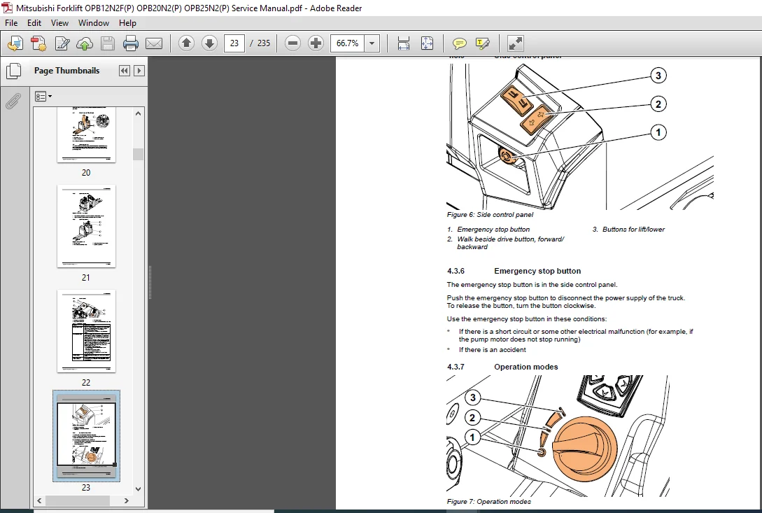
4 3 5 Side control panel 23
4 3 6 Emergency stop button 23
4 3 7 Operation modes 23
4 3 8 Truck display 24
4 3 8 1 Standard display 24
4 3 8 2 Keypad for standard display (optional) 28
4 3 8 2 1 Activate the truck with a PIN code (optional) 28
4 3 8 2 2 Program a new PIN code 28
4 3 8 3 Color display (optional) 29
4 3 8 3 1 Display control buttons 30
4 3 8 4 Hierarchy of the truck display menus 30
4 3 8 5 Main view of the truck display 31
4 3 8 6 Truck display icons 31
4 3 8 7 Battery discharge indicator 32
4 3 8 8 Parking brake indicator 33
4 3 8 9 Center information area 34
4 3 8 10 Message area 34
4 3 8 11 Selection view 38
4 3 9 Operator presence sensing platform 40
4 3 10 Backrest 41
4 3 10 1 Seat/backrest (option) 41
4 3 10 2 Optional controls in the backrest 42
4 3 11 Load handling device 42
4 3 11 1 Standard forks 42
Copyright © 2018 by MCFE All rights reserved 4 (222)
Service Manual
4 3 11 2 Simplex mast unit 43
4 3 12 Second level order picking (optional) 43
4 3 12 1 Climbing rails and steps 44
4 3 12 2 Lifting platform 44
5 Mechanical maintenance 46
5 1 Lifting points 46
5 2 Jack points 46
5 3 Hoist points 46
5 4 Transportation 47
5 5 Order spare parts 47
5 6 Truck covers 48
5 6 1 Remove the front cover 48
5 6 2 Open the battery cover 49
5 6 3 Remove the load backrest 50
5 6 4 Remove the back cover 50
5 7 Drive unit 50
5 7 1 Remove the drive unit 51
5 7 1 1 Remove the steering motor of the drive unit 52
5 7 1 2 Remove the traction motor and transmission gear from
the drive unit 53
5 7 1 3 Remove the traction motor from transmission gear 54
5 7 1 4 Assemble the traction motor and transmission gear
connection 54
5 7 1 5 Remove the transmission gear 55
5 7 2 Remove the magnetic brake 57
5 8 Transmission gear 57
5 9 Slewing bearing 58
5 10 Pump motor 59
5 10 1 Remove the pump motor (standard models) 59
5 10 2 Remove the pump motor (Lifting platform models) 60
5 11 Truck wheels 62
5 12 Traction wheel 63
5 12 1 Remove the traction wheel 63
5 12 2 Assemble the traction wheel 65
5 12 3 Replace the wheel shaft bolts 66
5 13 Load wheels 68
5 13 1 Disassemble the load wheel 68
5 13 2 Assemble the load wheel 68
5 14 Castor wheel 69
5 14 1 Adjust the castor wheel 69
5 14 2 Remove the castor wheel 70
5 14 3 Disassemble the castor wheel 70
5 14 4 Assemble the castor wheel 71
5 15 Lifting system and fork carriage 71
5 15 1 Disassemble the linkage mechanism 72
5 16 Steering wheel 75
5 16 1 Remove the steering wheel 75
5 16 2 Replace the gas spring of the steering wheel 77
5 16 2 1 Install a new gas spring 79
5 17 Color display 80
5 17 1 Change the color display 80
Copyright © 2018 by MCFE All rights reserved 5 (222)
Service Manual
5 17 1 1 Remove the color display 80
5 17 1 2 Install the color display 81
5 18 Simplex mast unit 83
5 18 1 Maintenance of the mast unit 83
5 18 1 1 Daily maintenance 83
5 18 1 2 Monthly maintenance 84
5 18 1 3 Annual maintenance (1000 h) 84
5 18 2 Lubricant recommendations 84
5 18 2 1 Mast chains 84
5 18 2 2 Mast channels 84
5 18 3 Remove the mast unit 84
5 18 4 Disassemble the mast unit 86
5 18 4 1 Remove the lifting carriage 87
5 18 4 2 Remove the main rollers of the lifting carriage 88
5 18 4 3 Remove the mast cylinder 88
5 18 4 4 Disassemble the chain yoke 89
5 18 5 Inspect the forks 90
5 18 5 1 Welded forks 90
5 18 6 Mast chains 91
5 18 6 1 Inspect the mast chains 91
5 18 6 2 Measure the elongation of the mast chains 92
5 18 6 3 Maintenance of the mast chains 94
5 18 6 4 Inspect the tension of the mast chains 98
5 18 6 5 Adjust the mast chains 98
5 18 6 6 Disassemble the chains 98
5 18 6 7 Replace the mast chains 99
5 18 7 Lifting cylinder 102
5 18 7 1 Replace the lifting cylinder 102
5 18 7 2 Sealing housing of the lifting cylinder 105
5 18 7 3 Disassemble the lifting cylinder 105
5 18 7 4 Bleed the mast cylinder 106
5 19 Operator presence sensing platform 108
5 19 1 Remove the operator sensing platform floor 109
5 19 2 Replace the operator platform sensor 109
5 19 3 Replace the rubber stoppers 111
5 20 Lifting platform 112
5 20 1 Remove the lifting platform 112
5 20 2 Remove the floor of the lifting platform 115
5 20 3 Remove the battery of a lifting platform truck 116
5 20 4 Replace the operator presence pedal sensor 117
5 20 5 Replace the rubber stoppers 118
5 20 6 Replace the wiring harness 118
5 20 7 Remove the foot lowering pedal 121
5 20 8 Bleed the lifting platform cylinder 122
5 20 9 Guidance rollers 123
5 20 10 Adjust the lifting platform sideways 124
5 20 11 Adjust the lifting platform machine-way 125
6 Electrical operation 126
6 1 Overview 126
Copyright © 2018 by MCFE All rights reserved 6 (222)
Service Manual
6 2 Power source 126
6 3 Safety circuit (emergency stop button) 126
6 4 Key switch 126
6 5 Traction 127
6 6 AC motor operation 127
7 Batteries 128
7 1 General information 128
7 1 1 Safety with lead-acid batteries 129
7 2 Battery maintenance 129
7 2 1 Daily maintenance 129
7 2 2 Weekly maintenance 130
7 2 3 Annual maintenance 130
7 2 4 General maintenance 130
7 2 5 Storage 130
7 2 6 Malfunctions 131
7 2 7 How to clean batteries 131
7 2 7 1 How to clean vehicle traction batteries 131
7 2 7 2 How to avoid damage to the plastic parts of batteries 132
7 3 Requirements for the battery charging areas 132
7 4 Charge the battery 133
7 4 1 When the battery is charged 135
7 5 Measure the specific gravity of the battery 136
7 6 Acquire a new battery 136
7 7 Replace the battery 136
7 7 1 How to replace the battery 137
8 Electric system maintenance 139
8 1 Control panel 139
8 1 1 Emergency stop button for standard models 139
8 1 2 Key switch 139
8 1 3 Walk beside drive buttons (optional) 140
8 2 Electric panel 140
8 2 1 Discharge the controllers 141
8 2 2 Traction controller 142
8 2 3 Traction controller connector 143
8 2 3 1 CNA external connector 144
8 2 3 2 Description of the power connections 147
8 2 4 Steering controller 147
8 2 4 1 CNA external connector 148
8 2 4 2 Description of the power connectors 149
8 2 5 Contactors and relays 149
8 2 5 1 Contactor functionality check 149
8 2 5 2 Remove the controllers 150
8 2 5 3 Remove the contactors 151
8 2 6 Fuses 153
8 2 7 Replace the truck connector 153
8 3 Motor compartment 155
8 3 1 Magnetic brake 156
8 3 1 1 The air gap of the magnetic brake 156
8 3 1 2 Coil resistance measurement 156
8 3 2 Traction motor 156
Copyright © 2018 by MCFE All rights reserved 7 (222)
Service Manual
8 3 2 1 Temperature sensor check 156
8 3 3 Pump motor 157
8 3 3 1 Solenoid valve 158
8 3 4 Steering motor 160
8 4 Sensors 161
8 4 1 Pressure sensor 162
8 4 2 Steering reference sensor 163
8 4 3 Steering speed sensors 164
8 4 4 Forks lift upper limit sensor 164
8 4 4 1 Adjust the forks lift upper limit sensor 165
8 4 5 Speed sensor 166
8 4 5 1 Replace the HALL sensor 166
8 4 6 Operator platform sensor 167
8 4 7 Mast operating speed reduction sensor 167
8 4 8 Lifting platform sensors 168
8 4 8 1 Lifting platform lift stop sensor 168
8 4 8 2 Lifting platform lower speed reduction sensor 169
8 4 8 3 Lifting platform lift speed reduction sensor 170
8 4 8 4 Operator presence sensor of the lifting platform 170
8 5 Lifting platform foot lowering pedal 171
8 5 1 Lifting platform pedal functionality check 171
8 6 Horn 172
8 6 1 Diode test with a multimeter 172
9 Electric system adjustments and measurements 173
9 1 Overview 173
9 2 Adjust the electrical steering 173
9 2 1 Assembly of the reference sensors 173
9 2 2 Steering teaching 173
9 3 Insulation resistance test 174
9 3 1 Test voltage 174
9 3 2 Insulation tester check 174
9 3 3 Measure the insulation resistance 174
9 3 3 1 Insulation resistance of the truck 175
9 3 3 2 Insulation resistance of the battery 175
10 Hydraulic operation 177
10 1 Overview 177
10 2 Hydraulic symbols 181
10 3 Hydraulic oil recommendations 182
10 4 Maintenance points of the hydraulic system 183
10 5 Hydraulic aggregate (standard models) 183
10 6 Hydraulic aggregate (lifting platform models) 184
10 7 Hydraulic aggregate (1 2t mast model) 185
10 7 1 Disassemble the hydraulic aggregate 185
10 7 2 Disassemble the hydraulic oil tank 186
10 8 Replace the hydraulic cylinder 187
10 9 Hydraulic system with the lifting platform 189
10 10 Hydraulic system with the simplex mast 191
11 TruckTool Diagnostics 192
11 1 Overview 192
Copyright © 2018 by MCFE All rights reserved 8 (222)
Service Manual
11 2 Location of the service socket 193
11 2 1 Connect TruckTool to the service socket 193
12 Parameter descriptions 194
13 Alarm codes 195
14 Service data 196
14 1 Special tightening torques 196
14 2 Tightening torques for standard bolts 196
14 3 Troubleshooting 197
14 3 1 Standard display messages 198
14 3 2 Troubleshooting case examples 198
14 3 3 Traction 198
14 3 4 Brakes 199
14 3 5 Hydraulics 199
14 3 6 Steering 199
14 3 7 Charging 200
14 4 Lubrication 200
14 4 1 Hydraulic oil 200
14 4 2 Transmission oil 200
14 5 Special tools 200
15 Options 202
16 Technical specifications 205
16 1 Dimensions 205
16 2 Technical data 207
APPENDIX A: Stickers 210
APPENDIX B: Truck display languages 214
APPENDIX C: Maintenance check list 215
Index 218
PLEASE NOTE:
- This is the same manual used by the dealers to diagnose and troubleshoot your vehicle
- You will be directed to the download page as soon as the purchase is completed. The whole payment and downloading process will take anywhere between 2-5 minutes
- Need any other service / repair / parts manual, please feel free to contact [email protected] . We still have 50,000 manuals unlisted