Mitsubishi Forklift RB14N2S RB14N2HS RB16N2 RB16N2H RB16N2S RB16N2HS RB16N2C RB16N2HC Service Manual – PDF DOWNLOAD
Original price was: $98.95.$32.95Current price is: $32.95.
Mitsubishi Forklift RB14N2S RB14N2HS RB16N2 RB16N2H RB16N2S RB16N2HS RB16N2C RB16N2HC RB20N2H RB20N2X RB25N2X Service Manual – PDF DOWNLOAD
RB14N2S, RB14N2HS
RB16N2, RB16N2H, RB16N2S
RB16N2HS, RB16N2C, RB16N2HC
RB20N2H, RB20N2X
RB25N2X
Description
Mitsubishi Forklift RB14N2S RB14N2HS RB16N2 RB16N2H RB16N2S RB16N2HS RB16N2C RB16N2HC RB20N2H RB20N2X RB25N2X Service Manual – PDF DOWNLOAD
FILE DETAILS:
Mitsubishi Forklift RB14N2S RB14N2HS RB16N2 RB16N2H RB16N2S RB16N2HS RB16N2C RB16N2HC RB20N2H RB20N2X RB25N2X Service Manual – PDF DOWNLOAD
Format: PDF
Language: English
Brand: Mitsubishi
MITSUBISHI FORKLIFT RB14N2S RB14N2HS RB16N2 RB16N2H RB16N2S RB16N2HS RB16N2C RB16N2HC SERVICE MANUAL – PDF DOWNLOAD:
IMAGES PREVIEW OF THE MANUAL:
DESCRIPTION:
Mitsubishi Forklift RB14N2S RB14N2HS RB16N2 RB16N2H RB16N2S RB16N2HS RB16N2C RB16N2HC RB20N2H RB20N2X RB25N2X Service Manual – PDF DOWNLOAD
RB14N2S, RB14N2HS
RB16N2, RB16N2H, RB16N2S
RB16N2HS, RB16N2C, RB16N2HC
RB20N2H, RB20N2X
RB25N2X
Foreword :
- This service manual is a guide for servicing lift trucks. The long productive life of your lift truck depends on regular and proper servicing, consistent with the instructions provided in this service manual. Before starting to test, repair or rebuild a lift truck, read the respective sections of this manual carefully and familiarize yourself with all of the components.
- The descriptions, illustrations and specifications contained in this manual are for lift trucks with serial numbers in effect at the time of printing. Trucks are constantly being developed. The graphic illustrations in this manual may differ slightly from the actual design of the truck. The manufacturer reserves the right to modify the design, equipment and technical features without prior notice and without any obligations. For your convenience, the instructions are grouped by systems as an easy reference. Unauthorized copying and lending of this material is strictly prohibited.
Work safety:
- Unauthorized truck modification is not permitted. No modifications or alterations to a powered industrial truck, which could affect, for example, capacity, stability or safety requirements of the truck, shall be made without the prior written approval of the original truck manufacturer, its authorized representative, or a successor thereof.
- This includes changes affecting, for example, braking, steering, visibility and the addition of removable attachments. When the manufacturer or his successor approves a modification or alteration, the manufacturer or successor shall also make and approve appropriate changes to the capacity plate, decals, tags and operation and maintenance handbooks.
- Only in the event that the truck manufacturer is no longer in business and there is no successor in the interest to the business, may the user arrange for a modification or alteration to a powered industrial truck, provided, however, that the user:
a. arranges for the modification or alteration to be designed, tested and implemented by an engineer(s) expert in industrial trucks and their safety,
b. maintains a permanent record of the design, test(s) and implementation of the modification or alteration,
c. approves and makes appropriate changes to the capacity plate(s), decals, tags and instruction handbook, and © Mitsubishi Forklift Trucks 2013. All rights reserved. Revision: A Document ID: 618022 13 (210) PBP Service Manual
d. affixes a permanent and readily visible label to the truck stating the manner in which the truck has been modified or altered, together with the date of the modification or alteration and the name and address of the organization that accomplished those tasks.
• Switch off the truck’s power before opening the cover of the motor compartment or the electrical system.
• Relieve all pressure in the air, oil or water systems before disconnecting or removing any lines, fittings or related items. Release the residual pressure when removing a pressurized device.
• With sit-on trucks, dismount the seat for the duration of the service work.
• Before operating, lubricating or repairing the product, read all warning plates and decals on the truck.
• Do not use your hands to check for oil leaks.
• To avoid burns, pay attention to the hot sections and hot fluids in lines, tubes and compartments, even when the truck is idle or off.
• Only use clean oil in the hydraulic system.
• Repairs requiring welding should be performed only with the appropriate reference information and by personnel adequately trained and knowledgeable in welding procedures. Determine the type of metal and select the correct welding procedure and electrodes, rods or wire to provide a weld metal strength equivalent at least to that of the parent metal.
• When welding, always disconnect the battery and electronic devices. Remove all paint from a 10 cm radius from the welding point to avoid creating toxic gases during welding.
• Use proper lifting procedures when removing any components.
• Be careful when removing cover plates. Gradually remove the last two bolts or nuts located at opposite ends of the cover or device. Before removing the last two bolts or nuts completely, pry the cover loose to relieve any springs or other pressures.
• Be careful when removing filler caps, breathers and plugs on the truck. Wrap a cloth around the cap or plug to prevent being sprayed or splashed by liquids under pressure. Be aware that the danger of being sprayed or splashed is always greater immediately after stopping the truck, as the fluids are very hot.
• Use only well-maintained tools. Also make sure that you use the tools in a proper way.
• Reinstall all fasteners with the same part number. If a replacement is needed, do not use a fastener of lesser quality.
TABLE OF CONTENTS:
Mitsubishi Forklift RB14N2S RB14N2HS RB16N2 RB16N2H RB16N2S RB16N2HS RB16N2C RB16N2HC RB20N2H RB20N2X RB25N2X Service Manual – PDF DOWNLOAD
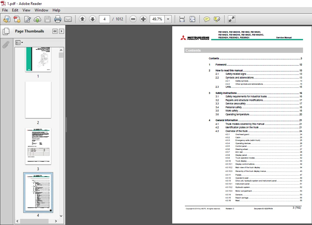
Contents 3
1 Foreword 12
2 How to read this manual 13
2 1 Safety-related signs 13
2 2 Symbols and abbreviations 13
2 2 1 Safety symbols 13
2 2 2 Other symbols and abbreviations 15
2 3 Units 15
3 Safety instructions 16
3 1 Safety requirements for industrial trucks 16
3 2 Repairs and structural modifications 17
3 3 Service area safety 17
3 4 Personal safety 18
3 5 Work safety 18
3 6 Operating temperature 20
4 General information 21
4 1 Truck models covered by this manual 21
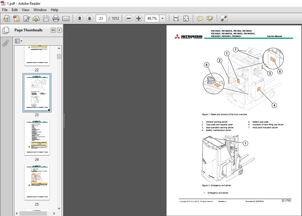
4 2 Identification plates on the truck 21
4 3 Overview of the truck 24
4 3 1 Overhead guard 24
4 3 2 Cabin 25
4 3 3 Emergency exits (cabin truck) 25
4 3 4 Operating devices 26
4 3 5 Control panel 27
4 3 6 Steering wheel 27
4 3 7 Arm rest 28
4 3 8 Display panel 30
4 3 9 Truck operation modes 32
4 3 10 Truck display 33
4 3 10 1 Display control buttons 34
4 3 10 2 Main view of the truck display 34
4 3 10 3 Hierarchy of the truck display menus 43
4 3 11 Pedals 47
4 3 12 Operator’s seat 49
4 3 13 Drive unit, hydraulic system and instrument panel 50
4 3 13 1 Instrument panel 51
4 3 13 2 Hydraulic system 52
4 3 13 3 Motor compartment 53
4 3 14 Sensors 53
4 3 15 Reach carriage 55
4 3 16 Mast 55
Copyright © 2018 by MCFE All rights reserved Revision: C Document ID: 622075-EN 4 (782)
RB14N2S, RB14N2HS, RB16N2, RB16N2H,
RB16N2S, RB16N2HS, RB16N2C, RB16N2HC,
RB20N2H, RB20N2X, RB25N2X Service Manual
4 3 17 Load backrest 56
5 Mechanical maintenance 57
5 1 Lifting points 57
5 1 1 Jack points 57
5 1 2 Hoist points 58
5 2 How to tow the truck 59
5 2 1 Release the magnetic brake manually 60
5 3 Transportation 61
5 4 Assembly and commissioning 63
5 4 1 Install the mast 63
5 5 Order spare parts 66
5 6 How to clean the truck 66
5 7 Truck covers 67
5 7 1 Remove the machinery cover 68
5 7 2 Remove the front bumper 68
5 7 3 Remove the floor plate 68
5 7 4 Open the machinery top cover 69
5 7 5 Open the instrument panel 70
5 7 6 Remove the gas spring of the instrument panel 71
5 7 7 Remove the instrument panel cover 72
5 7 8 Remove the control panel 73
5 7 9 Remove the cup holder 73
5 7 10 Remove the reach carriage cover 73
5 8 Steering wheel 74
5 8 1 Remove the steering wheel 74
5 9 Transmission gear 75
5 9 1 Remove the transmission gear 76
5 10 Slewing bearing 77
5 10 1 Lubricate the slewing bearing 77
5 11 Traction wheel 78
5 11 1 Disassemble the traction wheel 79
5 11 1 1 Replace the wheel shaft bolts 79
5 11 2 Assemble the traction wheel 81
5 12 Corner supports 81
5 12 1 Replace the corner supports 82
5 13 Load wheels 82
5 13 1 Remove the load wheels 83
5 13 2 Electric load wheel brakes (High performance model, optional for
Standard model) 84
5 13 3 Adjust the load wheel brakes (High performance model, optional for
Standard model) 85
5 14 Battery roller frame 89
5 14 1 Remove the battery roller frame 89
5 15 Reach carriage 90
5 15 1 Lubricate the rollers of the reach carriage 90
5 15 2 Adjust the guidance rollers of the reach carriage 91
5 15 3 Sensors of the reach carriage 93
5 15 4 Remove the reach carriage 94
5 15 5 Remove the reach cylinder 95
Copyright © 2018 by MCFE All rights reserved Revision: C Document ID: 622075-EN 5 (782)
RB14N2S, RB14N2HS, RB16N2, RB16N2H,
RB16N2S, RB16N2HS, RB16N2C, RB16N2HC,
RB20N2H, RB20N2X, RB25N2X Service Manual
5 15 6 Replace the reach carriage hoses 97
5 16 Mast 102
5 16 1 Detailed construction 103
5 16 2 Maintenance of the mast 104
5 16 2 1 Daily maintenance 104
5 16 2 2 Monthly maintenance 104
5 16 2 3 Annual maintenance (1,000 h) 104
5 16 3 Lubricant recommendations 105
5 16 3 1 Mast chains 105
5 16 3 2 Mast channels 105
5 16 4 Remove the lifting carriage 105
5 16 5 Remove the mast 108
5 16 6 Disassemble the mast 112
5 16 7 Fork inspection 118
5 16 8 Mast chains 122
5 16 8 1 Inspect the mast chains 123
5 16 8 2 Examine the tension of the mast chains 129
5 16 8 3 Adjust the mast chains 130
5 16 8 4 Replace the mast chains 130
5 16 9 Guidance rollers 133
5 16 9 1 Adjust the guidance rollers 134
5 16 9 2 Replace the guidance rollers 134
5 16 10 Main rollers 136
5 16 10 1 Replace the main rollers 136
5 16 11 Free lift cylinder 138
5 16 11 1 Replace the free lift cylinder 138
5 16 11 2 Sealing housing of the free lift cylinder 141
5 16 11 3 Bleed out the air from the free lift cylinder 142
5 16 12 Side cylinders 144
5 16 12 1 Replace the side cylinders 144
5 16 12 2 Sealing housing of the side cylinder 147
5 16 12 3 Bleed out the air from the side cylinders 149
5 16 13 Tilt cylinders 151
5 16 13 1 Remove the tilt cylinders 151
5 16 13 2 Sealing housing of the tilt cylinder 153
5 16 14 Sideshift cylinder 154
5 16 14 1 Remove the piston of the sideshift cylinder 155
5 16 14 2 Sealing housing of the sideshift cylinder 156
5 17 Load backrest 157
5 17 1 Remove the load backrest 157
5 18 Operator’s seat 158
5 18 1 Replace the seat switch 158
5 19 Arm rest 160
5 19 1 Remove the arm rest 160
5 19 2 Open the arm rest 162
5 19 3 Remove the arm rest levers 162
5 19 4 Remove the arm rest buttons 163
Copyright © 2018 by MCFE All rights reserved Revision: C Document ID: 622075-EN 6 (782)
RB14N2S, RB14N2HS, RB16N2, RB16N2H,
RB16N2S, RB16N2HS, RB16N2C, RB16N2HC,
RB20N2H, RB20N2X, RB25N2X Service Manual
5 20 Cabin 164
5 20 1 Cabin covers 164
5 20 1 1 Remove the instrument panel cover 165
5 20 1 2 Remove the ceiling cover 167
5 20 1 3 Remove the left side cover 168
5 20 1 4 Remove the right side cover 168
5 20 1 5 Remove the operator door cover 169
5 20 2 Operator door 170
5 20 2 1 Replace the gas spring of the operator door 171
5 20 2 2 Remove the operator door 172
5 20 2 3 Replace the lock of the operator door 173
5 20 2 4 Adjust the operator door 175
5 20 3 Roof window 176
5 20 3 1 Open the roof window 176
5 20 3 2 Remove the roof window 177
5 20 3 3 Replace the sunroof wipers 177
5 20 3 4 Remove the motor of the roof window wipers 178
5 20 3 5 Remove the roof window lock 179
5 20 4 Cabin seals 180
5 20 5 Heater 181
5 20 5 1 Remove the heater 181
5 20 5 2 Adjust the heater 183
5 20 6 Loudspeakers 184
5 20 6 1 Replace the loudspeakers 184
5 20 7 Cabin windows 185
6 Electrical operation 186
6 1 How to use the schematic diagram 186
6 2 Power supply 189
6 3 Safety circuit (emergency stop button) 189
6 4 Key switch 189
6 5 Traction 190
7 Battery maintenance 191
7 1 Safety regulations concerning the handling of lead-acid batteries 192
7 2 Battery maintenance 193
7 2 1 Daily maintenance 193
7 2 2 Weekly maintenance 193
7 2 3 Monthly maintenance 193
7 2 4 Annual maintenance 194
7 2 5 General maintenance 194
7 2 6 Storage 194
7 2 7 Malfunctions 194
7 2 8 How to clean batteries 194
7 3 Requirements for battery charging areas 196
7 4 Charge the battery 198
Copyright © 2018 by MCFE All rights reserved Revision: C Document ID: 622075-EN 7 (782)
RB14N2S, RB14N2HS, RB16N2, RB16N2H,
RB16N2S, RB16N2HS, RB16N2C, RB16N2HC,
RB20N2H, RB20N2X, RB25N2X Service Manual
7 5 Measure the specific gravity of the battery 201
7 6 Acquire a new battery 201
7 7 Replace the battery 201
7 7 1 Guide the battery connector cables 206
7 7 2 Quick battery replacement 206
8 Electric system maintenance 207
8 1 Display panel 207
8 1 1 Emergency stop button 208
8 1 1 1 Emergency stop button functionality check 208
8 1 2 Key switch 209
8 1 2 1 Key switch functionality check 209
8 2 Pedals 210
8 2 1 Operator presence pedal 210
8 2 1 1 Operator presence pedal functionality check 211
8 2 1 2 Remove the operator presence pedal 211
8 2 2 Accelerator pedal 212
8 2 2 1 Accelerator pedal functionality check 213
8 2 2 2 Remove the accelerator pedal 213
8 2 3 Brake pedal 214
8 2 3 1 Brake pedal functionality check 215
8 2 3 2 Remove the brake pedal 215
8 3 Instrument panel 216
8 3 1 Discharge the controllers 217
8 3 2 Vehicle controller 218
8 3 3 Vehicle controller connectors 218
8 3 3 1 CNA external connector 219
8 3 3 2 CNB external connector 221
8 3 4 Traction controller 222
8 3 5 Traction controller connectors 223
8 3 5 1 CNA external connector 224
8 3 5 2 Description of the power connections 225
8 3 6 Pump controller 225
8 3 7 Pump controller connectors 226
8 3 7 1 CNA external connector 227
8 3 7 2 Description of the power connections 228
8 3 8 Steering controller 228
8 3 9 Steering controller connectors 229
8 3 9 1 CNA external connector 230
8 3 9 2 Description of the power connections 231
8 3 10 Fuses 231
8 3 11 Additional fuses with the cabin 233
8 4 Motor compartment 234
8 4 1 Traction motor 234
8 4 1 1 Remove the traction motor 235
8 4 1 2 Lubricate the traction motor axle splines 236
8 4 1 3 Temperature sensor check 237
Copyright © 2018 by MCFE All rights reserved Revision: C Document ID: 622075-EN 8 (782)
RB14N2S, RB14N2HS, RB16N2, RB16N2H,
RB16N2S, RB16N2HS, RB16N2C, RB16N2HC,
RB20N2H, RB20N2X, RB25N2X Service Manual
8 4 1 4 HALL sensor 238
8 4 2 Steering motor 239
8 4 2 1 Remove the steering motor 240
8 4 2 2 Temperature sensor check 240
8 4 2 3 HALL sensor 241
8 4 3 Magnetic brake 243
8 4 3 1 Coil resistance measurement 244
8 4 3 2 Install the magnetic brake 244
8 4 3 3 Adjust the air gap of the magnetic brake 245
8 4 4 Release the magnetic brake manually 246
8 5 Pump motor 247
8 5 1 Pump motor (Standard model) 247
8 5 2 Pump motor (High performance model) 248
8 5 3 Replace the pump motor 249
8 5 4 Lubricate the pump axle splines 249
8 5 5 Replace the HALL sensor 251
8 6 Sensors 252
8 6 1 Steering wheel sensor 252
8 6 1 1 Steering wheel sensor functionality check 252
8 6 1 2 Steering control safety circuit check 253
8 6 2 Steering reference sensor 254
8 6 2 1 Steering reference sensor functionality check 255
8 6 3 Reach end stop, retract limit, retract end stop and reach limit switch 255
8 6 3 1 Reach end stop, retract limit, retract end stop and reach limit switch
functionality check 256
8 6 4 Battery lock sensor 256
8 6 4 1 Battery lock sensor functionality check 257
8 6 5 Pressure sensor 257
8 6 5 1 Pressure sensor functionality check 258
8 6 6 Height reference sensor 258
8 6 6 1 Height reference sensor functionality check 259
9 Electric system adjustments and measurements 260
9 1 Calibrate the arm rest levers 260
9 2 Insulation resistance test 260
9 2 1 Test voltage 260
9 2 2 Insulation tester check 260
9 2 3 Measure the insulation resistance 261
9 2 3 1 Insulation resistance of the truck 261
9 2 3 2 Insulation resistance of the battery 262
10 Hydraulic operation 263
10 1 Hydraulic symbols 267
10 2 Hydraulic oil recommendations 268
10 3 Maintenance points of the hydraulic system 270
10 3 1 Replace the hydraulic oil return filter (sieve) 270
10 3 2 Clean the hydraulic oil suction filter 271
10 4 Hydraulic system 272
Copyright © 2018 by MCFE All rights reserved Revision: C Document ID: 622075-EN 9 (782)
RB14N2S, RB14N2HS, RB16N2, RB16N2H,
RB16N2S, RB16N2HS, RB16N2C, RB16N2HC,
RB20N2H, RB20N2X, RB25N2X Service Manual
10 4 1 Disassemble the hydraulic system 274
10 5 Hydraulic valve unit 275
10 5 1 Valve M1 277
10 5 2 Valve M3, M4, M7 and M8 277
10 5 3 Valve M2, M5, M6, M9 and M10 278
10 5 4 Emergency lowering valve 278
10 5 5 Set the lifting pressure 279
10 5 6 Disassemble the valves 280
11 TruckTool Diagnostics 281
11 1 Location of the service socket 281
11 1 1 Connect TruckTool to the service socket 282
12 Parameter descriptions 283
12 1 VCM master 283
12 2 Traction controller 300
12 3 Pump controller 301
12 4 EPS controller 303
13 Alarm codes 305
13 1 VCM 306
13 1 1 VCM master alarms 306
13 1 2 VCM slave alarms 383
13 2 Traction controller 435
13 3 Display 479
13 4 Pump controller 489
13 5 EPS 533
13 5 1 EPS master 533
13 5 2 EPS slave 587
13 6 Arm rest controller 635
14 Service data 690
14 1 Special tightening torques 690
14 2 Tightening torque for standard bolts and nuts 690
14 3 Maintenance check list 692
14 4 Lubrication 696
14 4 1 Hydraulic oil 696
14 4 2 Transmission oil 697
14 4 3 Heavy duty grease for slewing bearing 697
14 4 4 Pump axle splines 697
14 4 5 Traction motor axle splines 697
14 4 6 Lubrication points 697
14 4 7 Mast chains 697
14 4 8 Mast channels 697
14 5 Hazardous waste and disposal 697
14 6 Special tools 698
14 7 Storage 701
14 7 1 Return the truck to operation 701
14 8 Decommissioning 701
Copyright © 2018 by MCFE All rights reserved Revision: C Document ID: 622075-EN 10 (782)
RB14N2S, RB14N2HS, RB16N2, RB16N2H,
RB16N2S, RB16N2HS, RB16N2C, RB16N2HC,
RB20N2H, RB20N2X, RB25N2X Service Manual
15 Options 702
15 1 Special color labels 704
15 2 Customer design labels 704
15 3 Truck display languages 705
15 4 Accessory rack 706
15 4 1 Install the accessory rack 707
15 4 2 Install the list bracket 707
15 4 3 Install the computer rack 708
15 4 4 Install the rear view mirror 708
15 5 Accessory rack under the truck floor 709
15 5 1 Install the accessory rack under the floor 709
15 6 Reading lamp 709
15 6 1 Install the reading lamp 710
15 7 Audio system 711
15 7 1 Install the audio system 711
15 8 Warning light 713
15 8 1 Install the warning light 713
15 9 Warning light with an extension arm 715
15 9 1 Install the warning light with an extension arm 715
15 10 Working lights 717
15 10 1 Install the working lights 717
15 11 Blue spot rear light 719
15 11 1 Install the blue spot rear light 719
15 12 Operator compartment fan 721
15 12 1 Install the operator compartment fan 722
15 13 Drive alarm (programmable) 723
15 13 1 Install the drive alarm 724
15 14 Steel safety net for overhead guard 724
15 14 1 Install the steel safety net to the overhead guard 725
15 15 Plexiglass safety cover for the overhead guard 726
15 15 1 Install the plexiglass safety cover to the overhead guard 726
15 16 Left shoulder protection plate 727
15 16 1 Install the left shoulder protection plate 728
15 17 Fire extinguisher 728
15 17 1 Install the fire extinguisher 729
15 18 Cold storage modification 730
15 19 Hot storage modification 730
15 20 DC-DC converter 731
15 20 1 Install the DC-DC converter 731
15 21 Battery changing device for 2 batteries 734
15 21 1 Remove an empty battery with the battery changing device for 2
batteries 735
15 21 2 Install a charged battery with the battery changing device for 2 batteries 737
15 22 Battery connector + cables 739
15 22 1 Replace the battery connector 740
15 23 Charger connector 741
15 23 1 Replace the charger connector 742
15 24 Extra valve with hosing to fork carriage 743
Copyright © 2018 by MCFE All rights reserved Revision: C Document ID: 622075-EN 11 (782)
RB14N2S, RB14N2HS, RB16N2, RB16N2H,
RB16N2S, RB16N2HS, RB16N2C, RB16N2HC,
RB20N2H, RB20N2X, RB25N2X Service Manual
15 25 Fork positioner with sideshift 743
15 26 Fork carriage strengthening part 744
15 27 Fork camera with 7” LCD color display 744
15 28 Telescopic forks 745
15 29 Sideshift and tilt centering 745
15 29 1 Sideshift centering direction, sideshift centering midpoint and tilt
centering sensor 746
15 29 1 1 Sideshift centering direction, sideshift centering midpoint and tilt
centering sensor functionality check 747
15 30 Load weight indicator 748
15 31 Active Sway Control (ASC) 749
15 31 1 Troubleshooting 749
15 32 Lowering cut-off 750
15 33 Operator’s seat options and accessories 750
15 33 1 Arm rest 751
15 33 2 Backrest extension for MSG65/MSG75 752
15 33 2 1 Backrest extension adjustment 752
15 33 3 Seat belt for MSG20 seat 753
15 33 3 1 Install the seat belt 753
15 34 PIN code access to the Start switch 754
15 35 Abbot 2 754
15 35 1 Install the Abbot 2 755
15 36 Lifting height pre-selection 756
15 36 1 Define the lifting height target levels 757
15 36 2 How to unstack with the lifting height pre-selection 758
15 36 3 How to stack with the lifting height pre-selection 758
16 Technical specification 760
16 1 RB14N2S, RB14N2HS, RB16N2S, RB16N2HS and RB16N2 761
16 2 RB16N2H, RB16N2C, RB16N2HC, RB20N2H, RB20N2X and
RB25N2X 765
16 3 Mast heights 769
17 Index 771
APPENDIX A: Stickers 774
PLEASE NOTE:
- This is not a physical manual but a digital manual – meaning no physical copy will be couriered to you. The manual can be yours in the next 2 mins as once you make the payment, you will be directed to the download page IMMEDIATELY.
- This is the same manual used by the dealers inorder to diagnose your vehicle of its faults.
- Require some other service manual or have any queries: please WRITE to us at [email protected]