Mitsubishi Forklift SBP 10N2R 12N2R 12N2IR 14N2R 14N2IR 16N2R 16N2IR 16N2SR Service Manual
Original price was: $65.95.$29.95Current price is: $29.95.
Mitsubishi Forklift SBP 10N2R 12N2R 12N2IR 14N2R 14N2IR 16N2R 16N2IR 16N2SR Service Manual – PDF DOWNLOAD
Description
Mitsubishi Forklift SBP 10N2R 12N2R 12N2IR 14N2R 14N2IR 16N2R 16N2IR 16N2SR Service Manual – PDF DOWNLOAD
FILE DETAILS:
Mitsubishi Forklift SBP 10N2R 12N2R 12N2IR 14N2R 14N2IR 16N2R 16N2IR 16N2SR Service Manual – PDF DOWNLOAD
Format: PDF
Language: English
Brand: Mitsubishi
MITSUBISHI FORKLIFT SBP 10N2R 12N2R 12N2IR 14N2R 14N2IR 16N2R 16N2IR 16N2SR SERVICE MANUAL:
IMAGES PREVIEW OF THE MANUAL:
DESCRIPTION:
Mitsubishi Forklift SBP 10N2R 12N2R 12N2IR 14N2R 14N2IR 16N2R 16N2IR 16N2SR Service Manual – PDF DOWNLOAD
Foreword:
This service manual is a guide for servicing lift trucks. The long productive life of your lift truck depends on regular and proper servicing, consistent with the instructions provided in this service manual. Before starting to test, repair or rebuild a lift truck, read the respective sections of this manual carefully and familiarize yourself with all of the components. The descriptions, illustrations and specifications contained in this manual are for lift trucks with serial numbers in effect at the time of printing. The manufacturer reserves the right to change specifications or designs without notice and without incurring obligations. For your convenience, the instructions are grouped by systems as an easy reference. Unauthorized copying and lending of this material is strictly prohibited.
Work safety:
- Unauthorized truck modification is not permitted. No modifications or alterations to a powered industrial truck, which could affect, for example, capacity, stability or safety requirements of the truck, shall be made without the prior written approval of the original truck manufacturer, its authorized representative, or a successor thereof.
- This includes changes affecting, for example, braking, steering, visibility and the addition of removable attachments. When the manufacturer or his successor approves a modification or alteration, the manufacturer or successor shall also make and approve appropriate changes to the capacity plate, decals, tags and operation and maintenance handbooks.
- Only in the event that the truck manufacturer is no longer in business and there is no successor in the interest to the business, may the user arrange for a modification or alteration to a powered industrial truck, provided, however, that the user:
a. arranges for the modification or alteration to be designed, tested and implemented by an engineer(s) expert in industrial trucks and their safety,
b. maintains a permanent record of the design, test(s) and implementation of the modification or alteration,
c. approves and makes appropriate changes to the capacity plate(s), decals, tags and instruction handbook, and © Mitsubishi Forklift Trucks 2013. All rights reserved. Revision: A Document ID: 618022 13 (210) PBP Service Manual
d. affixes a permanent and readily visible label to the truck stating the manner in which the truck has been modified or altered, together with the date of the modification or alteration and the name and address of the organization that accomplished those tasks.
• Switch off the truck’s power before opening the cover of the motor compartment or the electrical system.
• Relieve all pressure in the air, oil or water systems before disconnecting or removing any lines, fittings or related items. Release the residual pressure when removing a pressurized device.
• With sit-on trucks, dismount the seat for the duration of the service work.
• Before operating, lubricating or repairing the product, read all warning plates and decals on the truck.
• Do not use your hands to check for oil leaks.
• To avoid burns, pay attention to the hot sections and hot fluids in lines, tubes and compartments, even when the truck is idle or off.
• Only use clean oil in the hydraulic system.
• Repairs requiring welding should be performed only with the appropriate reference information and by personnel adequately trained and knowledgeable in welding procedures. Determine the type of metal and select the correct welding procedure and electrodes, rods or wire to provide a weld metal strength equivalent at least to that of the parent metal.
• When welding, always disconnect the battery and electronic devices. Remove all paint from a 10 cm radius from the welding point to avoid creating toxic gases during welding.
• Use proper lifting procedures when removing any components.
• Be careful when removing cover plates. Gradually remove the last two bolts or nuts located at opposite ends of the cover or device. Before removing the last two bolts or nuts completely, pry the cover loose to relieve any springs or other pressures.
• Be careful when removing filler caps, breathers and plugs on the truck. Wrap a cloth around the cap or plug to prevent being sprayed or splashed by liquids under pressure. Be aware that the danger of being sprayed or splashed is always greater immediately after stopping the truck, as the fluids are very hot.
• Use only well-maintained tools. Also make sure that you use the tools in a proper way.
• Reinstall all fasteners with the same part number. If a replacement is needed, do not use a fastener of lesser quality.
TABLE OF CONTENTS:
Mitsubishi Forklift SBP 10N2R 12N2R 12N2IR 14N2R 14N2IR 16N2R 16N2IR 16N2SR Service Manual – PDF DOWNLOAD
Contents 3
1 Foreword 8
2 How to read this manual 9
2 1 Safety-related signs 9
2 2 Symbols and abbreviations 9
2 2 1 Safety symbols 9
2 2 2 Other symbols and abbreviations 11
2 3 Units 11
3 Safety instructions 12
3 1 Service area safety 12
3 2 Personal safety 13
3 3 Work safety 13
4 General information 16
4 1 Truck model covered by this manual 16
4 2 Identification plates on the truck 16
4 3 Overview of the truck 18
4 3 1 Operating devices 18
4 3 2 Tiller arm 19
4 3 3 Front cover with controls 22
4 3 4 Driving position 27
4 3 5 Driving direction 29
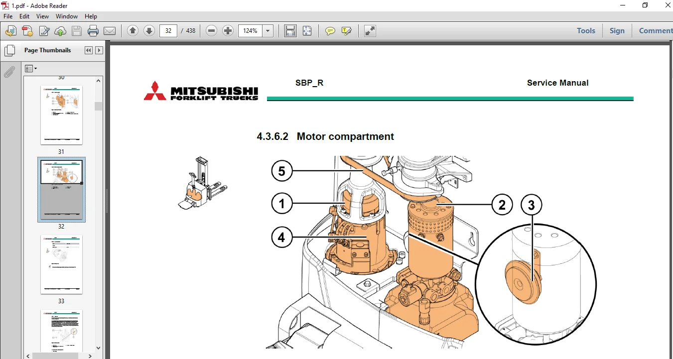
4 3 6 Motor and electrical system 30
4 3 7 Sensors 34
4 3 8 Mast unit 35
5 Mechanical maintenance 38
5 1 Lifting points 38
5 1 1 Jack points 38
5 1 2 Hoist points 39
5 2 Transportation 39
5 3 Ordering spare parts 40
5 4 Opening the covers 41
5 4 1 Front cover with controls 42
5 4 2 Battery cover 44
5 5 Removing the operator’s platform 45
5 5 1 Removing the operator’s platform rubber absorbers 48
5 5 2 Replacing the operator’s platform gas spring 49
5 5 3 Removing the operator’s platform slide bearing 51
5 6 Transmission gear 52
5 7 Bogie bearing 53
5 8 Traction wheel 53
5 8 1 Disassembly of the traction wheel 54
© Mitsubishi Forklift Trucks 2013 All rights reserved Revision: B Document ID: 616841 4 (338)
SBP_R Service Manual
5 8 2 Assembly of the traction wheel 56
5 9 Castor wheel 57
5 9 1 Adjusting the castor wheel 57
5 9 2 Disassembly of the castor wheel unit 59
5 9 3 Disassembly of the castor wheel 60
5 9 4 Assembly of the castor wheel 60
5 10 Tiller arm 61
5 10 1 Disassembly of the center steering assembly 62
5 11 Tiller arm joint 63
5 12 Mast unit 68
5 12 1 Detailed construction 68
5 12 2 Mast unit maintenance 80
5 12 3 Lubricant and fluid recommendations 81
5 12 4 Removing the mast unit 81
5 12 5 Disassembly of the mast unit 96
5 12 6 Triplex mast with free lift 123
5 12 7 Inspecting the forks 134
5 12 8 Load wheels 140
5 12 9 Mast chains 141
5 12 10 Chain yoke 150
5 12 11 Guidance rollers 152
5 12 12 Main rollers 154
5 12 13 Free lift cylinder 156
5 12 14 Side cylinders 163
5 12 15 Initial lift cylinder 173
6 Electrical operation 176
6 1 Using the schematic diagram 176
6 2 Power source 179
6 3 Safety circuit (emergency stop button) 179
6 4 Key switch 179
6 5 Traction 180
6 6 AC motor operation 180
6 7 Sensorless operation 181
7 Battery maintenance 182
7 1 Safety regulations concerning the handling of lead-acid batteries 183
7 2 Battery maintenance 184
7 2 1 Daily maintenance 184
7 2 2 Weekly maintenance 184
7 2 3 Monthly maintenance 184
7 2 4 Annual maintenance 185
7 3 Recharging the battery 185
7 4 Measuring the battery’s specific gravity 188
7 5 Replacing the battery 188
8 Electric system maintenance 191
8 1 Tiller arm 191
8 1 1 Removing the tiller head 192
© Mitsubishi Forklift Trucks 2013 All rights reserved Revision: B Document ID: 616841 5 (338)
SBP_R Service Manual
8 1 2 Removing the tiller head switches 194
8 1 3 Removing the safety button 195
8 1 4 Removing the accelerator 197
8 1 5 Installing the accelerator 199
8 1 6 Removing the controller for lifting and lowering 200
8 1 7 Installing the controller for lifting and lowering 201
8 2 Electric panel 202
8 2 1 Removing the controller cover 203
8 2 2 Traction controller 204
8 2 3 Traction controller connectors 205
8 2 4 Contactors and relays 210
8 2 5 Fuses 211
8 2 6 Accessing the controller fan 212
8 3 Truck connector 214
8 3 1 Replacing the truck connector 214
8 4 Motor compartment 215
8 4 1 Removing the drive unit 216
8 4 2 Disassembly of the drive unit 217
8 4 3 Installation of the traction motor 217
8 4 4 Assembly of the splined shaft-hub connection 218
8 4 5 Temperature sensor check 220
8 4 6 Magnetic brake 221
8 4 7 Motor belt 222
8 5 Pump motor 226
8 5 1 Solenoid valve 227
8 6 Sensors 228
8 6 1 Tiller and operator’s platform sensors 228
8 6 2 Initial lift upper limit sensor 230
8 7 Switches and buttons 231
8 7 1 Emergency stop button 231
8 7 2 Key switch 232
8 7 3 Tiller head microswitch 233
8 8 Horn 234
8 8 1 Diode test with a multimeter 234
8 9 Wiring harnesses and cables 235
8 9 1 Installing the traction motor cables 238
9 Electric system adjustments and measurements 240
9 1 Calibrating the accelerator 240
9 1 1 Acquiring the VACC with TruckTool 240
9 1 2 Acquiring the VACC without Truck Tool 241
9 2 Calibrating the controller for lifting and lowering 241
9 2 1 Acquiring the VACC with TruckTool 241
9 3 Insulation resistance test 242
9 3 1 Test voltage 242
9 3 2 Checking the insulation tester 243
9 3 3 Measuring the insulation resistance 243
10 Hydraulic operation 246
10 1 Hydraulic symbols 249
© Mitsubishi Forklift Trucks 2013 All rights reserved Revision: B Document ID: 616841 6 (338)
SBP_R Service Manual
10 2 Hydraulic oil recommendations 251
10 3 Maintenance points of the hydraulic system 251
10 4 Hydraulic aggregate 252
10 4 1 Setting the lifting pressure 252
10 4 2 Disassembly of the hydraulic aggregate 254
11 TruckTool Diagnostics 255
12 Parameter descriptions 256
12 1 Traction controller 256
13 Alarm codes 264
13 1 Traction controller 264
14 Service data 283
14 1 Special tightening torques 283
14 2 Tightening torque for standard bolts and nuts 284
14 3 Maintenance check list 286
14 4 Lubrication 289
14 4 1 Hydraulic oil 289
14 4 2 Transmission oil 289
14 5 Special tools 289
15 Options 291
15 1 Load support 292
15 1 1 Installation of the load support 292
15 1 2 Installation of the load support (masts with straddle fork) 293
15 2 Accessory rack 293
15 2 1 Installation of the accessory rack 294
15 2 2 Installation of the list bracket 295
15 2 3 Installation of the computer rack 296
15 2 4 Installation of the bottle rack 297
15 2 5 Installation of the pen rack 298
15 3 Voltage converter 299
15 3 1 Installation of the voltage converter 299
15 4 Battery connector 300
15 4 1 Replacing the battery connector 301
15 5 Charger connector 301
15 5 1 Replacing the charger connector 302
15 6 Internal charger and the internal charger connector 302
15 6 1 Installation of the internal charger and the internal charger connector 303
15 7 Abbot 305
15 7 1 Installation of the abbot 306
15 8 Hydraulic block valve 306
15 8 1 Installation of the hydraulic block valve 307
15 9 PIN code unit keyboard 308
15 9 1 Installation of the PIN code unit keyboard 308
15 9 2 Activating the truck with the PIN code 309
15 9 3 Programming a new PIN code 309
© Mitsubishi Forklift Trucks 2013 All rights reserved Revision: B Document ID: 616841 7 (338)
SBP_R Service Manual
15 9 4 Driver Present mode 310
15 10 Driving speed reduction 311
15 10 1 Driving speed reduction sensor 311
16 Technical specification 318
17 Index 328
APPENDIX A: Stickers 332
PLEASE NOTE:
- This is the same manual used by the dealers to diagnose and troubleshoot your vehicle
- You will be directed to the download page as soon as the purchase is completed. The whole payment and downloading process will take anywhere between 2-5 minutes
- Need any other service / repair / parts manual, please feel free to contact [email protected] . We still have 50,000 manuals unlisted