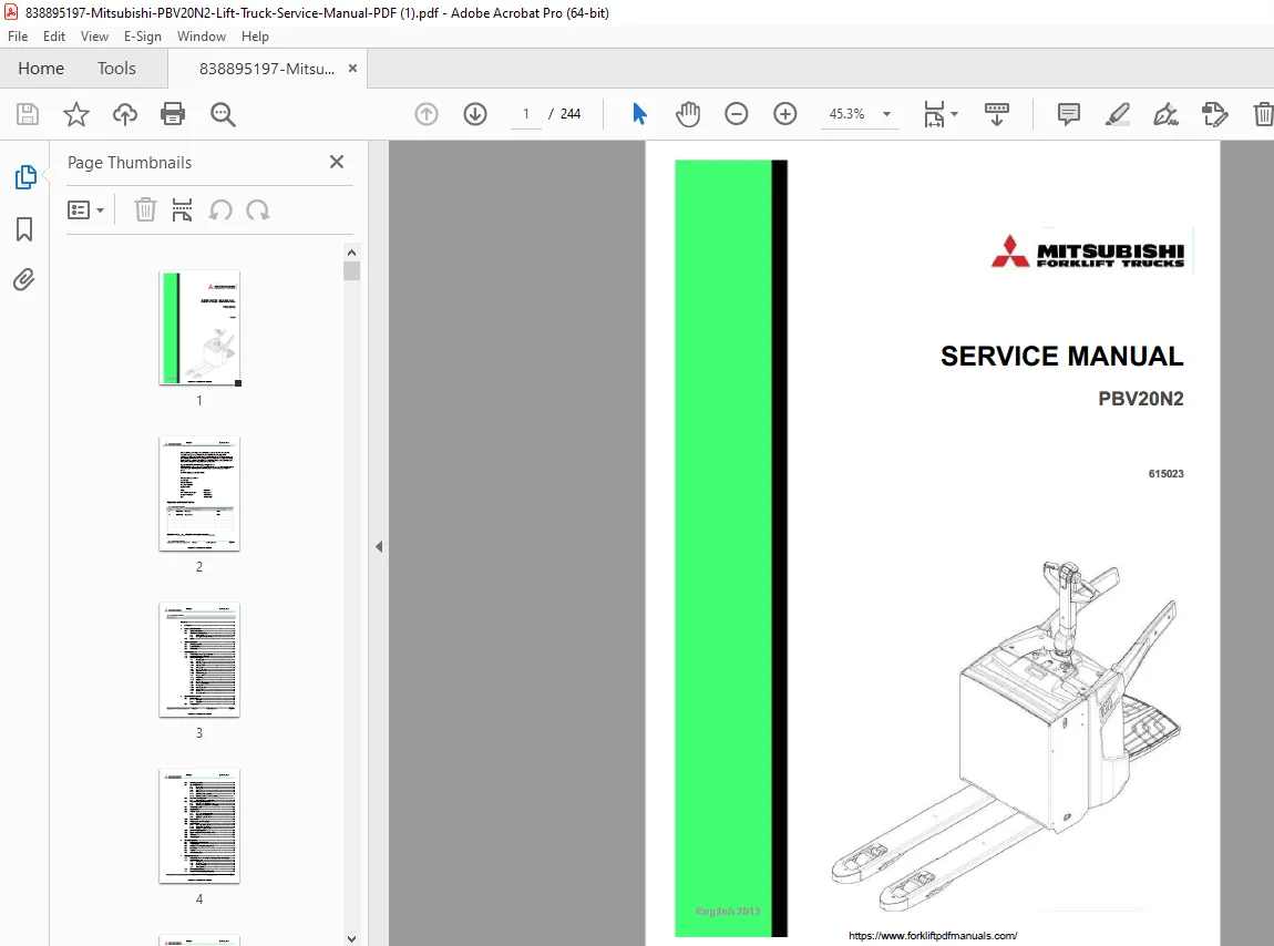
Mitsubishi PBV20N2 Lift Truck Service Manual – PDF DOWNLOAD
Original price was: $95.00.$28.95Current price is: $28.95.
Comprehensive Mitsubishi PBV20N2 service manual PDF for powered pallet trucks. Includes Mitsubishi forklift troubleshooting guide, PBV20N2 electrical system maintenance, hydraulic aggregate repair instructions, traction motor replacement procedures, and battery maintenance. Covers adjustments, diagnostics, and options like electrical steering. 244-page guide from 2013, ideal for technicians.
Description
Mitsubishi PBV20N2 Lift Truck Service Manual – PDF DOWNLOAD
Description
This official Mitsubishi PBV20N2 service manual PDF provides detailed guidance for servicing the PBV20N2 powered pallet truck, emphasizing safety, mechanical, electrical, and hydraulic maintenance. Produced by Mitsubishi Forklift Trucks in collaboration with Mitsubishi Caterpillar Forklift entities, it covers truck overview, component removal/installation, Mitsubishi forklift troubleshooting guide procedures, PBV20N2 electrical system maintenance, and hydraulic aggregate repair instructions. Key sections include traction motor replacement procedures, sensor checks, battery handling, and TruckTool diagnostics for error codes and parameters.
The manual ensures compliance with warranty terms, recommending original parts and professional service for long-term operation. It includes special tools, tightening torques, lubrication specs, and options like pallet entry rollers or electrical steering. With a focus on practical repairs, it details disassembly of drive units, calibration of accelerators, and insulation resistance tests.
Neatly Categorized Table of Contents (extracted and formatted from pages 3-7 for clarity):
- 1 Foreword (Page 8)
- 2 How to read this manual (Page 9)
- 2.1 Safety-related signs (9)
- 2.2 Symbols and abbreviations (9)
- 2.2.1 Safety symbols (9)
- 2.2.2 Other symbols and abbreviations (11)
- 2.3 Units (11)
- 3 Safety instructions (Page 12)
- 3.1 Service area safety (12)
- 3.2 Personal safety (13)
- 3.3 Work safety (13)
- 4 General information (Page 16)
- 4.1 Truck model covered by this manual (16)
- 4.2 Identification plates on the truck (16)
- 4.3 Overview of the truck (17)
- 4.3.1 Operating devices (17)
- 4.3.2 Tiller arm (18)
- 4.3.2.1 Tiller arm controls (18)
- 4.3.2.2 Tiller arm positions (19)
- 4.3.3 Control panel (20)
- 4.3.3.1 Emergency stop button (20)
- 4.3.3.2 Key switch (21)
- 4.3.3.3 Multi-function display (22)
- 4.3.4 Driving position (23)
- 4.3.4.1 Pedestrian mode (23)
- 4.3.4.2 Riding mode (24)
- 4.3.5 Driving direction (25)
- 4.3.6 Motor and electrical system (26)
- 4.3.6.1 Electric panel (27)
- 4.3.6.2 Motor compartment (28)
- 4.3.6.3 Traction motor (29)
- 4.3.7 Sensors (30)
- 4.3.8 Truck suspension (31)
- 5 Mechanical maintenance (Page 32)
- 5.1 Lifting points (32)
- 5.1.1 Jack points (32)
- 5.1.2 Hoist points (33)
- 5.2 Transportation (33)
- 5.3 Ordering spare parts (34)
- 5.4 Opening the covers (34)
- 5.4.1 Front cover (35)
- 5.4.2 Control panel (36)
- 5.4.3 Top cover (37)
- 5.4.4 Battery cover (38)
- 5.4.4.1 Removing the battery cover lock (40)
- 5.4.4.2 Removing the battery cover’s rubber absorbers (41)
- 5.5 Removing the side guards (41)
- 5.5.1 Replacing the side guard’s gas spring (42)
- 5.6 Removing the operator’s platform (44)
- 5.6.1 Replacing the operator’s platform gas spring (48)
- 5.6.2 Removing the operator’s platform slide bearing (50)
- 5.7 Transmission gear (51)
- 5.8 Bogie bearing (52)
- 5.9 Traction wheel (52)
- 5.9.1 Disassembly of the traction wheel (53)
- 5.9.1.1 Replacing the wheel shaft bolts (54)
- 5.9.2 Assembly of the traction wheel (55)
- 5.9.1 Disassembly of the traction wheel (53)
- 5.10 Load wheels (56)
- 5.11 Lifting system and fork carriage (57)
- 5.12 Castor wheels (59)
- 5.12.1 Disassembly of the castor wheel (60)
- 5.12.2 Adjusting the castor wheels (60)
- 5.12.3 Assembly of the castor wheel (61)
- 5.13 Castor wheel suspension (62)
- 5.14 Disassembly of the drive unit suspension (64)
- 5.15 Tiller arm (67)
- 5.16 Tiller arm joint (69)
- 5.1 Lifting points (32)
- 6 Electrical operation (Page 72)
- 6.1 Using the schematic diagram (72)
- 6.2 Power source (75)
- 6.3 Safety circuit (emergency stop button) (75)
- 6.4 Key switch (75)
- 6.5 Traction (76)
- 6.6 AC motor operation (76)
- 7 Battery maintenance (Page 77)
- 7.1 Safety regulations concerning the handling of lead-acid batteries (78)
- 7.2 Battery maintenance (79)
- 7.2.1 Daily maintenance (79)
- 7.2.2 Weekly maintenance (79)
- 7.2.3 Monthly maintenance (79)
- 7.2.4 Annual maintenance (79)
- 7.3 Recharging the battery (80)
- 7.4 Measuring the battery’s specific gravity (82)
- 7.5 Replacing the battery (82)
- 8 Electric system maintenance (Page 85)
- 8.1 Tiller arm (85)
- 8.1.1 Removing the tiller head (85)
- 8.1.2 Removing the tiller head switches (87)
- 8.1.3 Removing the safety button (88)
- 8.1.3.1 Installing the rubber handles (90)
- 8.1.4 Removing the accelerator (91)
- 8.1.5 Installing the accelerator (93)
- 8.2 Electric panel (94)
- 8.2.1 Removing the controller cover (95)
- 8.2.2 Zapi COMBIACX Power Controller (96)
- 8.2.3 Zapi COMBIACX connectors (96)
- 8.2.3.1 CNA external connector (97)
- 8.2.3.2 CNB external connector (98)
- 8.2.3.3 CNC external connector (99)
- 8.2.3.4 CND external connector (100)
- 8.2.3.5 Description of the power connections (101)
- 8.2.4 Contactors and relays (101)
- 8.2.5 Fuses (103)
- 8.2.6 Accessing the controller fan (104)
- 8.3 Motor compartment (106)
- 8.3.1 Removing the drive unit (107)
- 8.3.2 Disassembly of the drive unit (108)
- 8.3.3 Installation of the traction motor (109)
- 8.3.4 Assembly of the splined shaft-hub connection (110)
- 8.3.5 Temperature sensor check (111)
- 8.3.6 HALL sensor (112)
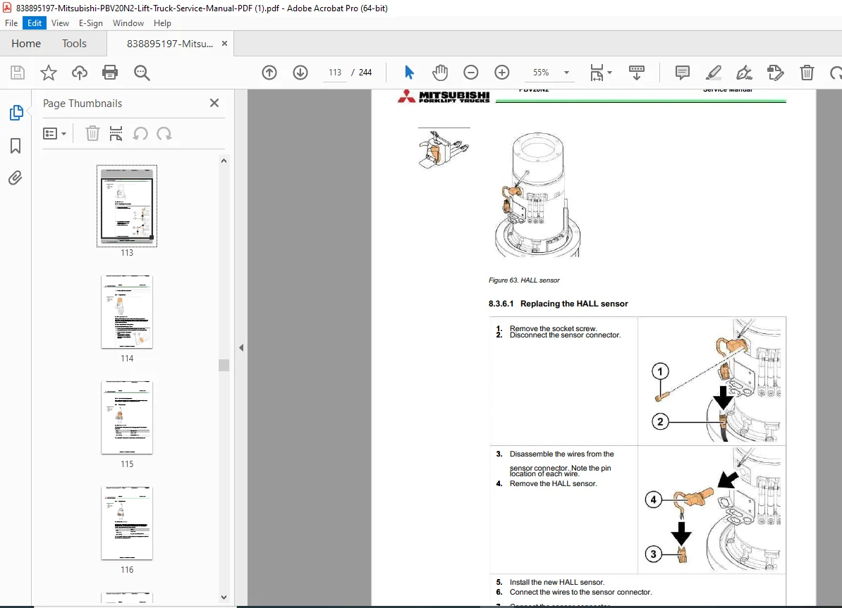
- 8.3.6.1 Replacing the HALL sensor (113)
- 8.3.7 Magnetic brake (114)
- 8.3.7.1 Coil resistance measurement (115)
- 8.4 Pump motor (115)
- 8.4.1 Solenoid valve (116)
- 8.5 Sensors (117)
- 8.5.1 Tiller, side guard and operator’s platform sensors (117)
- 8.6 Switches and buttons (120)
- 8.6.1 Emergency stop button (120)
- 8.6.2 Key switch (121)
- 8.6.3 Tiller head micro switch (122)
- 8.7 Horn (123)
- 8.7.1 Diode test with a multimeter (123)
- 8.8 Wiring harnesses and cables (124)
- 8.8.1 Installing the traction motor cables (126)
- 8.1 Tiller arm (85)
- 9 Electric system adjustments and measurements (Page 128)
- 9.1 Calibrating the accelerator (128)
- 9.1.1 Acquiring the VACC with TruckTool (128)
- 9.1.2 Acquiring the VACC without Truck Tool (129)
- 9.2 Insulation resistance test (129)
- 9.2.1 Test voltage (129)
- 9.2.2 Checking the insulation tester (130)
- 9.2.3 Measuring the insulation resistance (130)
- 9.2.3.1 Insulation resistance of the truck (131)
- 9.2.3.2 Insulation resistance of the battery (132)
- 9.1 Calibrating the accelerator (128)
- 10 Hydraulic operation (Page 133)
- 10.1 Hydraulic symbols (135)
- 10.2 Hydraulic oil recommendations (137)
- 10.3 Maintenance points of the hydraulic system (137)
- 10.4 Hydraulic aggregate (138)
- 10.4.1 Disassembly of the hydraulic aggregate (138)
- 10.4.2 Disassembly of the oil tank (139)
- 10.5 Replacing the hydraulic cylinder (140)
- 10.5.1 Replacing the hydraulic cylinder’s slide bearings (143)
- 11 TruckTool Diagnostics (Page 144)
- 12 Parameter descriptions (Page 145)
- 12.1 Traction controller (145)
- 13 Alarm codes (Page 154)
- 13.1 Traction controller (154)
- 14 Service data (Page 173)
- 14.1 Special tightening torques (173)
- 14.2 Tightening torque for standard bolts and nuts (174)
- 14.3 Maintenance check list (176)
- 14.4 Lubrication (178)
- 14.4.1 Hydraulic oil (178)
- 14.4.2 Transmission oil (178)
- 14.5 Special tools (178)
- 15 Options (Page 180)
- 15.1 Pallet entry / exit rollers (181)
- 15.1.1 Disassembly of the pallet entry / exit rollers (181)
- 15.2 Load support (182)
- 15.2.1 Installation of the load support (183)
- 15.3 Accessory rack (183)
- 15.3.1 Installation of the accessory rack (184)
- 15.3.1.1 Installation of the list bracket (185)
- 15.3.1.2 Installation of the computer rack (186)
- 15.3.1.3 Installation of the bottle rack (187)
- 15.3.1.4 Installation of the pen rack (187)
- 15.3.1.5 Installation of the working lights (188)
- 15.3.1 Installation of the accessory rack (184)
- 15.4 Lever for lifting and lowering (190)
- 15.4.1 Removing the controller for lifting and lowering (191)
- 15.4.2 Installing the controller for lifting and lowering (192)
- 15.4.3 Calibrating the controller for lifting and lowering (193)
- 15.4.3.1 Acquiring the VACC with TruckTool (193)
- 15.4.3.2 Acquiring the VACC without Truck Tool (194)
- 15.5 Voltage converter (195)
- 15.5.1 Installation of the voltage converter (195)
- 15.6 Pressure sensor (196)
- 15.6.1 Installation of the pressure sensor (197)
- 15.6.2 Pressure sensor functionality check (198)
- 15.7 Battery lock sensor (198)
- 15.7.1 Installation of the battery lock sensor (199)
- 15.7.2 Battery lock sensor functionality check (200)
- 15.8 Battery connector (200)
- 15.9 Recharging plug (200)
- 15.9.1 Replacing the recharging plug (201)
- 15.10 Quick battery replacement (203)
- 15.10.1 Removing the rubber absorbers with quick battery replacement (204)
- 15.11 Electrical steering (205)
- 15.11.1 Motor and electrical system with electrical steering (206)
- 15.11.2 Zapi EPS ACO Power Controller (208)
- 15.11.3 Zapi EPS ACO connectors (208)
- 15.11.3.1 CNA external connector (209)
- 15.11.3.2 CNB external connector (210)
- 15.11.3.1 Description of the power connections (210)
- 15.11.3.2 Fuses with electrical steering (211)
- 15.11.4 Feedback sensor (211)
- 15.11.4.1 Functionality check of the feedback sensor (212)
- 15.11.5 Disassembly of the electrical steering motor unit (213)
- 15.11.6 Adjusting the motor belt (216)
- 15.11.7 Replacing the motor belt (217)
- 15.11.8 Adjusting the electrically powered steering (217)
- 15.11.8.1 Adjusting the tiller and feedback sensors (217)
- 15.11.8.2 Feedback sensor teaching and steering angle reduction (218)
- 15.11.8.3 Tiller sensor teaching (219)
- 15.11.8.4 Steering straight forward calibration (220)
- 15.11.8.5 Final adjustment (221)
- 15.11.9 Steering controller parameter descriptions (221)
- 15.11.10 Steering controller alarm codes (223)
- 15.1 Pallet entry / exit rollers (181)
- 16 Technical specification (Page 230)
- 17 Index (Page 234)
- APPENDIX A: Stickers (Page 238)
An index is present at the end (page 234), providing alphabetical references to components and procedures. No separate bookmarks noted, but the structured TOC aids navigation. This Mitsubishi PBV20N2 service manual PDF is essential for warehouse and material handling equipment upkeep.
File Details
- Manual Name: PBV20N2 Service Manual
- Models Covered: PBV20N2
- Year: 2013
- Manual PDF Quality: High (clear text, diagrams, and illustrations)
- No of Pages: 244