Motorola CM5000 TETRA Mobile Repeater Gateway Service Manual Repair PDF
Original price was: $95.00.$18.95Current price is: $18.95.
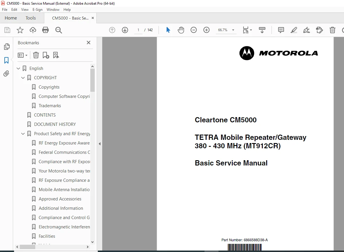
Complete factory basic service manual for the Motorola Cleartone CM5000 TETRA mobile repeater/gateway operating in 380-430 MHz band. This 142-page technical manual covers installation, adjustment, calibration, troubleshooting, and repair procedures. Includes complete circuit descriptions, test setup procedures, connector pinouts, parts lists, and exploded diagrams. Essential reference for technicians servicing TETRA digital mobile radio systems in public safety and commercial applications.
Description
Motorola CM5000 TETRA Mobile Repeater Gateway Service Manual Repair PDF DOWNLOAD
FULL DESCRIPTION
Official Factory Service Manual for Motorola CM5000 TETRA Mobile Repeater/Gateway
This comprehensive 142-page motorola cm5000 tetra mobile repeater service manual is the complete factory basic service documentation for the Motorola Cleartone CM5000 TETRA (Terrestrial Trunked Radio) mobile repeater and gateway system. Published by Motorola in January 2009 (Part Number 6866588D38-A), this manual provides detailed technical information for installation, testing, calibration, troubleshooting, and repair of these professional digital mobile radio systems.
FILE DETAILS
- Manual Name: CM5000 TETRA Mobile Repeater/Gateway Basic Service Manual
- Equipment Model: Cleartone CM5000 (Model MT912CR)
- Manual Part Number: 6866588D38-A
- Publication Date: January 2009
- System: Dimetra GR1.2 2009
- Pages: 142 pages
- Format: Professional PDF (A4 size)
- Quality: Factory original technical manual
- Language: English
- Publisher: Motorola Inc. – Global Customer Documentation (GCD-EMEA)
MOTOROLA CM5000 TETRA SYSTEM OVERVIEW
The Motorola Cleartone CM5000 is a professional-grade TETRA digital mobile repeater and gateway designed for mission-critical communications in public safety, government, transportation, and commercial applications.
Key System Features:
- TETRA digital trunked radio technology
- Operating frequency: 380-430 MHz band
- Mobile repeater and gateway functionality
- High-quality digital voice communications
- Data transmission capabilities
- GPS positioning support
- Advanced encryption options
- Dimetra system compatibility
- Ruggedized design for vehicle installation
- Professional mounting options
Primary Applications:
- Public safety communications (police, fire, EMS)
- Government agencies
- Transportation systems
- Utilities and infrastructure
- Commercial fleet management
- Security services
- Emergency response coordination
- Industrial communications
COMPREHENSIVE MANUAL COVERAGE
This cm5000 tetra gateway repair calibration guide pdf provides complete technical documentation across 6 chapters plus appendix:
CHAPTER 1: SCOPE & WARRANTY INFORMATION (Pages 1-4)
Manual Scope:
- Purpose and intended audience
- Service level covered by this manual
- Limitations and disclaimers
- Technical skill requirements
Related Documentation:
- Manuals and user guides available
- Reference document list
- Cross-reference to detailed service manual
- Installation manual references
Warranty Information:
- Motorola warranty terms
- Coverage limitations
- Service authorization requirements
- Liability disclaimers
CHAPTER 2: MODEL INFORMATION (Pages 5-8)
CM5000 Model Details:
- Complete model identification
- Part number breakdown
- Frequency band specifications
- Hardware variants
- Software versions
System Features:
- TETRA digital technology
- Repeater functionality
- Gateway capabilities
- Voice and data services
- GPS integration
- Encryption support
- Emergency calling
- Group communications
- Individual calling
- Status messaging
- Short data services (SDS)
- Packet data services
Technical Specifications:
RF Specifications:
- Frequency range: 380-430 MHz
- Channel spacing: 25 kHz
- Modulation: π/4 DQPSK
- RF power output specifications
- Receiver sensitivity
- Selectivity specifications
- Spurious emissions
- Intermodulation performance
Audio Specifications:
- Audio frequency response
- Distortion specifications
- Signal-to-noise ratio
- Audio output power
- Microphone input sensitivity
Power Requirements:
- Operating voltage range
- Current consumption (transmit/receive/standby)
- Power connector specifications
Physical Specifications:
- Dimensions (W x H x D)
- Weight specifications
- Operating temperature range
- Storage temperature range
- Humidity specifications
- Vibration resistance
- Shock resistance
Feature Specifications:
- Channel capacity
- Talk groups
- Emergency features
- Scanning capabilities
- Priority levels
- Signaling options
CHAPTER 3: OVERVIEW (Pages 9-26)
General System Architecture:
- System block diagram
- Signal flow overview
- Component interaction
- Operating modes
Digital Control Circuit:
- Microprocessor system
- Control logic architecture
- Software/firmware structure
- Memory organization
- Interface circuits
- Communication buses
- Control algorithms
Detailed Circuit Descriptions:
- Processor Section:
- Main CPU specifications
- Clock generation
- Reset circuitry
- Memory mapping
- Interface Circuits:
- Keypad interface
- Display driver
- Audio codec
- GPS interface
- Accessory interfaces
- Programming interface
- Power Management:
- Voltage regulation
- Power distribution
- Battery backup (if applicable)
- Power-on sequencing
Radio Circuit:
- RF architecture overview
- Transmitter chain
- Receiver chain
- Frequency synthesis
- Modulation/demodulation
- Signal processing
Detailed RF Sections:
- Transmitter:
- RF amplifier stages
- Power amplifier design
- Modulator circuit
- Output filtering
- Power control
- Temperature compensation
- Receiver:
- RF front end
- Mixer stages
- IF amplification
- Demodulator
- Audio recovery
- Squelch circuit
- RSSI (Received Signal Strength Indicator)
- Frequency Synthesizer:
- PLL (Phase-Locked Loop) architecture
- VCO (Voltage Controlled Oscillator) design
- Reference oscillator
- Loop filter
- Channel switching
- Antenna Switch:
- TX/RX switching mechanism
- Isolation specifications
- Switching timing
Key and Display Unit:
- Keypad matrix
- Display technology
- LED indicators
- Control interface
- User interface circuits
CHAPTER 4: TEST SETUP & ADJUSTMENT (Pages 27-40)
Typical Test Setup:
- Required test equipment list
- Test equipment specifications
- Connection diagrams
- Test fixture setup
- Safety precautions
Required Test Equipment:
- IFR 2968 TETRA Radio Test Set (or equivalent)
- RF spectrum analyzer
- RF power meter
- Frequency counter
- DC power supply
- Digital multimeter
- Oscilloscope
- RF signal generator
- Audio analyzer
- Protocol analyzer
Self-Check Procedures:
- Built-in self-test (BIST) activation
- Diagnostic mode access
- Self-test interpretation
- Error code identification
- Component verification
IFR 2968 Test Set Configuration:
- Channel and mode setting procedures
- Test set parameter configuration
- Communication protocol setup
- Call setup procedures
- Test mode activation
RX VCO Frequency Adjustment:
- VCO alignment procedure
- Frequency measurement
- Adjustment specifications
- Tolerance limits
- Verification testing
Receiver Sensitivity Confirmation:
- Sensitivity measurement procedure
- Test signal setup
- BER (Bit Error Rate) testing
- Performance criteria
- Pass/fail specifications
Transmit Power Adjustment:
- Power measurement setup
- Power control adjustment
- Power level verification
- Multiple power level settings
- Temperature compensation adjustment
- Frequency deviation adjustment
- Modulation quality verification
Receiver Adjustment:
- Squelch threshold adjustment
- AGC (Automatic Gain Control) alignment
- Discriminator alignment
- Audio level adjustment
- Selectivity verification
- Adjacent channel rejection testing
CHAPTER 5: CONNECTOR PIN FUNCTION (Pages 41-46)
Complete Connector Pinout Documentation:
Microphone Connector (Panel):
- Pin assignments
- Audio connections
- PTT (Push-To-Talk) signal
- Ground connections
- Accessory interface pins
- Voltage specifications
Accessory Connector 1:
- Pin function descriptions
- Audio input/output
- Control signals
- Programming interface
- External alarm connections
- Ignition sense
- Speaker outputs
Accessory Connector 2:
- Additional interface pins
- Emergency button input
- Status outputs
- Data connections
- Auxiliary functions
Antenna Connector:
- RF connector type
- Impedance specification (50Ω)
- VSWR requirements
- Power handling
GPS Antenna Connector:
- GPS antenna power supply
- GPS signal input
- Active antenna compatibility
- Cable specifications
Power Connector:
- Positive power input
- Ground connections
- Voltage range
- Current capacity
- Fusing requirements
- Polarity protection
CHAPTER 6: PARTS LISTS AND DRAWINGS (Pages 47-50)
Replacement Parts List:
- Complete parts catalog
- Part numbers
- Descriptions
- Quantity per unit
- Notes on availability
Accessories Replacement Parts List:
- Microphones
- Speakers
- Mounting brackets
- Cables and adapters
- Antennas
- Power supplies
- Programming cables
Diagrams:
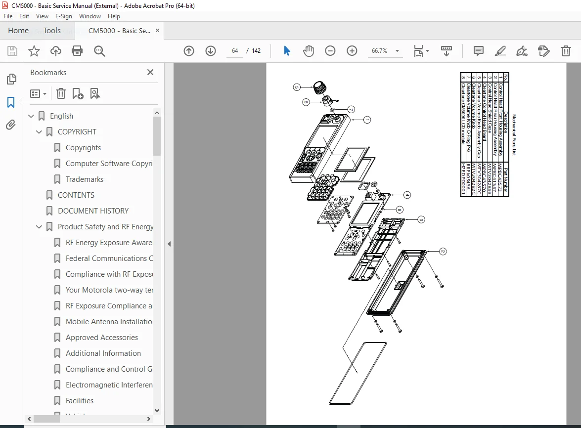
- Exploded view drawings
- Assembly diagrams
- Mechanical drawings
- Cable routing diagrams
- Mounting configurations
APPENDIX A: REPLACEMENT PARTS & KITS (Pages 51-55)
Servicing CM5000 Mobile Units:
- Service philosophy
- Field-replaceable units (FRUs)
- Board-level vs. component-level repair
- Service kit contents
- Tool requirements
Service Information by Region:
Europe, Middle East and Africa Region:
- Service center contact information
- Parts ordering procedures
- RMA (Return Merchandise Authorization) process
- Technical support contacts
Asia, Pacific Region:
- Regional service centers
- Parts distribution
- Support resources
Latin America Region:
- Service locations
- Parts availability
- Contact information
KEY FEATURES OF THIS MOTOROLA TETRA MOBILE RADIO TECHNICAL SERVICE MANUAL
✅ TETRA-Specific Technology – Specialized digital trunked radio system information
✅ Complete Test Procedures – Professional test equipment setup and calibration
✅ Detailed Circuit Descriptions – Understand RF and digital control systems
✅ Connector Documentation – Complete pinouts for all interfaces
✅ Adjustment Procedures – Restore factory specifications with precise adjustments
✅ Parts Lists – Identify replacement components with part numbers
✅ Global Service Network – Regional service center information worldwide
✅ Professional Quality – Factory-authorized technical documentation
✅ IFR Test Set Integration – Specific procedures for standard TETRA test equipment
TETRA TECHNOLOGY OVERVIEW
What is TETRA?
- Terrestrial Trunked Radio standard
- Digital PMR (Private Mobile Radio) technology
- ETSI (European Telecommunications Standards Institute) standard
- Mission-critical communications
- Efficient spectrum utilization
- Advanced features beyond analog systems
TETRA Advantages:
- Digital voice quality
- Encryption capabilities
- Fast call setup
- Group communications
- Individual addressing
- Emergency features
- Data transmission
- GPS location services
- Network coverage optimization
TEST EQUIPMENT REQUIREMENTS
Primary Test Equipment:
- IFR 2968 TETRA Radio Test Set (or equivalent):
- TETRA protocol simulation
- RF signal generation
- Audio testing
- BER measurement
- Frequency/power measurement
Additional Test Equipment:
- Spectrum analyzer (380-430 MHz capability)
- RF power meter (accurate to ±0.5 dB)
- Precision frequency counter
- Regulated DC power supply (13.6V nominal)
- True RMS digital multimeter
- Oscilloscope (100 MHz minimum bandwidth)
- Audio distortion analyzer
- TETRA protocol analyzer
ADJUSTMENT AND CALIBRATION PROCEDURES
Critical Adjustments:
Frequency Accuracy:
- Reference oscillator calibration
- VCO alignment
- Synthesizer lock verification
- Frequency stability testing
Power Output:
- Multiple power level calibration
- Power control linearity
- Temperature compensation
- ALC (Automatic Level Control) adjustment
Receiver Performance:
- Sensitivity optimization
- Squelch threshold setting
- AGC calibration
- Audio level adjustment
Modulation Quality:
- Deviation adjustment
- Modulation balance
- Spectrum compliance
- Occupied bandwidth verification
PERFECT FOR THESE PROFESSIONALS
📻 Two-Way Radio Technicians – Essential for TETRA system maintenance
🔧 Communication System Engineers – Complete technical reference
🚓 Public Safety Communication Specialists – Critical for emergency services
🏢 Fleet Communication Managers – In-house service capability
🎓 Technical Training Programs – Educational resource for digital radio technology
🛠️ Field Service Engineers – On-site repair and calibration
🏭 Industrial Communication Technicians – Maintain critical infrastructure systems
WHY THIS MANUAL IS ESSENTIAL
This cm5000 380 430 mhz repeater troubleshooting guide provides critical information:
- TETRA Expertise – Specialized knowledge for digital trunked radio systems
- Mission-Critical Systems – Proper service ensures reliable emergency communications
- Technical Accuracy – Factory procedures ensure specification compliance
- Cost Savings – In-house service reduces downtime and service costs
- Regulatory Compliance – Maintain FCC/ETSI specifications
- System Optimization – Maximize performance and coverage
- Troubleshooting Efficiency – Systematic diagnosis reduces repair time
- Parts Identification – Correct part numbers for replacement components
REGULATORY AND SAFETY INFORMATION
RF Safety Compliance:
- FCC regulations (US markets)
- RF energy exposure standards
- Occupational use requirements
- Installation guidelines
- Minimum separation distances
EMC Compliance:
- Electromagnetic compatibility requirements
- Interference mitigation
- Installation best practices
- Vehicle installation considerations
Product Safety:
- Operational warnings
- Installation precautions
- Airbag compatibility
- Explosive atmosphere restrictions
- Blasting area safety
COMMON REPAIRS COVERED
Transmitter Issues:
- Low RF power output
- Frequency deviation problems
- Spurious emissions
- Power control failures
- PA (Power Amplifier) damage
Receiver Problems:
- Poor sensitivity
- Desensitization
- Squelch malfunction
- Audio distortion
- Selectivity degradation
System Failures:
- Processor lockup
- Display problems
- Keypad malfunction
- GPS receiver failure
- Accessory interface issues
Power Supply Issues:
- Voltage regulation failure
- Power consumption problems
- Battery backup failures
MOTOROLA DIMETRA SYSTEM INTEGRATION
The CM5000 is designed for integration with Motorola’s Dimetra TETRA infrastructure:
- Network compatibility
- System registration
- Roaming capabilities
- Dispatcher integration
- Fleet management systems
- Logging and recording interfaces
TETRA APPLICATIONS
Public Safety:
- Police departments
- Fire services
- Emergency medical services
- Search and rescue operations
- Disaster response coordination
Transportation:
- Railways
- Airports
- Mass transit systems
- Port operations
- Highway maintenance
Utilities:
- Electric power utilities
- Water and wastewater
- Gas distribution
- Telecommunications
Commercial:
- Security services
- Event management
- Industrial facilities
- Oil and gas operations
- Mining operations
SERVICE LEVEL
This “Basic Service Manual” provides:
- Field-level troubleshooting
- Adjustment and calibration procedures
- Component-level identification
- Parts replacement information
- Test procedures
Note: For detailed component-level schematics and advanced troubleshooting, the “Detailed Service Manual” is available separately.
QUALITY GUARANTEE
This is a factory-original Motorola manual featuring:
- Accurate technical specifications
- Official adjustment procedures
- Motorola part numbers
- Professional diagrams and illustrations
- Compliance with industry standards
- PDF format for easy reference
- Compatible with all PDF readers
- Printable for shop use
Professional TETRA Service Information – Download Instantly!
Keep your Motorola CM5000 TETRA mobile repeater operating at peak performance! This official factory service manual provides the technical procedures and specifications needed to maintain these mission-critical digital radio systems. With complete test procedures, detailed adjustments, and comprehensive troubleshooting guides, you’ll ensure reliable communications for public safety and critical operations.
Instant digital download means you start servicing immediately – no shipping delays, no damaged paper manuals. Whether you’re a professional two-way radio technician, communication system engineer, or public safety technical specialist, this comprehensive manual is essential for proper maintenance of TETRA mobile equipment. Download now and keep your critical communications systems operational and compliant!