Trusted Business
Verified & Licensed
Virus Free Files
100% Safe Downloads
Secure Payment
SSL Protected
Instant Delivery
Available Immediately
MTU DGC-2020 DIGITAL GENSET CONTROLLER Instruction Manual PDF DOWNLOAD
$30.95
MTU DGC-2020 DIGITAL GENSET CONTROLLER Instruction Manual PDF DOWNLOAD
Instant PDF Download
Available immediately
Save to Your Device
Download & keep forever
Antivirus Scanned
100% virus-free
Trusted Worldwide
175,000+ customers
Description
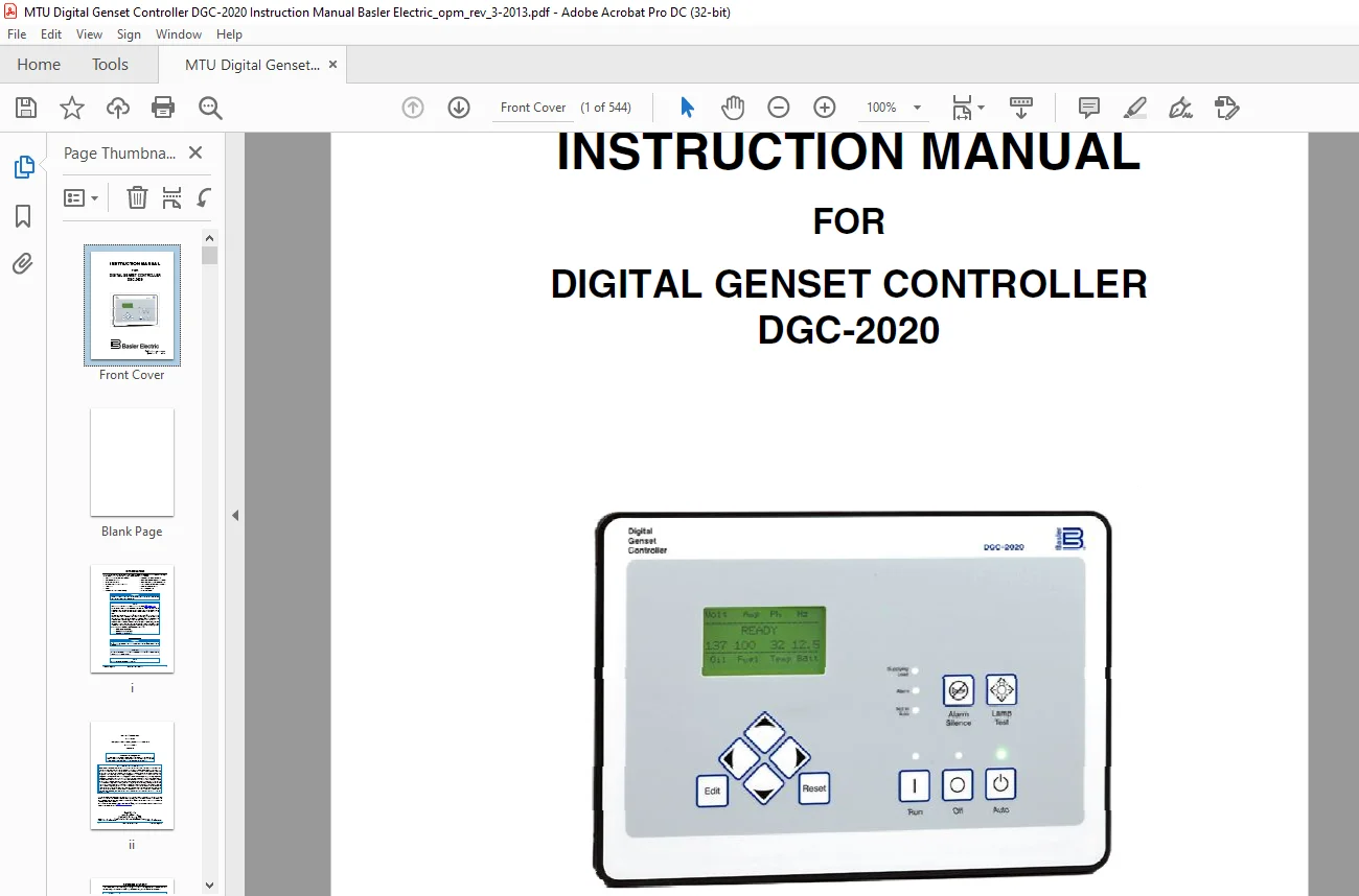
MTU DGC-2020 DIGITAL GENSET CONTROLLER Instruction Manual PDF DOWNLOAD
FILE DETAILS:
MTU DGC-2020 DIGITAL GENSET CONTROLLER Instruction Manual PDF DOWNLOAD
Language : English
Pages : 544
Downloadable : Yes
File Type : PDF
IMAGES PREVIEW OF THE MANUAL:
Need help? Contact: [email protected]
https://vimeo.com/858926658?share=copy
DESCRIPTION:
MTU DGC-2020 DIGITAL GENSET CONTROLLER Instruction Manual PDF DOWNLOAD
INTRODUCTION:
This instruction manual provides information about the operation and installation of the DGC-2020 Digital Genset Controller. To accomplish this, the following information is provided:
- General Information and Specifications
- Controls and Indicators
- Functional Description
- Graphical User Interface Operation
- Installation
- Setup
- Maintenance and Troubleshooting
- LSM-2020 (Load Share Module)
- CEM-2020 (Contact Expansion Module)
- AEM-2020 (Analog Expansion Module)
- Time Overcurrent Characteristic Curves
- Modbus™ Communication
- PID Tuning Settings
- MTU Fault Codes
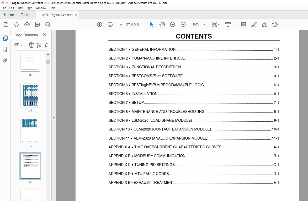
TABLE OF CONTENTS:
MTU DGC-2020 DIGITAL GENSET CONTROLLER Instruction Manual PDF DOWNLOAD
COVER
.............................................................................................................  1
INTRODUCTION
......................................................................................................  3
REVISION HISTORY
..................................................................................................  5
DETAILED FIRMWARE RELEASE HISTORY
................................................................................. 15
CONTENTS
.......................................................................................................... 17
1 • GENERAL INFORMATION
........................................................................................... 19
	Description.................................................................................................... 21
	Features....................................................................................................... 21
	Functions...................................................................................................... 21
		Generator Protection and Metering.......................................................................... 21
		Engine Protection and Metering............................................................................. 21
		Event Recording............................................................................................ 21
		Auto-Synchronizer.......................................................................................... 22
		Contact Inputs and Output Contacts......................................................................... 22
		Automatic Transfer Switch Control (Mains Failure).......................................................... 22
		Communication.............................................................................................. 22
			USB Port............................................................................................... 22
			CANbus Interface....................................................................................... 22
			Dial-Out Modem......................................................................................... 23
			RS-485 Port............................................................................................ 23
	AEM-2020 (Analog Expansion Module)............................................................................. 23
	CEM-2020 (Contact Expansion Module)............................................................................ 23
	LSM-2020 (Load Share Module)................................................................................... 23
	Style Number................................................................................................... 23
	Specifications................................................................................................. 24
		Operating Power............................................................................................ 24
			Power Consumption...................................................................................... 24
		Battery Ride Through....................................................................................... 24
		Current Sensing............................................................................................ 24
			1 Aac Current Sensing.................................................................................. 24
			5 Aac Current Sensing.................................................................................. 24
		Voltage Sensing............................................................................................ 25
		Contact Sensing............................................................................................ 25
			Terminals.............................................................................................. 25
				Programmable....................................................................................... 25
		Engine System Inputs....................................................................................... 25
			Fuel Level Sensing..................................................................................... 25
			Coolant Temperature Sensing............................................................................ 25
			Oil Pressure Sensing................................................................................... 26
			Engine Speed Sensing................................................................................... 26
				Magnetic Pickup.................................................................................... 26
				Generator Voltage.................................................................................. 26
		Output Contacts............................................................................................ 26
			PRESTART, START, and RUN Relays........................................................................ 26
			Programmable Relays (12)............................................................................... 26
				Terminals(......................................................................................... 26
		Metering................................................................................................... 26
			Generator and Bus Voltage (rms)........................................................................ 26
			Generator Current (rms)................................................................................ 27
			Generator and Bus Frequency............................................................................ 27
			Apparent Power......................................................................................... 27
				Measurement/Calculation Methods.................................................................... 27
			Power Factor........................................................................................... 27
			Real Power............................................................................................. 27
				Measurement/Calculation Methods.................................................................... 27
			Oil Pressure........................................................................................... 28
			Coolant Temperature.................................................................................... 28
			Battery Voltage........................................................................................ 28
			Engine RPM............................................................................................. 28
			Engine Run Time........................................................................................ 28
			Maintenance Timer...................................................................................... 28
			Fuel Level............................................................................................. 28
		Generator Protection Functions............................................................................. 28
			Overvoltage (59) and Undervoltage (27)................................................................. 28
			Underfrequency (81U) and Overfrequency (81O)........................................................... 28
			Reverse Power (32)..................................................................................... 29
			Loss of Excitation (40Q)............................................................................... 29
			Overcurrent (51) (Optional)............................................................................ 29
			Phase Imbalance (47) (Optional)........................................................................ 29
			ROCOF (Rate of Change of Frequency) (81) (Optional).................................................... 29
			Vector Shift (78) (Optional)........................................................................... 29
		Logic Timers............................................................................................... 29
		Communication Interface.................................................................................... 29
			USB.................................................................................................... 29
			RS-485 (Optional)...................................................................................... 29
			RDP-110................................................................................................ 30
			CANbus................................................................................................. 30
			Modem (Optional)....................................................................................... 30
		Real-Time Clock............................................................................................ 30
			Clock Holdup........................................................................................... 30
		LCD Heater................................................................................................. 31
		Type Tests................................................................................................. 31
			Shock.................................................................................................. 31
			Vibration.............................................................................................. 31
			Radio Interference..................................................................................... 31
			HALT (Highly Accelerated Life Testing)................................................................. 31
			Ignition System........................................................................................ 31
		Environment................................................................................................ 31
		UL Recognition............................................................................................. 31
		CSA Certification.......................................................................................... 32
		NFPA Compliance............................................................................................ 32
		CE Compliance.............................................................................................. 32
		Physical................................................................................................... 32
2 • HUMAN-MACHINE INTERFACE
....................................................................................... 33
	Introduction................................................................................................... 35
	Front Panel.................................................................................................... 35
	Display Operation.............................................................................................. 36
		Login and Permissions...................................................................................... 36
			Login.................................................................................................. 36
			Permissions............................................................................................ 37
		Summary Screen and Configurable Metering................................................................... 37
		Sleep Mode................................................................................................. 38
		Changing a Setting......................................................................................... 38
		Front Panel Display Structure.............................................................................. 38
		Generator Network Status Display........................................................................... 58
	Rear Panel..................................................................................................... 59
3 • FUNCTIONAL DESCRIPTION
........................................................................................ 61
	Introduction................................................................................................... 63
	DGC-2020 Function Blocks....................................................................................... 63
		Power Supply............................................................................................... 63
			Battery Voltage Sensing................................................................................ 63
		Microprocessor............................................................................................. 63
			Zero Crossing Detection................................................................................ 64
			Analog-to-Digital Converter............................................................................ 64
			Watchdog Timer......................................................................................... 64
		Generator Voltage Sensing Inputs........................................................................... 64
		Bus Voltage Sensing Inputs................................................................................. 64
		Current Sensing Inputs..................................................................................... 64
		Analog Engine Sender Inputs................................................................................ 64
			Oil Pressure........................................................................................... 64
			Coolant Temperature.................................................................................... 64
			Fuel Level............................................................................................. 65
		Speed Signal Inputs........................................................................................ 65
			Generator Voltage Sensing Input........................................................................ 65
			Magnetic Pickup Input (MPU)............................................................................ 65
		Contact Inputs............................................................................................. 65
			Emergency Stop Input................................................................................... 65
			Programmable Inputs.................................................................................... 65
		Front Panel HMI............................................................................................ 66
			LCD.................................................................................................... 66
			LED Indicators......................................................................................... 66
			Pushbuttons............................................................................................ 66
		Remote Display Panel (Optional)............................................................................ 66
		Communication Ports........................................................................................ 67
			USB.................................................................................................... 67
			CANbus................................................................................................. 67
			Diagnostic Trouble Codes (DTCs)........................................................................ 70
			MTU Fault Codes........................................................................................ 77
			RS-485 (Optional)...................................................................................... 77
			Modem (Optional)....................................................................................... 77
		Output Contacts............................................................................................ 77
			PRESTART............................................................................................... 78
			START.................................................................................................. 78
			RUN.................................................................................................... 78
			Programmable........................................................................................... 78
	Modes of Operation............................................................................................. 78
		OFF........................................................................................................ 78
		RUN........................................................................................................ 78
		AUTO....................................................................................................... 78
			ATS Contact Input...................................................................................... 78
			Generator Exerciser.................................................................................... 78
			Mains Fail Transfer Functionality...................................................................... 79
			Run with Load Logic Element............................................................................ 79
			Engine Run Logic Element............................................................................... 79
			Demand Start/Stop Function............................................................................. 79
			Interoperability of the Run with Load Logic Element and the Demand Start/Stop Function................. 79
	Breaker Management............................................................................................. 79
		Introduction............................................................................................... 79
		Determining Breaker Status................................................................................. 79
		Processing Breaker Requests................................................................................ 79
			RUN Mode............................................................................................... 80
			OFF or AUTO Mode (Not Running)......................................................................... 80
			AUTO Mode (Running).................................................................................... 80
		Breaker Operation.......................................................................................... 80
			Determining if it is Acceptable to Close a Breaker..................................................... 80
			Changing the Breaker State............................................................................. 80
		Synchronizer Operation..................................................................................... 80
	Dead Bus Breaker Close Arbitration............................................................................. 82
	Event Recording................................................................................................ 83
4 • BESTCOMSPlus® SOFTWARE
........................................................................................ 89
	Introduction................................................................................................... 95
	Installation................................................................................................... 95
		Installing BESTCOMSPlus®................................................................................... 96
	Activate the DGC-2020 Plugin for BESTCOMSPlus®................................................................. 96
		Connect a USB Cable........................................................................................ 96
		Start BESTCOMSPlus® and Activate DGC-2020 Plugin Automatically............................................. 96
			Installing the USB Driver if Automatic Installation Fails.............................................. 98
		Manual Activation of the DGC-2020 Plugin................................................................... 99
			Requesting an Activation Key........................................................................... 99
			Entering an Activation Key............................................................................. 99
	Communication.................................................................................................. 99
		Modem Communication (Optional)............................................................................. 99
		Ethernet Communication..................................................................................... 99
			Configure LSM-2020 Network Settings through Device Discovery in BESTCOMSPlus........................... 99
			Configure LSM-2020 Network Settings through the Front Panel of the DGC-2020............................101
			Alternate Method to Configure LSM-2020 Network Settings through the DGC-2020...........................102
		Establishing Communication.................................................................................103
		Advanced Properties........................................................................................104
	Menu Bars......................................................................................................104
		Upper Menu Bar (BESTCOMSPlus® Shell).......................................................................104
		Lower Menu Bar (DGC-2020 Plugin)...........................................................................105
	Settings Explorer..............................................................................................106
	DGC-2020 and System Parameters.................................................................................106
	General Settings...............................................................................................107
		Front Panel HMI............................................................................................107
		Style Number...............................................................................................108
		Device Info................................................................................................108
			DGC-2020...............................................................................................108
			Load Share Module......................................................................................108
			Contact Expansion Module...............................................................................108
			Analog Expansion Module................................................................................109
		Device Security Setup......................................................................................111
			Changing Passwords.....................................................................................111
			Saving Passwords in a DGC-2020 Settings File...........................................................112
			Loading Passwords from a Settings File into the DGC-2020...............................................113
		Clock Setup................................................................................................114
			Clock Not Set Warning..................................................................................114
	Communications.................................................................................................115
		CANbus Setup...............................................................................................115
			ECU Limitations........................................................................................115
			The DGC-2020 Solution..................................................................................116
		ECU Setup..................................................................................................116
			Volvo Penta............................................................................................117
			Cummins................................................................................................118
			Diesel Particulate Filter (DPF)........................................................................118
			Speed Setup............................................................................................118
			MTU....................................................................................................118
		Voltage Regulator Setup....................................................................................121
		Modem Setup (Optional).....................................................................................121
			Dial-Out...............................................................................................122
			Dial-In................................................................................................122
			Modem Setup through the Front Panel HMI................................................................123
		RS485 Setup (Optional).....................................................................................123
	System Parameters..............................................................................................124
		System Settings and Rated Data.............................................................................124
			Genset Electrical Parameters...........................................................................124
			Engine Speed Measurement...............................................................................124
			EPS Threshold..........................................................................................125
			Measurement/Metering Units.............................................................................125
			Battery Voltage........................................................................................125
			NFPA Compliance Level..................................................................................125
			Fuel Level Function....................................................................................125
			Power Up Delay.........................................................................................125
			Generator Frequency....................................................................................125
			Calculated Rated Data..................................................................................125
		Remote Module Setup........................................................................................127
			Load Sharing Module....................................................................................127
			Contact Expansion Module...............................................................................127
			Analog Expansion Module................................................................................127
		Crank Settings.............................................................................................128
			Engine Cooldown........................................................................................128
			Off Mode Cooldown......................................................................................128
			Restart................................................................................................129
		Automatic Restart..........................................................................................130
		Exercise Timer.............................................................................................130
		Sensing Transformers.......................................................................................131
			Generator PT Settings..................................................................................131
			Bus Transformer Settings...............................................................................131
			Generator CT Settings..................................................................................131
		Relay Control..............................................................................................132
		Auto Config Detection......................................................................................133
	Programmable Inputs............................................................................................133
		Contact Inputs.............................................................................................134
		Programmable Functions.....................................................................................134
		Remote LSM Inputs..........................................................................................136
		Remote Contact Inputs......................................................................................136
		Remote Analog Inputs.......................................................................................137
		Remote RTD Inputs..........................................................................................138
		Remote Thermocouple Inputs.................................................................................139
	Programmable Outputs...........................................................................................140
		Contact Outputs............................................................................................140
		Configurable Elements......................................................................................141
		Remote Contact Outputs.....................................................................................141
		Remote Analog Outputs......................................................................................142
	Configurable Protection........................................................................................143
		Configurable Protection Scale Factors......................................................................144
	Alarm Configuration............................................................................................145
		Horn Configuration.........................................................................................145
			Horn...................................................................................................145
			Not In Auto Horn Enable................................................................................145
		Pre-Alarms.................................................................................................145
			High Fuel Level........................................................................................146
			Low Battery Voltage....................................................................................146
			Weak Battery Voltage...................................................................................146
			Battery Overvoltage....................................................................................146
			Maintenance Interval...................................................................................146
			Engine kW Overload.....................................................................................146
			Low Fuel Level.........................................................................................147
			High Coolant Temp......................................................................................147
			Low Coolant Temp.......................................................................................147
			Low Coolant Level......................................................................................147
			Low Oil Pressure.......................................................................................147
			ECU Coms Fail..........................................................................................147
			Active DTC.............................................................................................147
			AVR Bias Output Limit..................................................................................147
			GOV Bias Output Limit..................................................................................147
			Intergenset Comm Failure...............................................................................147
			LSM Comm Failure.......................................................................................148
			ID Missing.............................................................................................148
			ID Repeat..............................................................................................148
			CEM Comm Failure.......................................................................................148
			AEM Comm Failure.......................................................................................148
			Checksum Failure.......................................................................................148
			Synchronizer Failure...................................................................................148
			Breaker Close Failure..................................................................................149
			Breaker Open Failure...................................................................................149
			Reverse Rotation.......................................................................................149
			Rated Data and Per Unit Values.........................................................................149
		Alarms.....................................................................................................151
			High Coolant Temperature...............................................................................151
			Low Oil Pressure.......................................................................................152
			Overspeed..............................................................................................152
			Low Fuel Level.........................................................................................152
			Low Coolant Level......................................................................................152
		Sender Fail................................................................................................152
	Generator Protection...........................................................................................153
		Voltage Protection (27, 59, 47)............................................................................153
			Undervoltage (27-1, 27-2)..............................................................................154
			Overvoltage (59-1, 59-2)...............................................................................155
			Phase Imbalance (47)...................................................................................156
		Frequency Protection (81O/U)...............................................................................157
			Underfrequency (81U)...................................................................................157
			Overfrequency (81O)....................................................................................157
			Alternate Frequency Scale Factor.......................................................................157
			Per Unit...............................................................................................158
		Reverse Power Protection (32R).............................................................................158
		Loss of Excitation Protection (40Q)........................................................................159
		Overcurrent Protection (51-1, 51-2, 51-3)..................................................................161
			Programmable Curves for Overcurrent Protection.........................................................162
			Setting Programmable (P) Curves........................................................................162
		Loss of Mains Protection...................................................................................163
			Vector Shift (78)......................................................................................164
			ROCOF (81).............................................................................................164
	Breaker Management.............................................................................................165
		Breaker Hardware...........................................................................................165
			Start up Synchronization...............................................................................166
		Mains Failure..............................................................................................167
		Bus Condition Detection....................................................................................169
			Generator Sensing......................................................................................169
			Bus Sensing............................................................................................170
		Automatic Synchronizer (Optional)..........................................................................173
			Frequency Correction...................................................................................173
			Voltage Correction.....................................................................................173
			Synchronization Failure................................................................................174
			Gain Settings..........................................................................................174
	Bias Control Settings..........................................................................................175
		AVR Bias Control Settings..................................................................................175
			var/PF Control.........................................................................................175
		Governor Bias Control Settings.............................................................................177
			kW Control - Real Power Control Settings...............................................................177
	Multigen Management............................................................................................179
		AVR Output.................................................................................................179
		Governor Output............................................................................................180
		Load Share Output..........................................................................................180
		Demand Start/Stop..........................................................................................180
		Generator Sequencing.......................................................................................181
			Disabled...............................................................................................181
			Staggered Service Time.................................................................................181
			Balanced Service Time..................................................................................182
			Largest Size First.....................................................................................182
			Smallest Size First....................................................................................182
			Smallest Unit ID.......................................................................................182
			Adopt System Mode......................................................................................182
		Network Configuration......................................................................................183
	Programmable Senders...........................................................................................183
	BESTlogic™Plus Programmable Logic..............................................................................184
		Logic Timers...............................................................................................184
	Settings File Management.......................................................................................184
		Opening a Settings File....................................................................................185
		Saving a Settings File.....................................................................................185
		Upload Settings and/or Logic to Device.....................................................................185
		Download Settings and Logic from Device....................................................................185
		Printing a Settings File...................................................................................185
		Comparing Settings Files...................................................................................185
	Upgrading Firmware in the DGC-2020 and Expansion Modules.......................................................186
		Upgrading Firmware in Expansion Modules....................................................................187
		Upgrading Firmware in the DGC-2020.........................................................................189
	Metering Explorer..............................................................................................190
		Engine.....................................................................................................192
		Generator..................................................................................................192
		Power......................................................................................................192
		Bias Control...............................................................................................193
		Run Statistics.............................................................................................193
		Status.....................................................................................................194
		Inputs.....................................................................................................194
			Contact Inputs.........................................................................................194
			Remote LSM Inputs......................................................................................195
			Remote Contact Inputs..................................................................................195
			Remote Analog Inputs...................................................................................195
			Remote RTD Inputs......................................................................................196
			Remote Thermocouple Inputs.............................................................................196
			Remote Analog Input Values.............................................................................196
		Logic Control Relays.......................................................................................198
			Logic Control Relays...................................................................................198
		Outputs....................................................................................................198
			Contact Outputs........................................................................................198
			Configurable Elements..................................................................................199
			Remote Contact Outputs.................................................................................199
			Remote Analog Outputs..................................................................................200
		Configurable Protection....................................................................................200
		Alarms.....................................................................................................201
		Event Log..................................................................................................201
		J1939 ECU..................................................................................................203
			ECU Data...............................................................................................203
			Engine Configuration...................................................................................203
			Active DTC and Previously Active DTC...................................................................204
		MTU........................................................................................................204
			MTU Alarms.............................................................................................204
			MTU Fault Codes........................................................................................205
			MTU Status.............................................................................................205
			MTU Engine Status......................................................................................206
		Summary....................................................................................................206
		Control....................................................................................................207
		Real Time Clock............................................................................................207
		Generator Network Status...................................................................................208
		Generator Sequencing.......................................................................................208
	BESTCOMSPlus® Updates..........................................................................................208
	Auto Export Metering...........................................................................................209
5 • BESTlogic™Plus PROGRAMMABLE LOGIC  ............................................................................211
	Introduction...................................................................................................213
	Overview of BESTlogic™Plus.....................................................................................213
		BESTlogic™Plus Composition.................................................................................214
			I/O....................................................................................................214
			Components.............................................................................................228
			Elements...............................................................................................230
	Logic Schemes..................................................................................................240
		The Active Logic Scheme....................................................................................240
		Copying and Renaming Preprogrammed Logic Schemes...........................................................240
		Sending and Retrieving Logic Schemes.......................................................................240
			Retrieving a Logic Scheme from the DGC-2020............................................................240
			Sending a Logic Scheme to the DGC-2020.................................................................241
	Programming BESTlogic™Plus.....................................................................................241
		Pickup and Dropout Timers..................................................................................242
	BESTlogic™Plus File Management.................................................................................242
		Saving a BESTlogicPlus File................................................................................243
		Opening a BESTlogicPlus File...............................................................................243
		Protecting a BESTlogicPlus File............................................................................243
		Uploading a BESTlogicPlus File.............................................................................243
		Downloading a BESTlogicPlus File...........................................................................243
		Printing a BESTlogicPlus File..............................................................................243
		Clearing the On-Screen Logic Diagram.......................................................................243
	BESTlogic™Plus Examples........................................................................................243
		Example 1 - AVR Logic Block Connections....................................................................243
		Example 2 - AND Gate Connections...........................................................................244
		Example 3 - Multiple Logic Connections.....................................................................244
6 • INSTALLATION
..................................................................................................245
	General........................................................................................................247
	Product Registration...........................................................................................247
	Hardware.......................................................................................................247
	Mounting.......................................................................................................247
	Connections....................................................................................................249
		Terminations...............................................................................................249
			Operating Power........................................................................................249
			Generator Current Sensing..............................................................................249
			Generator Voltage Sensing..............................................................................250
			Bus Voltage Sensing....................................................................................250
			Analog Engine Sender Inputs............................................................................250
			Emergency Stop Input...................................................................................251
				Optional ESTOP Wiring Method.......................................................................252
			Magnetic Pickup Input..................................................................................253
			Contact Sensing Inputs.................................................................................253
			Output Contacts........................................................................................254
			USB Interface..........................................................................................254
			RS-485 Communication Port..............................................................................255
			CANbus Interface.......................................................................................255
			Dial-Out Modem.........................................................................................256
			RDP-110 Connections....................................................................................256
		Connections for Typical Applications.......................................................................257
			3-Phase Wye Connections for Typical Applications.......................................................258
			3-Phase Delta Connections for Typical Applications.....................................................259
			Single-Phase A-B Connections for Typical Applications..................................................260
			Single-Phase A-C Connections for Typical Applications..................................................261
		Connections with AEM-2020, CEM-2020, and LSM-2020..........................................................262
	Installation for CE Systems....................................................................................262
	Installation in a Salt Fog Environment.........................................................................262
7 • SETUP
.........................................................................................................263
	Introduction...................................................................................................265
	DGC-2020 Initial Setup.........................................................................................265
		Initial Setup Required to Operate Unit.....................................................................265
			General Settings.......................................................................................265
				Style Number.......................................................................................265
			Communications.........................................................................................266
				CANbus Setup (Figure 7-2)..........................................................................266
				ECU Setup (Figure 7-3).............................................................................267
			System Parameters......................................................................................267
				System Settings (Figure 7-4).......................................................................267
				Rated Data (Figure 7-5) Note: Click the Edit button to change settings.............................268
				Remote Module Setup (Figure 7-6)...................................................................269
				Crank Settings (Figure 7-7)........................................................................269
				Sensing Transformers (Figure 7-8) Note: Click the Rated Data button to make changes................270
			Relay Control..........................................................................................271
			Auto Config Detection..................................................................................272
			Alarm Configuration....................................................................................272
				Horn Configuration (Figure 7-11)...................................................................272
				Pre-Alarms.........................................................................................272
				Alarms.............................................................................................275
				Sender Fail........................................................................................275
			Programmable Senders...................................................................................276
				Coolant Temperature (Figure 7-15)..................................................................276
				Oil Pressure (Figure 7-16).........................................................................277
				Percent Fuel Level (Figure 7-17)...................................................................278
		Initial Setup (Optional)...................................................................................279
			General Settings.......................................................................................279
				Front Panel HMI (Figure 7-18)......................................................................279
				Device Security Setup..............................................................................280
				Clock Setup........................................................................................281
	Setting Up DGC-2020 Programmable Inputs and Outputs............................................................281
		Enable LSM-2020, CEM-2020, and AEM-2020....................................................................282
		Programmable Inputs........................................................................................282
			Configuration Instructions.............................................................................282
				Configuring contact inputs on the DGC-2020 (See Figure 7-22.)......................................282
				Configurable Programmable Functions on the DGC-2020 (See Figure 7-23)..............................284
				Configuring Remote LSM Inputs on the LSM-2020 (Load Share Module)..................................287
				Configuring Remote Contact Inputs on the CEM-2020 (See Figure 7-25)................................288
				Configuring Remote Analog Inputs on the AEM-2020...................................................289
				Configuring Remote RTD Inputs on the AEM-2020......................................................291
				Configuring Remote Thermocouple Inputs on the AEM-2020.............................................292
		Programmable Outputs.......................................................................................293
			Configuring Contact Outputs on the DGC-2020............................................................293
				Programmable Contact Outputs (See Figure 7-29).....................................................293
				Run Relay, Pre-Start Relay, and Start Relay........................................................293
			Setting Up Configurable Elements in the DGC-2020.......................................................294
			Configuring Remote Contact Outputs on the CEM-2020 (See Figure 7-34)...................................296
			Configuring Remote Analog Outputs on the AEM-2020......................................................296
	Generator and Bus Breaker Control..............................................................................297
		Steps Required to Configure a DGC-2020 for Generator Breaker Control.......................................298
	Synchronizer...................................................................................................302
		Steps Required to Configure a DGC-2020 Automatic Synchronizer..............................................302
	Setting up a DGC-2020 and LSM-2020 for a Load Sharing and kW Control Application...............................314
		Load Sharing Overview and Theory of Operation in the DGC-2020..............................................314
		kvar Control Overview and Theory of Operation in the DGC-2020..............................................316
		Setup of the DGC-2020 and the LSM-2020 for Load Sharing and/or kW Control..................................316
			Step by Step Setup Procedures..........................................................................317
	Mains Fail Transfer............................................................................................329
		Steps Required to Configure a DGC-2020 for Mains Fail Transfer.............................................329
8 • MAINTENANCE AND TROUBLESHOOTING
...............................................................................335
	Maintenance....................................................................................................337
		Backup Battery for the Real Time Clock.....................................................................337
	Troubleshooting................................................................................................337
		Communications.............................................................................................337
			Ethernet Port Does Not Operate Properly................................................................337
			USB Port Does Not Operate Properly.....................................................................338
			CANbus Communication Does Not Operate Properly.........................................................338
		Inputs and Outputs.........................................................................................338
			Programmable Inputs Do Not Operate as Expected.........................................................338
			Programmable Outputs Do Not Operate as Expected........................................................338
		Metering/Display...........................................................................................338
			Incorrect Display of Battery Voltage, Coolant Temperature, Oil Pressure, or Fuel Level.................338
			Incorrect Display of Generator Voltage.................................................................338
			Incorrect Measurement or Display of Generator Current..................................................339
			Incorrect Display of Engine RPM........................................................................339
			DGC-2020 Indicates Incorrect Power Factor..............................................................339
			LCD is Blank and all LEDs are Flashing at Approximately 2 Second Intervals.............................339
		Generator Breaker and Mains Breaker........................................................................339
			Generator Breaker Will Not Close to a Dead Bus.........................................................339
			Generator Breaker Will Not Close to a Live Bus.........................................................340
			Generator Breaker Does Not Open When It Should.........................................................341
			Mains Breaker Does Not Open When Mains Fails...........................................................341
			Mains Breaker Does Not Close After Mains Returns.......................................................342
		Synchronizer...............................................................................................342
			Determining if the Synchronizer is Active..............................................................342
			Synchronizer Not Active................................................................................342
			Synchronizer Active for a Short Time, Then Stops.......................................................343
			Synchronizer Does Not Lower Engine Speed Allowing Alignment of Bus and Generator.......................343
			Synchronizer Does Not Raise Engine Speed Allowing Alignment of Bus and Generator.......................343
			Synchronizer Does Not Lower the Generator Voltage to Achieve Matching of Bus and Generator Voltages....343
			Synchronizer Does Not Raise Generator Voltage to Achieve Matching of Bus and Generator Voltages........343
		Speed Bias.................................................................................................343
			Engine Speed Does Not Change When Speed Bias Voltage Changes...........................................343
			Engine Speed Decreases When Speed Bias is Increased....................................................343
			Engine Speed Increases When Speed Bias is Decreased....................................................343
		Voltage Bias...............................................................................................343
			Generator Voltage Does Not Change When Voltage Bias Changes............................................343
			Generator Voltage Decreases When AVR Speed Bias is Increased...........................................344
			Generator Voltage Increases When Speed Bias is Decreased...............................................344
		Load Sharing...............................................................................................344
			Generator Breaker Status is not being received by the DGC-2020.........................................344
			Generator Runs at Incorrect Speed when Generator Breaker is Closed.....................................344
			Generators Do Not Share Load Equally...................................................................345
			Load Sharing Works Correctly, but a Single Unit Slows Down.............................................345
		DGC-2020 Front Panel Debug Screens.........................................................................346
			LOAD SHARE DEBUG.......................................................................................346
			CONTROL DEBUG..........................................................................................347
			CEM DEBUG..............................................................................................349
			AEM DEBUG..............................................................................................350
9 • LSM-2020 (LOAD SHARE MODULE)
..................................................................................351
	General Information............................................................................................353
	Features.......................................................................................................353
	Specifications.................................................................................................353
		Operating Power............................................................................................353
		Analog Inputs..............................................................................................353
			Burden.................................................................................................353
		Analog Outputs.............................................................................................353
			Voltage Regulator Bias Output..........................................................................353
			Governor Bias Output...................................................................................353
			Load Share Line Output.................................................................................354
		Communication Interface....................................................................................354
			CAN....................................................................................................354
			Ethernet...............................................................................................354
		Type Tests.................................................................................................354
			Shock..................................................................................................354
			Vibration..............................................................................................354
			Ignition System........................................................................................354
			HALT (Highly Accelerated Life Testing).................................................................354
		Environment................................................................................................354
		UL Approval................................................................................................354
		CSA Certification..........................................................................................354
		NFPA Compliance............................................................................................355
		CE Compliance..............................................................................................355
		Physical...................................................................................................355
	Functional Description.........................................................................................355
		Analog Inputs..............................................................................................355
		Analog Outputs.............................................................................................355
			Output for Voltage Regulator Control...................................................................355
			Output for Governor Control............................................................................355
			Load Share Line Output.................................................................................355
		Generator Sequencing.......................................................................................355
		Communications.............................................................................................355
			CAN....................................................................................................355
			Ethernet Port..........................................................................................356
	BESTCOMSPlus® Software.........................................................................................356
		LSM-2020 Plugin for BESTCOMSPlus®..........................................................................356
			Device Info............................................................................................356
			Device Security Setup..................................................................................357
	Installation...................................................................................................357
		Product Registration.......................................................................................357
		Mounting...................................................................................................358
		Connections................................................................................................358
			Terminations...........................................................................................358
			Operating Power........................................................................................359
			Analog Inputs..........................................................................................359
			Analog Outputs.........................................................................................360
			CAN Interface..........................................................................................360
			Ethernet Port..........................................................................................362
		Connections for Typical Applications.......................................................................362
		Connections using AVR’, GOV’, and LS’......................................................................364
	Application....................................................................................................364
		Interfacing an External Control Device with a DGC-2020 – LSM-2020 System...................................364
			Method 1...............................................................................................364
			Method 2...............................................................................................365
	Maintenance....................................................................................................366
10 • CEM-2020 (CONTACT EXPANSION MODULE)
..........................................................................367
	General Information............................................................................................369
	Features.......................................................................................................369
	Specifications.................................................................................................369
		Operating Power............................................................................................369
		Contact Inputs.............................................................................................369
		Contact Outputs............................................................................................369
		Communication Interface....................................................................................369
			CANbus.................................................................................................369
		Type Tests.................................................................................................369
			Shock..................................................................................................369
			Vibration..............................................................................................370
			Ignition System........................................................................................370
			HALT (Highly Accelerated Life Testing).................................................................370
		Environment................................................................................................370
		UL Approval (CEM-2020 Only)................................................................................370
		UL Approval (CEM-2020H Only)...............................................................................370
		CSA Certification..........................................................................................370
		NFPA Compliance............................................................................................370
		CE Compliance..............................................................................................370
		Physical...................................................................................................370
	Functional Description.........................................................................................371
		Contact Inputs.............................................................................................371
		Contact Outputs............................................................................................371
			CEM-2020...............................................................................................371
			CEM-2020H..............................................................................................371
		Communications.............................................................................................371
			CANbus.................................................................................................371
	BESTCOMSPlus® Software.........................................................................................371
	Installation...................................................................................................371
		Product Registration.......................................................................................371
		Mounting...................................................................................................372
		Connections................................................................................................373
			Terminations...........................................................................................373
			Operating Power........................................................................................373
			Contact Inputs and Contact Outputs.....................................................................374
			CANbus Interface.......................................................................................375
	Maintenance....................................................................................................376
11 • AEM-2020 (ANALOG EXPANSION MODULE)
...........................................................................377
	General Information............................................................................................379
	Features.......................................................................................................379
	Specifications.................................................................................................379
		Operating Power............................................................................................379
		Analog Inputs..............................................................................................379
			Burden.................................................................................................379
		RTD Inputs.................................................................................................379
		Thermocouple Inputs........................................................................................379
		Analog Outputs.............................................................................................379
		Communication Interface....................................................................................380
			CAN....................................................................................................380
		Type Tests.................................................................................................380
			Shock..................................................................................................380
			Vibration..............................................................................................380
			Ignition System........................................................................................380
			HALT (Highly Accelerated Life Testing).................................................................380
		Environment................................................................................................380
		UL Approval................................................................................................380
		CSA Certification..........................................................................................380
		NFPA Compliance............................................................................................380
		CE Compliance..............................................................................................380
		Physical...................................................................................................381
	Functional Description.........................................................................................381
		Analog Inputs..............................................................................................381
		RTD Inputs.................................................................................................381
		Thermocouple Inputs........................................................................................381
		Analog Outputs.............................................................................................381
		Communications.............................................................................................381
			CAN....................................................................................................381
	BESTCOMSPlus® Software.........................................................................................381
	Installation...................................................................................................381
		Product Registration.......................................................................................382
		Mounting...................................................................................................382
		Connections................................................................................................382
			Terminations...........................................................................................382
			Operating Power........................................................................................383
			AEM-2020 Inputs and Outputs............................................................................384
			External Analog Input Connections......................................................................385
			External RTD Input Connections.........................................................................386
			CAN Interface..........................................................................................386
	Maintenance....................................................................................................387
A • TIME OVERCURRENT CHARACTERISTIC CURVES
........................................................................389
	Introduction...................................................................................................391
	Curve Specifications...........................................................................................391
	Time Overcurrent Characteristic Curve Graphs...................................................................392
		Time Dial Setting Cross-Reference..........................................................................393
			UUsing Table A-3.......................................................................................393
B • Modbus™ COMMUNICATION
.........................................................................................411
	Introduction...................................................................................................413
		General Overview...........................................................................................413
		Intended Use of the Communications Protocol................................................................413
	Detailed Description of DGC-2020 Modbus™ Protocol..............................................................413
		Modbus™ Protocol Overview..................................................................................413
			Device Address Field...................................................................................413
			Function Code Field....................................................................................414
			Data Block Field.......................................................................................414
			Error Check Field......................................................................................414
		Serial Transmission Details................................................................................414
		Message Framing / Timing Considerations....................................................................414
		Error Handling and Exception Responses.....................................................................414
	Detailed DGC-2020 Message Definition...........................................................................414
		Device Address.............................................................................................414
		Function Code and Data Block...............................................................................414
			Read Holding Registers.................................................................................415
			Return Query Data......................................................................................415
			Preset Multiple Registers, Non-Broadcast & Broadcast...................................................416
			Preset Single Register, Non-Broadcast & Broadcast......................................................416
	Data Formats...................................................................................................417
		Short Integer Data Format (INT8)...........................................................................417
		Integer Data Format (INT16)................................................................................417
		Long Integer Data Format (INT32)...........................................................................418
		32-bit Bit-Mapped Parameter Mapping........................................................................418
		Floating Point Data Format.................................................................................418
		Double Precision Data Format (DP)..........................................................................419
		Triple Precision Data Format (TP)..........................................................................419
		Error Check................................................................................................419
		Interdependence of Preset Multiple Register Data...........................................................420
	Mapping - DGC-2020 Parameters into Modicon Address Space.......................................................420
		Current Parameter Table....................................................................................420
			Breaker Management.....................................................................................420
			Bias Control Settings..................................................................................421
			Pulse Outputs..........................................................................................423
			Bus Condition Detection................................................................................423
			Senders................................................................................................424
			System Configuration and Status........................................................................426
			Control................................................................................................429
			Communication..........................................................................................430
			Protection.............................................................................................433
			Alarms.................................................................................................439
			Metering...............................................................................................441
		Legacy Parameter Table.....................................................................................506
C • TUNING PID SETTINGS
...........................................................................................521
	Introduction...................................................................................................523
	Tuning Procedures..............................................................................................524
		Voltage Controller Tuning Procedure........................................................................524
			KP - Proportional Gain.................................................................................524
			KI - Integral Gain.....................................................................................524
			KD - Derivative Gain...................................................................................524
		var/PF Controller Tuning Procedure.........................................................................525
			KP - Proportional Gain.................................................................................525
			KI - Integral Gain.....................................................................................525
			KD - Derivative Gain...................................................................................525
		Speed Controller Tuning Procedure..........................................................................526
			KP - Proportional Gain.................................................................................526
			KI - Integral Gain.....................................................................................526
			KD - Derivative Gain...................................................................................526
		kW Load Controller Tuning Procedure........................................................................526
			KP - Proportional Gain.................................................................................526
			KI - Integral Gain.....................................................................................527
			KD - Derivative Gain...................................................................................527
	Generic Gains for Multiple Machine Types.......................................................................527
D • MTU FAULT CODES
...............................................................................................529
	Introduction...................................................................................................529
E • EXHAUST TREATMENT
.............................................................................................537
	Diesel Particulate Filter (DPF)................................................................................539
		Regeneration...............................................................................................539
		DPF Control................................................................................................539
			Manual Regeneration....................................................................................539
			Regeneration Inhibit...................................................................................539
		DPF Status and Pre-Alarms..................................................................................540
	Exhaust After Treatment Systems (EATS).........................................................................541
		Pre-Alarms.................................................................................................541
		Exit Conditions for DEF Severe Inducement..................................................................541
PLEASE NOTE:
- This is the same manual used by the dealers to diagnose and troubleshoot your vehicle
- You will be directed to the download page as soon as the purchase is completed. The whole payment and downloading process will take anywhere between 2-5 minutes
- Need any other service / repair / parts manual, please feel free to contact [email protected] . We still have 50,000 manuals unlisted
G.P