Trusted Business
Verified & Licensed
Virus Free Files
100% Safe Downloads
Secure Payment
SSL Protected
Instant Delivery
Available Immediately
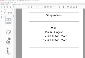
MTU Diesel Engine 12 V 4000 G23 G43 12 V 4000 G63 G83 16 V 4000 G23 G43 16 V 4000 G63 G83 Operation Instructions Manual M015710-01E PDF DOWNLOAD
$27.95
MTU Diesel Engine 12 V 4000 G23 G43, 12 V 4000 G63 G83, 16 V 4000 G23 G43, 16 V 4000 G63 G83 Operation Instructions Manual M015710-01E PDF DOWNLOAD
Instant PDF Download
Available immediately
Save to Your Device
Download & keep forever
Antivirus Scanned
100% virus-free
Trusted Worldwide
175,000+ customers
Description
MTU Diesel Engine 12 V 4000 G23 G43, 12 V 4000 G63 G83, 16 V 4000 G23 G43, 16 V 4000 G63 G83 Operation Instructions Manual M015710-01E PDF DOWNLOAD
FILE DETAILS:
MTU Diesel Engine 12 V 4000 G23 G43, 12 V 4000 G63 G83, 16 V 4000 G23 G43, 16 V 4000 G63 G83 Operation Instructions Manual M015710-01E PDF DOWNLOAD
Language : English
Pages : 180
Downloadable : Yes
File Type : PDF
IMAGES PREVIEW OF THE MANUAL:
Questions? Email us: [email protected]
https://vimeo.com/858923490?share=copy
DESCRIPTION:
MTU Diesel Engine 12 V 4000 G23 G43, 12 V 4000 G63 G83, 16 V 4000 G23 G43, 16 V 4000 G63 G83 Operation Instructions Manual M015710-01E PDF DOWNLOAD
SAFETY:
General Conditions
General Conditions
General:
- In addition to the instructions in this publication, the applicable country-specific legislation and other compulsory regulations regarding accident prevention must be observed.
- This engine is a state-of-the-art product and conforms with all applicable specifications and regulations.
- Nevertheless, persons and property may be at risk in the event of:
- Incorrect use.
- Operation, maintenance, and repair by unqualified personnel.
- Modifications or conversions.
- Non-compliance with the Safety Instructions.
Correct Use:
- The engine is intended exclusively for the application specified in the contract or defined at the time of delivery. Any other use is considered improper use.
- The manufacturer will accept no liability for any resultant damage. The responsibility is borne by the user alone.
- Correct use also includes observation of and compliance with the maintenance specifications.
Modifications or Conversions:
- Modifications made by the customer to the engine may affect safety.
- MTU will accept no liability or warranty claims for any damage caused by unauthorized modifications or conversions.
Spare Parts:
- Only genuine MTU spare parts must be used to replace components or assemblies.
- In the event of any damage caused by the use of other spare parts..
TABLE OF CONTENTS:
MTU Diesel Engine 12 V 4000 G23 G43, 12 V 4000 G63 G83, 16 V 4000 G23 G43, 16 V 4000 G63 G83 Operation Instructions Manual M015710-01E PDF DOWNLOAD
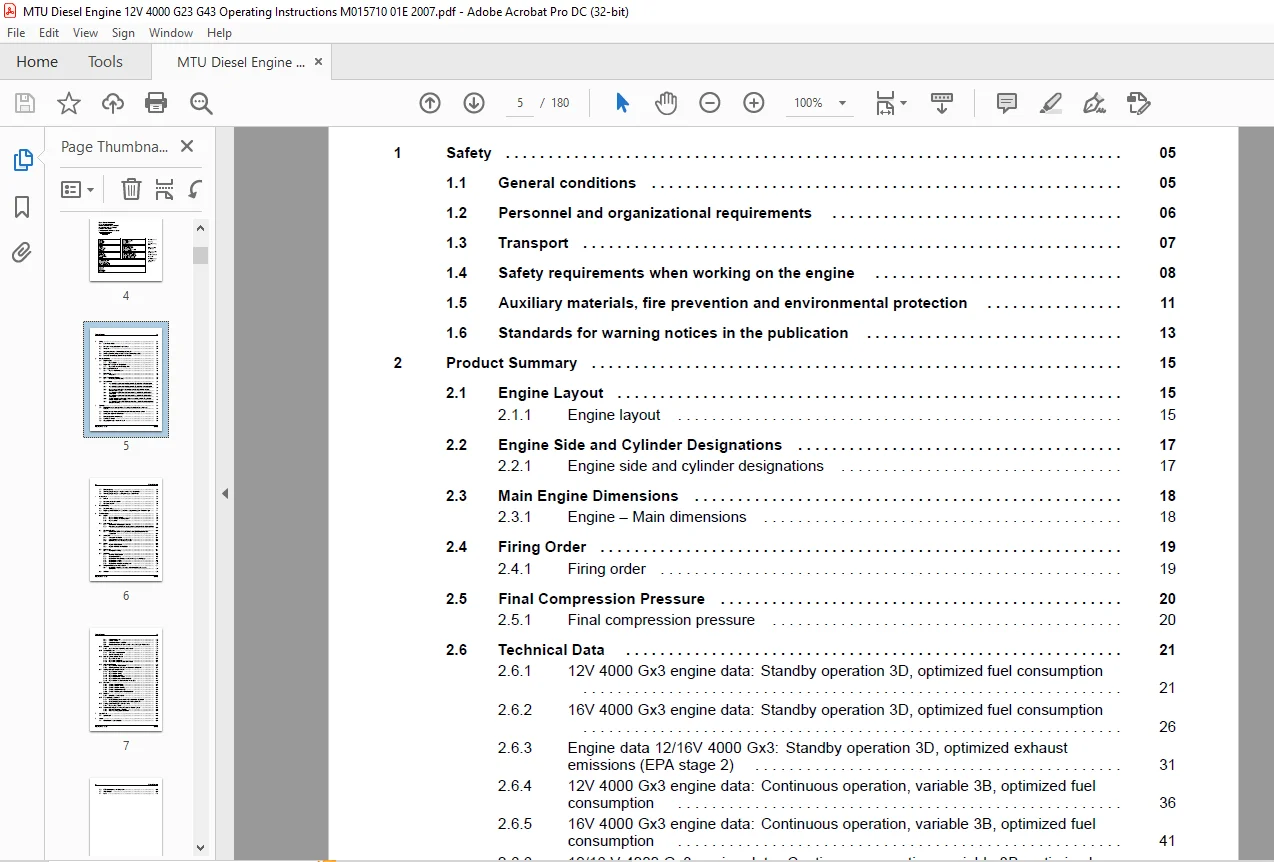
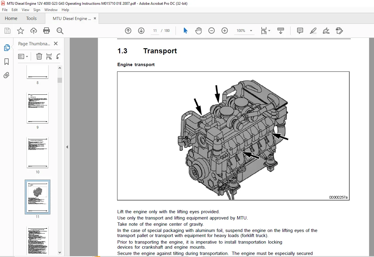
Title...................................................................................................................................  1
Commissioning Note......................................................................................................................  3
Table of Contents.......................................................................................................................  5
1 Safety................................................................................................................................  9
	1.1 General conditions..............................................................................................................  9
		General.........................................................................................................................  9
		Correct use.....................................................................................................................  9
		Modifications or Conversions....................................................................................................  9
		Spare parts.....................................................................................................................  9
	1.2 Personnel and organizational requirements ...................................................................................... 10
		Personnel ...................................................................................................................... 10
		Organization.................................................................................................................... 10
		Working clothes and protective equipment........................................................................................ 10
	1.3 Transport....................................................................................................................... 11
		Engine transport................................................................................................................ 11
		Setting the engine down after transport......................................................................................... 11
	1.4 Safety requirements when working on the engine.................................................................................. 12
		Safety precautions when putting the equipment into operation.................................................................... 12
		Safety requirements for operators............................................................................................... 12
		Engine operation................................................................................................................ 12
		Maintenance and repair.......................................................................................................... 12
		Welding work.................................................................................................................... 13
		Hydraulic installation and removal.............................................................................................. 13
		Working on electrical/electronic assemblies..................................................................................... 14
		Working with laser equipment.................................................................................................... 14
		Operation of electrical equipment............................................................................................... 14
	1.5 Auxiliary materials, fire prevention and environmental protection............................................................... 15
		Fire prevention................................................................................................................. 15
		Noise........................................................................................................................... 15
		Environmental protection........................................................................................................ 15
		Auxiliary materials............................................................................................................. 15
		Lead............................................................................................................................ 15
		Acids and alkaline solutions.................................................................................................... 15
		Paints.......................................................................................................................... 15
		Liquid nitrogen................................................................................................................. 15
		Compressed air.................................................................................................................. 16
		Used oil........................................................................................................................ 16
	1.6 Standards for warning notices in the publication................................................................................ 17
		Warning notices................................................................................................................. 17
2 Product Summary....................................................................................................................... 19
	2.1 Engine Layout................................................................................................................... 19
		2.1.1 Engine layout............................................................................................................. 19
			Illustration is also valid for 12V 4000 Gx3 engines......................................................................... 19
			Engine model designation.................................................................................................... 20
			Key to the engine model designations 12/16V 4000 Gx3........................................................................ 20
	2.2 Engine Side and Cylinder Designations........................................................................................... 21
		2.2.1 Engine side and cylinder designations..................................................................................... 21
	2.3 Main Engine Dimensions.......................................................................................................... 22
		2.3.1 Engine – Main dimensions.................................................................................................. 22
			Engine – Main dimensions.................................................................................................... 22
			Illustration is also valid for 12/16V engines............................................................................... 22
	2.4 Firing Order.................................................................................................................... 23
		2.4.1 Firing order.............................................................................................................. 23
			Firing order................................................................................................................ 23
	2.5 Final Compression Pressure...................................................................................................... 24
		2.5.1 Final compression pressure................................................................................................ 24
			Final compression pressure.................................................................................................. 24
	2.6 Technical Data.................................................................................................................. 25
		2.6.1 12V 4000 Gx3 engine data: Standby operation 3D, optimized fuel consumption ............................................... 25
			REFERENCE CONDITIONS........................................................................................................ 25
			POWER-RELATED DATA (performance refers to net brake power as per ISO 3046).................................................. 25
			GENERAL CONDITIONS (for maximum power)...................................................................................... 25
			MODEL RELATED DATA (basic design)........................................................................................... 26
			COMBUSTION AIR / EXHAUST GAS................................................................................................ 26
			COOLANT SYSTEM (HT circuit)................................................................................................. 27
			COOLING SYSTEM (LT circuit)................................................................................................. 27
			LUBE-OIL SYSTEM............................................................................................................. 27
			FUEL SYSTEM................................................................................................................. 28
			GENERAL OPERATING DATA...................................................................................................... 28
			CAPACITIES.................................................................................................................. 28
			WEIGHTS / MAIN DIMENSIONS................................................................................................... 28
			ACOUSTICS................................................................................................................... 29
		2.6.2 16V 4000 Gx3 engine data: Standby operation 3D, optimized fuel consumption ............................................... 30
			REFERENCE CONDITIONS........................................................................................................ 30
			POWER-RELATED DATA (performance refers to net brake power as per ISO 3046).................................................. 30
			GENERAL CONDITIONS (for maximum power)...................................................................................... 30
			MODEL RELATED DATA (basic design)........................................................................................... 31
			COMBUSTION AIR / EXHAUST GAS................................................................................................ 31
			COOLANT SYSTEM (HT circuit)................................................................................................. 32
			COOLING SYSTEM (LT circuit)................................................................................................. 32
			LUBE-OIL SYSTEM............................................................................................................. 32
			FUEL SYSTEM................................................................................................................. 33
			GENERAL OPERATING DATA...................................................................................................... 33
			CAPACITIES.................................................................................................................. 33
			WEIGHTS / MAIN DIMENSIONS................................................................................................... 33
			ACOUSTICS................................................................................................................... 34
		2.6.3 Engine data 12/16V 4000 Gx3: Standby operation 3D, optimized exhaust emissions (EPA stage 2).............................. 35
			REFERENCE CONDITIONS........................................................................................................ 35
			POWER-RELATED DATA (performance refers to net brake power as per ISO 3046).................................................. 35
			GENERAL CONDITIONS (for maximum power)...................................................................................... 35
			MODEL RELATED DATA (basic design)........................................................................................... 36
			COMBUSTION AIR / EXHAUST GAS................................................................................................ 36
			COOLANT SYSTEM (HT circuit)................................................................................................. 37
			COOLING SYSTEM (LT circuit)................................................................................................. 37
			LUBE-OIL SYSTEM............................................................................................................. 37
			FUEL SYSTEM................................................................................................................. 38
			GENERAL OPERATING DATA...................................................................................................... 38
			CAPACITIES.................................................................................................................. 38
			WEIGHTS / MAIN DIMENSIONS................................................................................................... 38
			ACOUSTICS................................................................................................................... 39
		2.6.4 12V 4000 Gx3 engine data: Continuous operation, variable 3B, optimized fuel consumption................................... 40
			REFERENCE CONDITIONS........................................................................................................ 40
			POWER-RELATED DATA (performance refers to net brake power as per ISO 3046).................................................. 40
			GENERAL CONDITIONS (for maximum power)...................................................................................... 40
			MODEL RELATED DATA (basic design)........................................................................................... 41
			COMBUSTION AIR / EXHAUST GAS................................................................................................ 41
			COOLANT SYSTEM (HT circuit)................................................................................................. 42
			COOLING SYSTEM (LT circuit)................................................................................................. 42
			LUBE-OIL SYSTEM............................................................................................................. 42
			FUEL SYSTEM................................................................................................................. 43
			GENERAL OPERATING DATA...................................................................................................... 43
			CAPACITIES.................................................................................................................. 43
			WEIGHTS / MAIN DIMENSIONS................................................................................................... 43
			ACOUSTICS................................................................................................................... 44
		2.6.5 16V 4000 Gx3 engine data: Continuous operation, variable 3B, optimized fuel consumption................................... 45
			REFERENCE CONDITIONS........................................................................................................ 45
			POWER-RELATED DATA (performance refers to net brake power as per ISO 3046).................................................. 45
			GENERAL CONDITIONS (for maximum power)...................................................................................... 45
			MODEL RELATED DATA (basic design)........................................................................................... 46
			COMBUSTION AIR / EXHAUST GAS................................................................................................ 46
			COOLANT SYSTEM (HT circuit)................................................................................................. 47
			COOLING SYSTEM (LT circuit)................................................................................................. 47
			LUBE-OIL SYSTEM............................................................................................................. 47
			FUEL SYSTEM................................................................................................................. 48
			GENERAL OPERATING DATA...................................................................................................... 48
			CAPACITIES.................................................................................................................. 48
			WEIGHTS / MAIN DIMENSIONS................................................................................................... 48
			ACOUSTICS................................................................................................................... 49
		2.6.6  12/16 V 4000 Gx3 engine data: Continuous operation, variable 3B, optimized exhaust emission (EPA stage 2)................ 50
			REFERENCE CONDITIONS........................................................................................................ 50
			POWER-RELATED DATA (performance refers to net brake power as per ISO 3046).................................................. 50
			GENERAL CONDITIONS (for maximum power)...................................................................................... 50
			MODEL RELATED DATA (basic design)........................................................................................... 51
			COMBUSTION AIR / EXHAUST GAS................................................................................................ 51
			COOLANT SYSTEM (HT circuit)................................................................................................. 52
			COOLING SYSTEM (LT circuit)................................................................................................. 52
			LUBE-OIL SYSTEM............................................................................................................. 52
			FUEL SYSTEM................................................................................................................. 53
			GENERAL OPERATING DATA...................................................................................................... 53
			CAPACITIES.................................................................................................................. 53
			WEIGHTS / MAIN DIMENSIONS................................................................................................... 53
			ACOUSTICS................................................................................................................... 54
		2.6.7 12V 4000 Gx3 engine data: Continuous operation, variable 3B , optimized exhaust emissions (TA-Luft)....................... 55
			REFERENCE CONDITIONS........................................................................................................ 55
			POWER-RELATED DATA (performance refers to net brake power as per 3046)...................................................... 55
			GENERAL CONDITIONS (for maximum power)...................................................................................... 55
			MODEL RELATED DATA (basic design)........................................................................................... 56
			COMBUSTION AIR / EXHAUST GAS................................................................................................ 56
			COOLANT SYSTEM (HT circuit)................................................................................................. 56
			COOLING SYSTEM (LT circuit)................................................................................................. 57
			LUBE-OIL SYSTEM............................................................................................................. 57
			FUEL SYSTEM................................................................................................................. 57
			GENERAL OPERATING DATA...................................................................................................... 57
			CAPACITIES.................................................................................................................. 58
			WEIGHTS / MAIN DIMENSIONS................................................................................................... 58
			ACOUSTICS................................................................................................................... 58
3 Operation............................................................................................................................. 59
	3.1 Putting the engine into operation after extended out-of-service-periods (>3 months)............................................. 59
		Putting the engine into operation after extended out-of-service-periods (>3 months)............................................. 59
	3.2 Putting the engine into operation after scheduled out-of-service-period......................................................... 60
	3.3 Starting the engine in manual mode.............................................................................................. 61
	3.4 Emergency start (override mode)................................................................................................. 62
	3.5 Operational checks.............................................................................................................. 63
	3.6 Stopping the engine in manual mode.............................................................................................. 64
	3.7 Emergency stop.................................................................................................................. 65
	3.8 After stopping the engine – engine remains ready for operation.................................................................. 66
	3.9 After stopping the engine – putting the engine out of service................................................................... 67
4 Maintenance........................................................................................................................... 69
	4.1 Preface......................................................................................................................... 69
		MTU maintenance concept......................................................................................................... 69
		Preventive maintenance instructions............................................................................................. 69
		Out-of-service periods.......................................................................................................... 69
		Application group............................................................................................................... 69
	4.2 Maintenance schedule matrix..................................................................................................... 70
		Maintenance schedule matrix for application group 3B, 0-10,000 operating hours.................................................. 70
		Maintenance schedule matrix for application group 3C, 0-6,000 operating hours................................................... 71
	4.3 Maintenance tasks............................................................................................................... 72
5 Troubleshooting....................................................................................................................... 75
	5.1 Troubleshooting................................................................................................................. 75
	5.2 Engine governor ADEC (ECU 7) for Series 4000 genset engines - Fault messages ................................................... 78
		The fault code numbers are generated by the Engine Control Unit and transmitted to the following display........................ 78
6 Task Description...................................................................................................................... 99
	6.1 Engine.......................................................................................................................... 99
		6.1.1 Engine – Barring manually................................................................................................. 99
		6.1.2 Engine – Barring with starting system.....................................................................................100
		6.1.3 Engine test run ..........................................................................................................101
	6.2 Cylinder Liner..................................................................................................................102
		6.2.1 Cylinder liner – Endoscopic examination...................................................................................102
		6.2.2 Instructions and comments on endoscopic and visual examination of cylinder liners.........................................104
			Terms used for endoscopic examination.......................................................................................104
			Use the terms listed below to describe the condition of the cylinder-liner surface in the endoscopic examination report.....104
			Evaluation of findings and further measures.................................................................................105
	6.3 Crankcase Breather..............................................................................................................106
		6.3.1 Crankcase breather – Oil separator replacement, diaphragm check and replacement...........................................106
	6.4 Valve Drive.....................................................................................................................108
		6.4.1 Valve gear – Lubrication..................................................................................................108
		6.4.2 Valve clearance – Check and adjustment....................................................................................109
		6.4.3 Cylinder head cover – Remove and install..................................................................................112
	6.5 Injector........................................................................................................................113
		6.5.1 Injector – Replacement....................................................................................................113
		6.5.2 Injector – Removal and Installation.......................................................................................114
	6.6 Fuel System.....................................................................................................................118
		6.6.1 Fuel system – Venting.....................................................................................................118
	6.7 Fuel Filter.....................................................................................................................119
		7 Special Tools.................................................................................................................163
			7.1 Special tools...........................................................................................................163
		6.7.1 Fuel filter – Replacement.................................................................................................119
		6.7.2 Fuel prefilter cleaning...................................................................................................120
		6.7.3 Fuel prefilter – differential pressure check and adjustment of gauge......................................................121
		6.7.4 Fuel prefilter – draining.................................................................................................122
		6.7.5 Fuel prefilter – flushing.................................................................................................124
		6.7.6 Fuel prefilter – filter element replacement...............................................................................126
	6.8 Charge-air Cooling, General, Left Side..........................................................................................128
		6.8.1 Intercooler – Checking condensate drains for coolant disscharge and obstructions..........................................128
	6.9 Air Filter......................................................................................................................129
		6.9.1 Air filter replacement....................................................................................................129
		6.9.2 Air filter – Check........................................................................................................130
		6.9.3 Air filter removal and installation.......................................................................................131
		6.9.4 Rubber sleeves between air intake elbow and turbocharger - Replacement....................................................132
	6.10 Air Intake.....................................................................................................................133
		6.10.1 Service indicator – Signal ring position check...........................................................................133
	6.11 Staring Equipment..............................................................................................................134
		6.11.1 Air starter – manual operation...........................................................................................134
		6.11.2 Starter – Condition check ...............................................................................................135
	6.12 Lube-oil System, Lube-oil Circuit..............................................................................................136
		6.12.1 Engine oil – Change......................................................................................................136
		6.12.2 Engine oil – Level check.................................................................................................138
		6.12.3 Engine oil – Sample extraction and analysis..............................................................................139
	6.13 Oil Filtration/Cooling.........................................................................................................140
		6.13.1 Engine oil filter – Replacement..........................................................................................140
		6.13.2 Centrifugal oil filter – Cleaning and filter-sleeve replacement..........................................................141
	6.14 Cooling Circuit, General, HT Circuit...........................................................................................143
		6.14.1 Engine coolant – Change..................................................................................................143
		6.14.2 Engine coolant – Filling ................................................................................................144
		6.14.3 Engine coolant – Draining................................................................................................146
		6.14.4 Engine coolant level – Check.............................................................................................147
		6.14.5 Engine coolant pump – Relief bore check .................................................................................148
		6.14.6 Engine coolant – Sample extraction and analysis..........................................................................149
	6.15 LT Circuit.....................................................................................................................150
		6.15.1 Charge-air coolant change................................................................................................150
		6.15.2 Charge-air coolant – Filling.............................................................................................151
		6.15.3 Charge-air coolant – Draining............................................................................................153
		6.15.4 Charge-air coolant level check...........................................................................................154
		6.15.5 Charge-air coolant pump – Relief bore check .............................................................................155
	6.16 Belt Drive.....................................................................................................................156
		6.16.1 Drive belt – Condition check.............................................................................................156
	6.17 Battery-charging Generator.....................................................................................................157
		6.17.1 Battery-charging generator drive – Drive belt tension adjustment.........................................................157
		6.17.2 Battery-charging generator drive – Drive belt replacement................................................................158
	6.18 Cabling, General for Engine / Gearbox / Plant..................................................................................159
		6.18.1 Engine wiring – Check....................................................................................................159
	6.19 Accessories for Engine Governor (Electronic) / Control System..................................................................160
		6.19.1 ECU and connectors – Cleaning............................................................................................160
		6.19.2 ECU – Checking plug-in connections.......................................................................................161
7 Special Tools.........................................................................................................................163
	7.1 Special tools...................................................................................................................163
8 Annex.................................................................................................................................171
8.1 Manufacturer’s documentation........................................................................................................171
	See Manufacturer’s documentation....................................................................................................171
	8.2 MTU contact person/service partner..............................................................................................172
	8.3 Abbreviations...................................................................................................................173
	8.4 Index...........................................................................................................................177
PLEASE NOTE:
- This is the same manual used by the dealers to diagnose and troubleshoot your vehicle
- You will be directed to the download page as soon as the purchase is completed. The whole payment and downloading process will take anywhere between 2-5 minutes
- Need any other service / repair / parts manual, please feel free to contact [email protected] . We still have 50,000 manuals unlisted
G.P