MTU Diesel Engine 12V2000Gx5 Gx5 TB 16V2000Gx5 Gx5 TB 18V2000Gx5 Gx5 TB Operating Instructions Manual MS15019-04E PDF DOWNLOAD
$25.95
MTU Diesel Engine 12V2000Gx5 Gx5 TB 16V2000Gx5 Gx5 TB 18V2000Gx5 Gx5 TB Operating Instructions Manual MS15019-04E PDF DOWNLOAD
Operating Instructions
Diesel engine
12V2000Gx5, Gx5 TB
16V2000Gx5, Gx5 TB
18V2000Gx5, Gx5 TB
Application group 3B
Description
MTU Diesel Engine 12V2000Gx5 Gx5 TB 16V2000Gx5 Gx5 TB 18V2000Gx5 Gx5 TB Operating Instructions Manual MS15019-04E PDF DOWNLOAD
FILE DETAILS:
MTU Diesel Engine 12V2000Gx5 Gx5 TB 16V2000Gx5 Gx5 TB 18V2000Gx5 Gx5 TB Operating Instructions Manual MS15019-04E PDF DOWNLOAD
Language : English
Pages : 170
Downloadable : Yes
File Type : PDF
IMAGES PREVIEW OF THE MANUAL:
TABLE OF CONTENTS:
MTU Diesel Engine 12V2000Gx5 Gx5 TB 16V2000Gx5 Gx5 TB 18V2000Gx5 Gx5 TB Operating Instructions Manual MS15019-04E PDF DOWNLOAD
Operating Instructions
Diesel engine
12V2000Gx5, Gx5 TB
16V2000Gx5, Gx5 TB
18V2000Gx5, Gx5 TB
Application group 3B
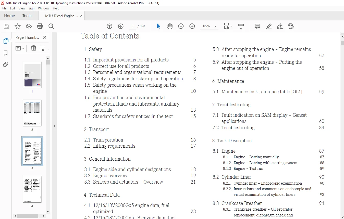
Operating Instructions..................................................................................  1
	Table of Contents...................................................................................  3
	1 Safety ...........................................................................................  5
		1.1 Important provisions for all products.......................................................  5
		1.2 Correct use for all products................................................................  6
		1.3 Personnel and organizational requirements...................................................  7
		1.4 Safety regulations for startup and operation................................................  8
		1.5 Safety precautions when working on the engine............................................... 10
		1.6 Fire prevention and environmental protection, fluids and lubricants, auxiliary materials.... 13
		1.7 Standards for safety notices in the text.................................................... 15
	2 Transport......................................................................................... 16
		2.1 Transportation.............................................................................. 16
		2.2 Lifting requirements........................................................................ 17
	3 General Information............................................................................... 18
		3.1 Engine side and cylinder designations....................................................... 18
		3.2 Engine overview............................................................................. 19
		3.3 Sensors and actuators – Overview............................................................ 21
	4 Technical Data.................................................................................... 23
		4.1 12/16/18V2000Gx5 engine data, fuel optimized................................................ 23
		4.2 12/16/18V2000Gx5-TB engine data, fuel optimized............................................. 28
		4.3 12V2000Gx5, engine data, emissions optimized................................................ 33
		4.4 16/18V2000Gx5 engine data, emissions optimized.............................................. 37
		4.5 12/16/18V2000Gx5-TB engine data, emissions optimized........................................ 43
		4.6 Firing order................................................................................ 48
		4.7 Engine – Main dimensions.................................................................... 49
	5 Operation......................................................................................... 50
		5.1 Putting the engine into operation after extended out-of-service periods (>3 months)......... 50
		5.2 Putting the engine into operation after scheduled out-of-service-period .................... 51
		5.3 Engine – Starting in manual mode (test run)................................................. 52
		5.4 Safety system – Override.................................................................... 53
		5.5 Operational monitoring...................................................................... 54
		5.6 Engine – Stopping in manual mode (test run)................................................. 55
		5.7 Engine – Emergency stop..................................................................... 56
		5.8 After stopping the engine – Engine remains ready for operation.............................. 57
		5.9 After stopping the engine – Putting the engine out of operation............................. 58
	6 Maintenance....................................................................................... 59
		6.1 Maintenance task reference table [QL1]...................................................... 59
	7 Troubleshooting................................................................................... 60
		7.1 Fault indication on SAM display – Genset applications....................................... 60
		7.2 Troubleshooting............................................................................. 84
	8 Task Description.................................................................................. 87
		8.1 Engine...................................................................................... 87
			8.1.1 Engine – Barring manually............................................................. 87
			8.1.2 Engine – Barring with starting system................................................. 88
			8.1.3 Engine – Test run..................................................................... 89
		8.2 Cylinder Liner.............................................................................. 90
			8.2.1 Cylinder liner – Endoscopic examination............................................... 90
			8.2.2 Instructions and comments on endoscopic and visual examination of cylinder liners..... 92
		8.3 Crankcase Breather.......................................................................... 94
			8.3.1 Crankcase breather – Oil separator replacement, diaphragm check and replacement....... 94
			8.3.2 Crankcase breather – Wire mesh cleaning............................................... 96
		8.4 Valve Drive................................................................................. 97
			8.4.1 Valve clearance – Check and adjustment................................................ 97
			8.4.2 Cylinder head cover – Removal and installation........................................100
		8.5 Injection Pump / HP Pump....................................................................101
			8.5.1 Injection pump – Replacement..........................................................101
			8.5.2 Injection pump – Removal and installation.............................................102
		8.6 Injection Valve / Injector..................................................................105
			8.6.1 Injector – Replacement................................................................105
			8.6.2 Injector – Removal and installation...................................................106
		8.7 Fuel System.................................................................................111
			8.7.1 Fuel injection line – Pressure pipe neck replacement..................................111
			8.7.2 Fuel – Draining.......................................................................114
			8.7.3 Fuel pressure relief valve – Removal and installation.................................116
			8.7.4 Fuel system – Venting.................................................................117
		8.8 Fuel Filter.................................................................................119
			8.8.1 Fuel filter – Replacement.............................................................119
			8.8.2 Fuel prefilter – Differential pressure gage check and adjustment of gage .............120
			8.8.3 Fuel prefilter – Draining.............................................................121
			8.8.4 Fuel prefilter – Flushing ............................................................123
			8.8.5 Fuel prefilter – Cleaning.............................................................125
			8.8.6 Fuel prefilter – Filter element replacement...........................................126
		8.9 Charge-Air Cooling General, Left-Hand Side..................................................128
			8.9.1 Intercooler – Checking condensate drain for coolant discharge and obstructions........128
		8.10 Air Filter.................................................................................129
			8.10.1 Air filter – Replacement.............................................................129
			8.10.2 Air filter – Removal and installation................................................130
		8.11 Air Intake.................................................................................131
			8.11.1 Service indicator – Signal ring position check.......................................131
		8.12 Starting Equipment.........................................................................132
			8.12.1 Air starter – Manual operation.......................................................132
		8.13 Lube Oil System, Lube Oil Circuit..........................................................133
			8.13.1 Engine oil – Level check.............................................................133
			8.13.2 Engine oil – Change..................................................................134
		8.14 Oil Filtration / Cooling...................................................................135
			8.14.1 Engine oil filter – Replacement......................................................135
		8.15 Coolant Circuit, General, High-Temperature Circuit.........................................136
			8.15.1 Engine coolant – Level check.........................................................136
			8.15.2 Engine coolant – Change..............................................................137
			8.15.3 Engine coolant – Draining............................................................138
			8.15.4 Engine coolant – Filling.............................................................139
			8.15.5 Coolant pump – Relief bore check.....................................................141
		8.16 Low-Temperature Circuit....................................................................142
			8.16.1 Charge-air coolant – Filling.........................................................142
			8.16.2 Charge-air coolant – Draining........................................................144
			8.16.3 Charge-air coolant – Change..........................................................145
			8.16.4 Charge-air coolant – Level check.....................................................146
		8.17 Battery-Charging Generator.................................................................147
			8.17.1 Battery-charging generator drive – Drive-belt check and adjustment...................147
			8.17.2 Battery-charging generator drive – Drive belt replacement............................149
		8.18 Fan Drive..................................................................................150
			8.18.1 Fan drive – Drive-belt check and adjustment..........................................150
			8.18.2 Fan drive – Drive belt replacement...................................................153
		8.19 Wiring (General) for Engine/Gearbox/Unit...................................................154
			8.19.1 Engine cabling – Check...............................................................154
		8.20 Accessories for (Electronic) Engine Governor / Control System .............................155
			8.20.1 Engine governor and connector – Cleaning.............................................155
			8.20.2 Engine governor plug connections – Check.............................................156
			8.20.3 Engine governor ECU 7 – Removal and installation.....................................157
	9 Appendix A........................................................................................158
		9.1 Abbreviations ..............................................................................158
		9.2 MTU Contact/Service Partners................................................................161
	10 Appendix B.......................................................................................162
		10.1 Special Tools..............................................................................162
		10.2 Index......................................................................................169
Customer Support: [email protected]
https://vimeo.com/858569010?share=copy
DESCRIPTION:
MTU Diesel Engine 12V2000Gx5 Gx5 TB 16V2000Gx5 Gx5 TB 18V2000Gx5 Gx5 TB Operating Instructions Manual MS15019-04E PDF DOWNLOAD
- Incorrect use
- Operation, maintenance, and repair by unqualified personnel
- Modifications or conversions
- Noncompliance with the safety instructions and warning notices
- The relevant emission labels must be affixed to the spare part.
- Do not transfer the emission labels from the replaced part to the spare part.
- Remove the emission labels from the replaced part and destroy them.
PLEASE NOTE:
- This is the same manual used by the dealers to diagnose and troubleshoot your vehicle
- You will be directed to the download page as soon as the purchase is completed. The whole payment and downloading process will take anywhere between 2-5 minutes
- Need any other service / repair / parts manual, please feel free to contact [email protected] . We still have 50,000 manuals unlisted
G.P