Mustang 170Z Compact Excavator Parts Manual 50940096 – PDF DOWNLOAD
Original price was: $89.95.$28.95Current price is: $28.95.
Mustang 170Z Compact Excavator Parts Manual 50940096 – PDF DOWNLOAD
Description
Mustang 170Z Compact Excavator Parts Manual 50940096 – PDF DOWNLOAD
FILE DETAILS:
Mustang 170Z Compact Excavator Parts Manual 50940096 – PDF DOWNLOAD
Language : English
Pages : 216
Downloadable : Yes
File Type : PDF
Size: 8.59 MB
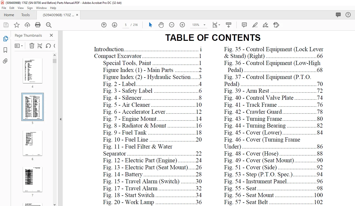
TABLE OF CONTENTS:
Mustang 170Z Compact Excavator Parts Manual 50940096 – PDF DOWNLOAD
Introduction i
Compact Excavator 1
Special Tools, Paint 1
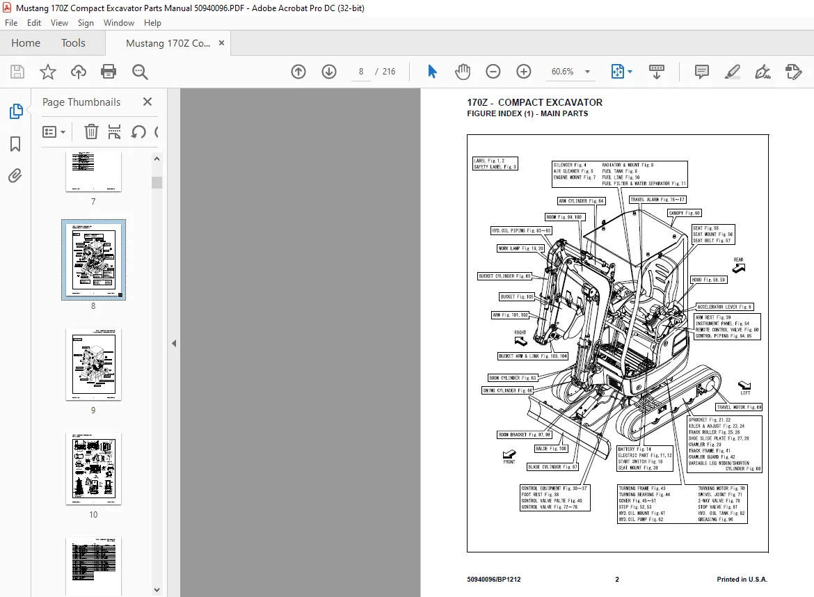
Figure Index (1) – Main Parts 2
Figure Index (2) – Hydraulic Section 3
Fig 2 – Label 4
Fig 3 – Safety Label 6
Fig 4 – Silencer 8
Fig 5 – Air Cleaner 10
Fig 6 – Accelerator Lever 12
Fig 7 – Engine Mount 14
Fig 8 – Radiator & Mount 16
Fig 9 – Fuel Tank 18
Fig 10 – Fuel Line 20
Fig 11 – Fuel Filter & Water
Separator 22
Fig 12 – Electric Part (Engine) 24
Fig 13 – Electric Part (Seat Mount) 26
Fig 14 – Battery 28
Fig 15 – Travel Alarm (Switch) 30
Fig 17 – Travel Alarm 32
Fig 18 – Start Switch 34
Fig 20 – Work Lamp 36
Fig 21 – Sprocket (Rubber Crawler) 38
Fig 22 – Sprocket (Iron Crawler) 40
Fig 23 – Idler & Adjust (Rubber
Crawler) 42
Fig 24 – Idler & Adjust (Iron
Crawler) 44
Fig 25 – Track Roller (Rubber
Crawler) 46
Fig 26 – Track Roller (Iron Crawler) 48
Fig 27 – Shoe Side Plate (Rubber
Crawler) 50
Fig 28 – Shoe Side Plate (Iron
Crawler) 52
Fig 29 – Crawler 54
Fig 30 – Control Equipment (Travel
Lever) 56
Fig 31 – Control Equipment (Blade
Lever) 58
Fig 32 – Control Equipment (Variable
Leg Lever) 60
Fig 33 – Control Equipment (Swing
Pedal) 62
Fig 34 – Control Equipment (Lock Lever
& Stand) (Left) 64
Fig 35 – Control Equipment (Lock Lever
& Stand) (Right) 66
Fig 36 – Control Equipment (Low-High
Pedal) 68
Fig 37 – Control Equipment (P T O
Pedal) 70
Fig 39 – Arm Rest 72
Fig 40 – Control Valve Plate 74
Fig 41 – Track Frame 76
Fig 42 – Crawler Guard 78
Fig 43 – Turning Frame 80
Fig 44 – Turning Bearing 82
Fig 45 – Cover (Lower) 84
Fig 46 – Cover (Turning Frame
Under) 86
Fig 48 – Cover (Hose) 88
Fig 49 – Cover (Seat Mount) 90
Fig 51 – Cover (Side) 92
Fig 53 – Step (P T O Spec ) 94
Fig 54 – Instrument Panel 96
Fig 55 – Seat 98
Fig 56 – Seat Mount 100
Fig 57 – Seat Belt 102
Fig 59 – Hood 104
Fig 60 – Canopy 106
Fig 61 – Pump Mount 108
Fig 62 – Hyd Oil Pump 110
Fig 63 – Boom Cylinder 112
Fig 64 – Arm Cylinder 114
Fig 65 – Bucket Cylinder 116
Fig 66 – Swing Cylinder 118
Fig 67 – Blade Cylinder 120
Fig 68 – Variable Leg Widen/Shorten
Cylinder 122
Fig 69 – Travel Motor 124
Fig 70 – Turning Motor 126
Fig 71 – Swivel Joint 128
Fig 72 – Control Valve (1/7) 130
Fig 73 – Control Valve (2/7) 132
Fig 74 – Control Valve (3/7) 134
Fig 75 – Control Valve (4/7) 136
Fig 76 – Control Valve (5/7) 138
Fig 77 – Control Valve (6/7) 140
Fig 78 – Control Valve (7/7) 142
Fig 79 – 2-Way Valve 144
Fig 80 – Remote Control Valve 146
Fig 81 – Stop Valve 148
50940096/BP1212 II Printed in U S A
TABLE OF CONTENTS
Fig 82 – Hyd Oil Tank 150
Fig 83 – Hyd Oil Piping (Pump) 152
Fig 84 – Hyd Oil Piping (Lower) 154
Fig 85 – Hyd Oil Piping (Swivel
Joint) 156
Fig 86 – Hyd Oil Piping (IMP) 158
Fig 87 – Hyd Oil Piping (Turning
Motor) 160
Fig 88 – Hyd Oil Piping (Swing
Cylinder) 162
Fig 89 – Hyd Oil Piping
(Reservoir) 164
Fig 90 – Hyd Oil Piping (Return) 166
Fig 91 – Hyd Oil Piping (Control
Valve) 168
Fig 93 – Hyd Oil Piping (P T O ) 170
Fig 94 – Control Piping (1) 172
Fig 95 – Control Piping (2) 174
Fig 96 – Greasing 176
Fig 98 – Boom Bracket 178
Fig 100 – Boom 180
Fig 102 – Arm 182
Fig 104 – Bucket Arm & Link 184
Fig 106 – Blade 186
Hydraulic Quick-Connect Couplers 188
Index 191
Numerical Index 193
Torque Charts Inside Back Cover
DESCRIPTION:
Mustang 170Z Compact Excavator Parts Manual 50940096 – PDF DOWNLOAD
INTRODUCTION:
General:
• MANITOU AMERICAS, INC. reserves the right to make changes or improvements in the design or construction of any part of the machine without incurring the obligation to install such changes on any previously delivered machines.
• This parts manual should not be used as a technical data reference; it uses simplified illustrations and does not detail servicing procedures.
• Internal engine components not shown in this manual are contained in a separate engine parts manual. The engine parts manual is contained in the documentation packet shipped with the machine, and is also available separately. Contact your dealer with any documentation requests.
Parts Ordering Information:
IMAGES PREVIEW OF THE MANUAL:
Contact us: [email protected]
https://vimeo.com/805011156
PLEASE NOTE:
- This is the SAME manual used by the dealers to troubleshoot any faults in your vehicle. This can be yours in 2 minutes after the payment is made.
- Contact us at [email protected] should you have any queries before your purchase or that you need any other service / repair / parts operators manual.
S.V