Mustang 634 Telehandler Service Parts Manual 908484 – PDF DOWNLOAD
Original price was: $86.95.$25.95Current price is: $25.95.
Mustang 634 Telehandler Service Parts Manual 908484 – PDF DOWNLOAD
S/N 71101 and Before
Description
Mustang 634 Telehandler Service Parts Manual 908484 – PDF DOWNLOAD
FILE DETAILS:
Mustang 634 Telehandler Service Parts Manual 908484 – PDF DOWNLOAD
Language : English
Pages : 150
Downloadable : Yes
File Type : PDF
Size: 3.41 MB
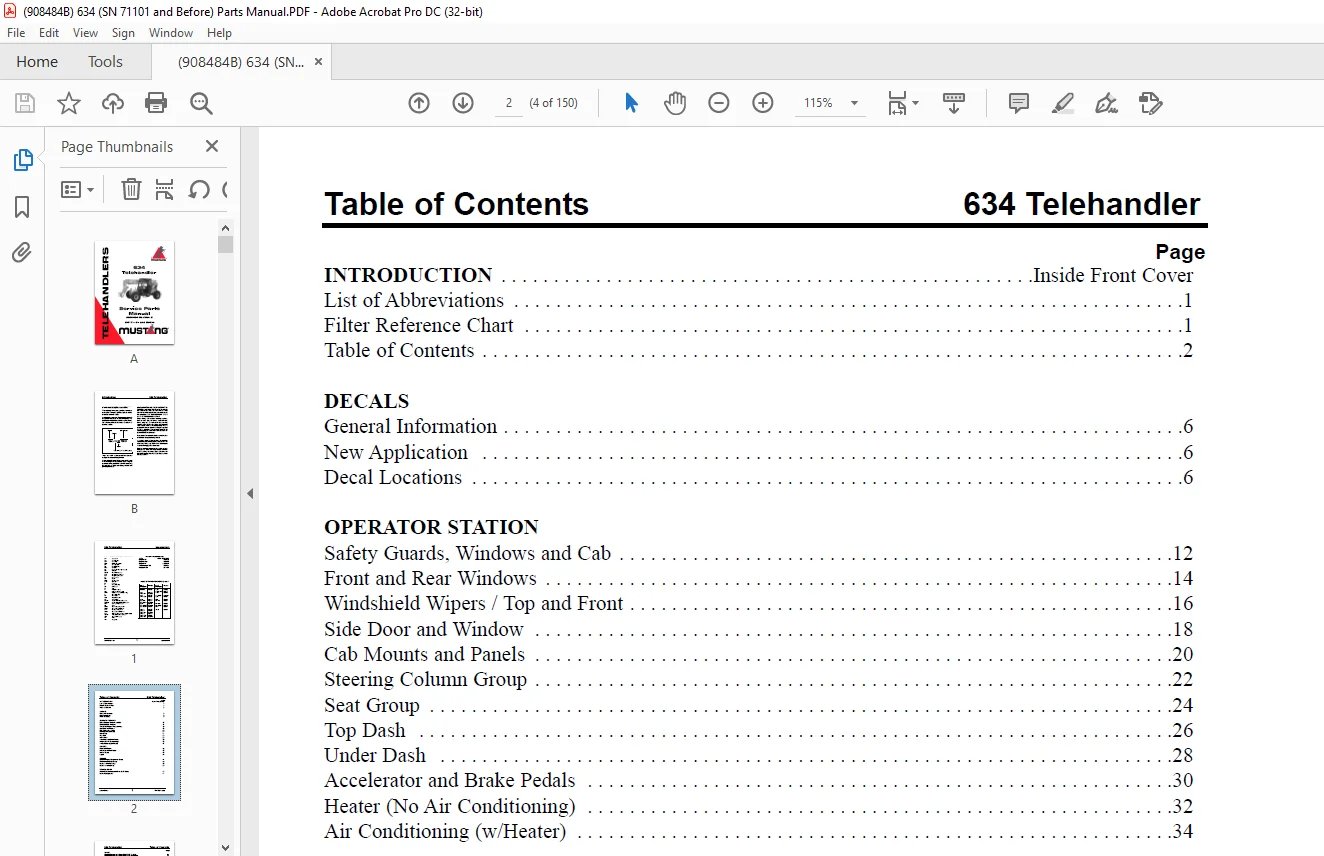
TABLE OF CONTENTS:
Mustang 634 Telehandler Service Parts Manual 908484 – PDF DOWNLOAD
INTRODUCTION Inside Front Cover
List of Abbreviations 1
Filter Reference Chart 1
Table of Contents 2
DECALS
General Information 6
New Application 6
Decal Locations 6
OPERATOR STATION
Safety Guards, Windows and Cab 12
Front and Rear Windows 14
Windshield Wipers / Top and Front 16
Side Door and Window 18
Cab Mounts and Panels 20
Steering Column Group 22
Seat Group 24
Top Dash 26
Under Dash 28
Accelerator and Brake Pedals 30
Heater (No Air Conditioning) 32
Air Conditioning (w/Heater) 34
CHASSIS
Frame and Covers 36
Hydraulic and Fuel Tanks 38
Battery Group 40
Lights 42
ENGINE
External Engine Components Group 44
Radiator and Cooler Group 46
Engine Air Intake Group 48
Engine Exhaust Group 50
TRANSMISSION
External Transmission and Drive Shaft Group 52
Internal Components 54
Table of Contents 634 Telehandler
PRINTED IN U S A 3 908484/BP0615
Page
AXLES
External Components Group (S/N 70017 – 71101) 56
External Components Group (S/N 70016 and before) 58
Outer End Group (S/N 70017 – 71101) 60
Outer End Group – Part I (S/N 70016 and before) 62
Outer End Group – Part II (S/N 70016 and before) 64
Differential Housing Group (S/N 70017 – 71101) 66
Differential Group (S/N 70017 – 71101) 68
Differential Housing Group – Part I (S/N 70016 and before) 70
Differential Housing Group – Part II (S/N 70016 and before) 72
Differential Housing Group – Part III (S/N 70016 and before) 74
Brake Group (S/N 70017 – 71101) 76
Brake Group (S/N 70016 and before) 78
BOOM
Outer Boom Section 80
Intermediate Boom Section 82
Inner Boom Section 84
Quickattach 86
HYDRAULIC SYSTEMS
Hydraulic Pump and Flow Divider 88
Steer Motor and Steer Select Valve 90
Main Valve Group 92
Joystick Controller Group 94
Frame Level Group 96
Lift Cylinder Group 98
Tilt / Slave Cylinder Group 100
Boom Extend Cylinder Group 102
Auxilary Hydraulics Group 104
HYDRAULIC COMPONENTS
Hydraulic Pump 106
Flow Divider Breakdown 107
Main Valve Breakdown 108
Auxilary Hydraulics Work Section Breakdown 108
Steer Cylinders Breakdown 110
Steer Valve Breakdown 111
Steer Motor Breakdown 112
Brake Valve Breakdown 113
Joystick Controller Breakdown 114
Auxilary Hydraulic Joystick Breakdown 116
(Continued on next page)
634 Telehandler Table of Contents
908484/BP0615 4 PRINTED IN U S A
Page
HYDRAULIC COMPONENTS (CONTINUED)
Frame Level Cylinder Breakdown 118
Lift Cylinder Breakdown 120
Slave Cylinder Breakdown 122
Tilt Cylinder Breakdown 124
Boom Extend Cylinder Breakdown 126
Fork Shift Carriage Cylinder Breakdown 128
Rotate Carriage Cylinder Breakdown 129
ATTACHMENTS
Standard Carriage Attachment Group 130
Shift Fork Carriage Attachment Group 132
Rotate Carriage Attachment Group 134
Boom Attachment Group 136
Bucket Attachment Group 138
NUMERICAL INDEX
Numerical Index List 140
DESCRIPTION:
Mustang 634 Telehandler Service Parts Manual 908484 – PDF DOWNLOAD
S/N 71101 and Before
Introduction:
The table of contents pages show the page location of various component groups on the machine.
- When ordering service parts, specify the correct part number, full description, quantity required, and the unit model and serial number.
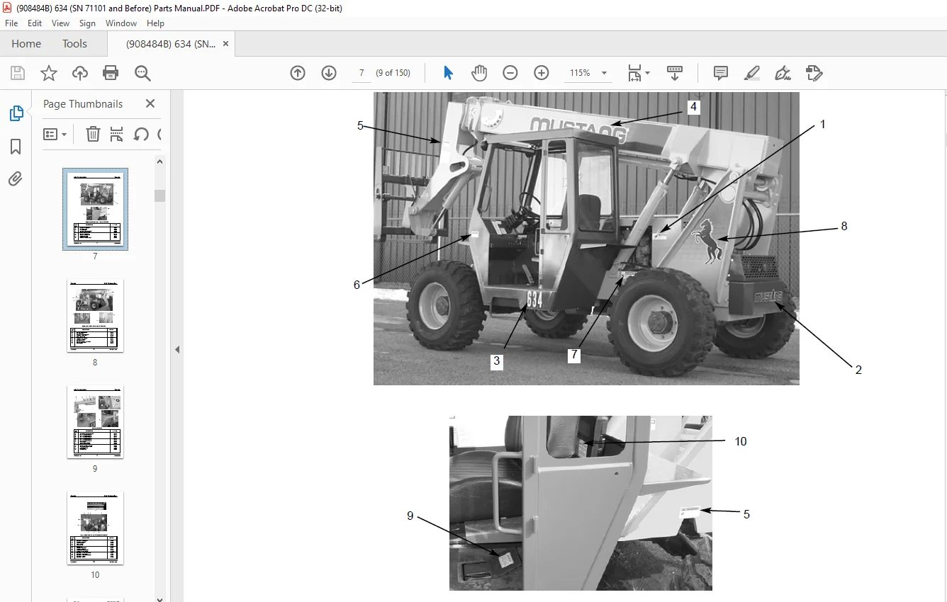
- Model and serial numbers for this unit are stamped on a plate located inside the operator’s station. The serial number is also stamped on the top front frame. The following reference shows the breakdown of the serial number:
- “Right” and “Left” are determined from a position sitting on the seat and facing forward. Mustang Manufacturing Company reserves the right to make changes or improvements in the design or construction of any part of the unit without incurring the obligation to install such changes on any unit previously delivered.
- Grease fittings and common attaching hardware, such as cotter pins, set screws, woodruff keys, screws, nuts, etc., are included in the parts list, indented below the part it is (they are) associated with, but may NOT be illustrated, except where a particular routing or special fastening arrangement MUST be maintained. The hardware listed is for mounting purposes and is NOT included when the part is ordered for replacement.
- Part numbers for standard hardware are listed indented under the component being fastened.
- A complete listing of part numbers for attaching washers/nuts used on this machine is included in the table on the facing page. Refer to the abbreviations list on the facing page for descriptions.
- Standard attaching hardware torque values are provided on the inside back cover. Unless otherwise specified, all cap screws are Grade 5, cadmium or zinc plated; hexagon nuts for Grade 5 cap screws or bolts are Grade A.
IMAGES PREVIEW OF THE MANUAL:
Need help? Contact: [email protected]
https://vimeo.com/804800017
PLEASE NOTE:
- This is the same manual used by the DEALERSHIPS to SERVICE your vehicle.
- The manual can be all yours – Once payment is complete, you will be taken to the download page from where you can download the manual. All in 2-5 minutes time!!
- Need any other service / repair / parts manual, please feel free to contact us at heydownloadss @gmail.com . We may surprise you with a nice offer
S.V