Mustang 642 844 1055 Telehandler Parts Manual 50960053 – PDF DOWNLOAD
Original price was: $86.95.$28.95Current price is: $28.95.
Mustang 642 844 1055 Telehandler Parts Manual 50960053 – PDF DOWNLOAD
642; Beginning with SN 80301
844; Beginning with SN 90301
1055; Beginning with SN 10301
Description
Mustang 642 844 1055 Telehandler Parts Manual 50960053 – PDF DOWNLOAD
FILE DETAILS:
Mustang 642 844 1055 Telehandler Parts Manual 50960053 – PDF DOWNLOAD
Language : English
Pages : 326
Downloadable : Yes
File Type : PDF
Size: 7.67 MB
TABLE OF CONTENTS:
Mustang 642 844 1055 Telehandler Parts Manual 50960053 – PDF DOWNLOAD
Introduction
Table of Contents 1
Filters, Belts, Analysis Kits 6
Cab
Standard Cab 8
Front and Rear Window – Enclosed Cab 10
Wipers – Front and Top – Enclosed Cab 12
Top and Left Window – Enclosed Cab 14
Door – Enclosed Cab 16
Instrument Panel and Switches 18
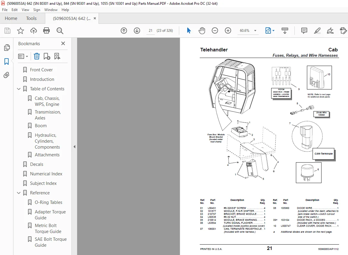
Fuses, Relays, and Wire Harnesses 20
Front and Rear Lights 22
Heater – (Option) – (No A/C) 24
A/C – Heater (A/C – Option) 25
A/C Circuit (Option) 26
Heater Circuit (A/C Equipped – Option) 28
A/C Condenser – (A/C Equipped – Option) 30
Steering Column Components 32
Seat 34
Tri-Function Cab Components – Option 36
Brake and Accelerator Pedals 38
Brake Valve 40
Cab Mounts 42
Chassis, Covers and Tanks
Hoods and Covers – Front-Half 44
Hoods and Covers – Rear-Half 46
Fuel Tank and Battery 48
Hydraulic Tank 50
Outriggers – Option 52
Outrigger Valve – Option 54
WPS (Work Platform System)
Chassis Components 56
Components (Three-Section Boom) 58
Components (Four-Section Boom) 59
Radio Remote Control – Transmitter and Receiver 60
Engine
External Components 62
A/C Compressor and Fan Belt – (Option) 64
Air Intake 66
Exhaust 68
Radiator and Coolers – Part 1 of 2 70
Radiator and Coolers – Part 2 of 2 72
Page
50960053/AP1112 2 PRINTED IN U S A
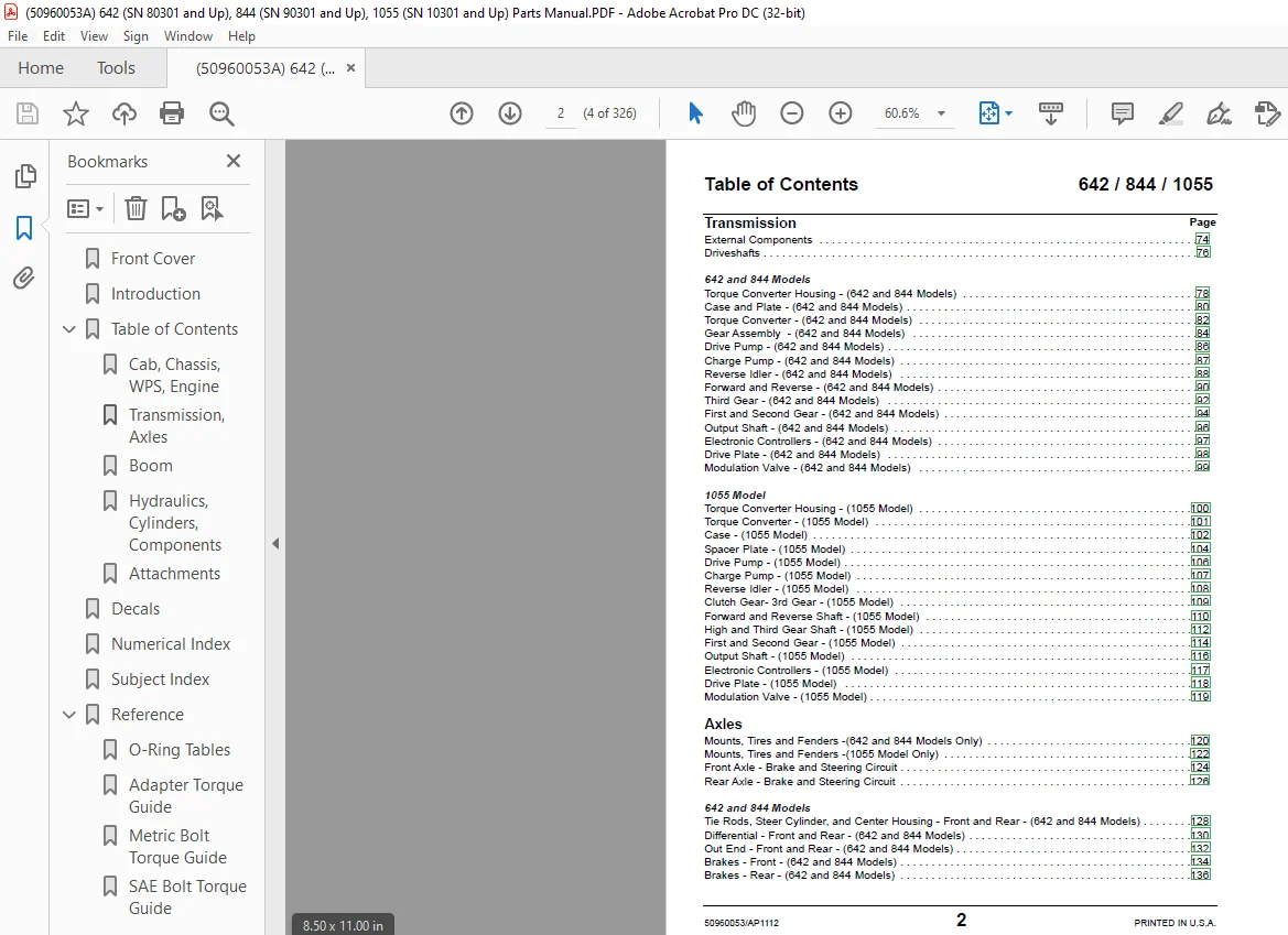
Transmission
External Components 74
Driveshafts 76
642 and 844 Models
Torque Converter Housing – (642 and 844 Models) 78
Case and Plate – (642 and 844 Models) 80
Torque Converter – (642 and 844 Models) 82
Gear Assembly – (642 and 844 Models) 84
Drive Pump – (642 and 844 Models) 86
Charge Pump – (642 and 844 Models) 87
Reverse Idler – (642 and 844 Models) 88
Forward and Reverse – (642 and 844 Models) 90
Third Gear – (642 and 844 Models) 92
First and Second Gear – (642 and 844 Models) 94
Output Shaft – (642 and 844 Models) 96
Electronic Controllers – (642 and 844 Models) 97
Drive Plate – (642 and 844 Models) 98
Modulation Valve – (642 and 844 Models) 99
1055 Model
Torque Converter Housing – (1055 Model) 100
Torque Converter – (1055 Model) 101
Case – (1055 Model) 102
Spacer Plate – (1055 Model) 104
Drive Pump – (1055 Model) 106
Charge Pump – (1055 Model) 107
Reverse Idler – (1055 Model) 108
Clutch Gear- 3rd Gear – (1055 Model) 109
Forward and Reverse Shaft – (1055 Model) 110
High and Third Gear Shaft – (1055 Model) 112
First and Second Gear – (1055 Model) 114
Output Shaft – (1055 Model) 116
Electronic Controllers – (1055 Model) 117
Drive Plate – (1055 Model) 118
Modulation Valve – (1055 Model) 119
Axles
Mounts, Tires and Fenders -(642 and 844 Models Only) 120
Mounts, Tires and Fenders -(1055 Model Only) 122
Front Axle – Brake and Steering Circuit 124
Rear Axle – Brake and Steering Circuit 126
642 and 844 Models
Tie Rods, Steer Cylinder, and Center Housing – Front and Rear – (642 and 844 Models) 128
Differential – Front and Rear – (642 and 844 Models) 130
Out End – Front and Rear – (642 and 844 Models) 132
Brakes – Front – (642 and 844 Models) 134
Brakes – Rear – (642 and 844 Models) 136
Table of Contents 642 / 844 / 1055
Page
PRINTED IN U S A 3 50960053/AP1112
Telehandler Table of Contents
(Axles Continued )
1055 Model
Front and Rear Axle – Steer Cylinder, Central Housing and Trunion – (1055 Model) 138
Front Axle – Differential – (1055 Model) 140
Front Axle – Hub Reduction – (1055 Model) 142
Rear Axle – Differential – (1055 Model) 144
Rear Axle – Hub Reduction – (1055 Model) 146
Front Axle – Brakes – (1055 Model) 148
Rear Axle – Brakes – (1055 Model) 149
Boom
3-Section Boom
3-Section Boom – Outer – Front 150
3-Section Boom – Outer – Rear 152
3-Section Boom – Outer Side Cover 153
3-Section Boom – Intermediate – Front 154
3-Section Boom – Intermediate – Rear 155
3-Section Boom – Intermediate Hose Tray 156
3-Section Boom – Chain and Rollers – Front 158
3-Section Boom – Chain and Rollers – Rear 160
3-Section Boom – Inner – Rear 162
4-Section Boom
4-Section Boom – Outer – Front 164
4-Section Boom – Outer – Rear 166
4-Section Boom – Outer Side Cover 167
4-Section Boom – 1st Intermediate – Front 168
4-Section Boom – 1st Intermediate – Rear 170
4-Section Boom – 1st Intermediate – Hose Tray 171
4-Section Boom – 2nd Intermediate – Front 172
4-Section Boom – 2nd Intermediate – Rear 174
4-Section Boom – Inner – Rear 176
3- and 4-Section Boom
3- and 4-Section Boom – Inner – Front 178
Dynattach® Assembly 180
Boom Hydraulics
3-Section Boom – Boom Extend/Retract 182
4-Section Boom – Boom Extend/Retract 184
3-Section Boom – Tilt 186
4-Section Boom – Tilt 188
3-Section Boom – Auxiliary Hydraulics Circuit 190
4-Section Boom – Auxiliary Hydraulics Circuit 192
Slave Cylinder Circuit 194
Boom Lift Circuit 196
Page
50960053/AP1112 4 PRINTED IN U S A
Table of Contents 642 / 844 / 1055
Chassis Hydraulics
Frame Level 198
Frame Stabilizing 200
Hydraulics
Hydraulic Pump and Flow Divider Circuit 202
Steering 204
Main Valve 206
Main Valve – Dual Controllers 208
Main Valve – Tri-Function Controller 210
Main Valve – Tri-Function Controller – with Auxiliary Hydraulics 212
Main Valve – Tri-Function Controller – with PWP 214
Main Valve – Tri-Function Controller – with PWP and Auxiliary Hydraulics 216
Main Valve – Radio Remote Control Option 218
Dual Controllers 220
Dual Controllers – with Auxiliary Hydraulics 222
Dual Controllers – with PWP 224
Dual Controllers – with PWP and Auxiliary Hydraulics 226
Dual Controllers – Radio Remote 228
Dual Controllers – Radio Remote – with Auxiliary Hydraulics 230
Tri-Function Controller 232
Tri-Function Controller – with PWP 234
Tri-Function Controller – Radio Remote 236
Hydraulic Cylinders
Frame Level 238
Frame Stabilizing 239
Boom Lift 240
Boom Extend – 3-Section Boom 242
Boom Extend – 4-Section Boom 244
Slave 246
Tilt 247
Outrigger 248
Grapple Cylinder 249
Rotating-Carriage 250
Swing-Carriage 251
Fork-Shift 252
Hydraulic Components
Hydraulic Pump 254
Brake Cylinder with Booster 255
Steer Motor 256
Steer Select Valve 257
Priority Valve 258
Flow Divider Valve 259
Pilot Apply Valve – Tri-Function Controller 260
Page
PRINTED IN U S A 5 50960053/AP1112
Telehandler Table of Contents
Page
PWP/WPS Valve 261
Frame Stabilizing Valve 262
Radio Remote Manifold 263
Main Valve 264
Main Valve – Auxiliary Hydraulics Work Section 266
Outrigger Valve 268
Controller – Tilt/Frame Level 270
Controller – Boom Lift/Extend 272
Controller – Auxiliary Hydraulics (Standard) – Frame Level (Tri-Function) 274
Controller – Tri-Function 276
Attachments
Carriage Forks 278
Standard Carriage 280
Fork-Shift Carriage 282
Rotating Carriage 284
90º Swing Carriage 286
180º Swing Carriage 288
Log/Pipe Carriage 290
Truss Boom and Winch 292
Bucket 294
Decals
Decal Application and Paint 295
Decal Locations 296
Index
Numerical Index 300
Subject Index 312
Reference
O-Ring Tables 320
Adapter (Fittings) Torque Guide 321
Metric Bolt Torque Guide 322
SAE Bolt Torque Guide 323
DESCRIPTION:
Mustang 642 844 1055 Telehandler Parts Manual 50960053 – PDF DOWNLOAD
642; Beginning with SN 80301
844; Beginning with SN 90301
1055; Beginning with SN 10301
Introduction:
When ordering service parts, specify the part number, full description, quantity required, and
the unit model and serial number.
- Model and serial numbers for this unit are stamped on a plate located inside the operator’s station. The serial number is also stamped on the top front of the frame. The above reference shows the breakdown of the serial number.
- ‘Right‘ and “left” are determined from a position standing behind the unit and facing the direction of forward travel.
- Mustang Manufacturing Company reserves the right to make changes or improvements in the design or construction of any part of the unit with- out incurring the obligation to install such changes on any unit previously delivered.
- The following icons appear on various pages throughout the manual; they are used to inform, as well as direct you to more information.
IMAGES PREVIEW OF THE MANUAL:
Need help? Contact: [email protected]
https://vimeo.com/804805960
PLEASE NOTE:
- This is the same manual used by the DEALERSHIPS to SERVICE your vehicle.
- The manual can be all yours – Once payment is complete, you will be taken to the download page from where you can download the manual. All in 2-5 minutes time!!
- Need any other service / repair / parts manual, please feel free to contact us at heydownloadss @gmail.com . We may surprise you with a nice offer
S.V