Mustang Manitou 106 MLA-1 Articulated Loader Parts Manual 50940351 – PDF DOWNLOAD
Original price was: $86.95.$24.95Current price is: $24.95.
Mustang Manitou 106 MLA-1 Articulated Loader Parts Manual 50940351 – PDF DOWNLOAD
(SN 13000 and Up)
Description
Mustang Manitou 106 MLA-1 Articulated Loader Parts Manual 50940351 – PDF DOWNLOAD
FILE DETAILS:
Mustang Manitou 106 MLA-1 Articulated Loader Parts Manual 50940351 – PDF DOWNLOAD
Language : English
Pages : 124
Downloadable : Yes
File Type : PDF
Size: 8.26 MB
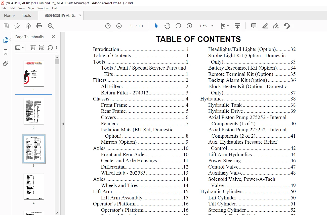
TABLE OF CONTENTS:
Mustang Manitou 106 MLA-1 Articulated Loader Parts Manual 50940351 – PDF DOWNLOAD
Introduction i
Table of Contents I
Tools 1
Tools / Paint / Special Service Parts and
Kits 1
Filters 2
All Filters 2
Return Filter – 274912 3
Chassis 4
Front Frame 4
Rear Frame 5
Covers 6
Fenders 7
Isolation Mats (EU-Std, Domestic-
Option) 8
Mirrors (Option) 9
Axles 10
Front and Rear Axles 10
Center and Axle Housings 11
Differential 12
Wheel Hub – 202585 13
Axles 14
Wheels and Tires 14
Lift Arm 15
Lift Arm Assembly 15
Operator’s Platform 16
Operator’s Platform 16
Seat and Seatbelt 18
Steering Column – Standard 19
Steering Column – Deluxe (EU
Only) 20
ROPS/FOPS 22
ROPS – Two-Post and Four-Post 22
Side Gates – Four-Post ROPS 23
Controls 24
Service Brake, Parking Brake,
Throttle 24
Inching 25
Electrical 26
Main Machine 26
Battery Cables (w/ Remote
Terminals) 27
Battery Cables (w/ Master Disconnect
Switch) 28
Battery Cables (w/ Remote Terminals &
Master Disconnect Switch) 29
Fuses 30
Work Lights 31
Headlights/Tail Lights (Option) 32
Strobe Light Kit (Option – Domestic
Only) 33
Battery Disconnect Kit (Option) 34
Remote Terminal Kit (Option) 35
Backup Alarm Kit (Option) 36
Block Heater Kit (Option – Domestic
Only) 37
Hydraulics 38
Hydraulic Tank 38
Hydraulic Drive 39
Axial Piston Pump 275252 – Internal
Components (1 of 2) 40
Axial Piston Pump 275252 – Internal
Components (2 of 2) 41
Aux Hydraulics Pressure Relief
Control 42
Lift Arm Hydraulics 44
Power Steering 46
Control Valve 47
Auxiliary Valve 48
Solenoid Valve, Power-A-Tach
Valve 49
Hydraulic Cylinders 50
Lift Cylinder 50
Tilt Cylinder 51
Steering Cylinder 52
Power-A-Tach Cylinder 53
4-Point Quick-A-Tach Cylinder (EU
Only) 54
Attachments 55
All-Tach 55
Power-A-Tach 56
4-Point Hydraulic Quick-A-Tach (EU
Only) 57
Buckets (Option) 58
Pallet Forks (Option) 59
Notes 60
Decals 61
61
Common Decals – Mustang by
Manitou 62
Common Decals- Manitou 64
ANSI-Style Decals 66
ISO-Style Decals 68
Notes 70
Engine 71
Engine Assembly 71
50940351/F0222 II Printed in U S A
TABLE OF CONTENTS
Cylinder Block 72
Gear Housing 73
Flywheel Housing / Oil Pan 74
Exhaust Manifold 75
Cylinder Head and Cover 76
Camshaft 78
Crankshaft / Piston 79
Cooling System 80
Lubrication 81
Starter 82
Alternator 83
Fuel Line 84
Fuel Injection Valve 85
Fuel Injection Pump 86
Governor 88
Intake and Exhaust Components 90
Radiator 91
Fittings / O-Rings / Seal Rings 92
92
Hose / O-Ring Compatibility 93
93
Abbreviations and Descriptions for
Fittings 94
Schematics 95
Hydraulic Schematic 95
Complete Electrical Schematic –
Standard Steering Column 96
Standard Steering Column Electrical
Schematic 97
Chassis Harness Electrical
Schematic 98
Engine Harness Electrical
Schematic 99
Road Homologation Harness Electrical
Schematic 100
Complete Electrical Schematic –
Deluxe Steering Column 101
Electrical Schematic – Deluxe
Steering Column 102
Numerical Index 105
DESCRIPTION:
Mustang Manitou 106 MLA-1 Articulated Loader Parts Manual 50940351 – PDF DOWNLOAD
(SN 13000 and Up)
INTRODUCTION :
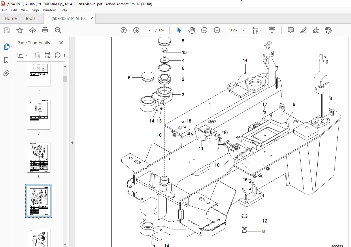
When ordering service parts, specify the correct part number, full description, quantity required, the unit model number and serial number.For your safety and continued proper operation, use only genuine Mustang service parts.
- The model and serial number for this unit are on a tag located on a panel on the front of the cabin. ”Right” and ”left” are determined from a position sitting on the operator’s seat and facing forward.
- Mustang Manufacturing reserves the right to make changes or improvements in the design or construction of any part of the unit without incurring the obligation to install such changes on any previously delivered units.
- Refer to the abbreviations table located on this page for special parts descriptions. Standard attaching hardware torque values are also provided near the back of this manual. Metric torque values shown in the illustrations are in Newton-meters and are converted to foot-pounds by multiplying by 0.738.
- Specific reference numbers, indicating a complete assembly, are circled in some illustrations. A small bag, pictured in some illustrations, indicates a seal kit (seals, o-rings, etc.). In the exploded view parts list, additional information may follow the Reference Number.
IMAGES PREVIEW OF THE MANUAL:
Customer Support: [email protected]
PLEASE NOTE:
- This is the SAME exact manual used by your dealers to fix your vehicle.
- The same can be yours in the next 2-3 mins as you will be directed to the download page immediately after paying for the manual.
- Any queries / doubts regarding your purchase, please feel free to contact [email protected]
S.V