Mustang Manitou 1350R NXT2 1350R NXT2(EU) 1350R NXT2 X-Series 1500R NXT2 1500R NXT2(EU) 1500R NXT2 X-Series Operator’s Manual 50950504 – PDF DOWNLOAD
Original price was: $75.95.$26.95Current price is: $26.95.
Mustang Manitou 1350R NXT2 1350R NXT2 (EU) 1350R NXT2 X-Series 1500R NXT2 1500R NXT2 (EU) 1500R NXT2 X-Series Skid-Steer Loader Operator’s Manual 50950504 – PDF DOWNLOAD
Description
Mustang Manitou 1350R NXT2 1350R NXT2 (EU) 1350R NXT2 X-Series 1500R NXT2 1500R NXT2 (EU) 1500R NXT2 X-Series Skid-Steer Loader Operator’s Manual 50950504 – PDF DOWNLOAD
IMAGES PREVIEW OF THE MANUAL:
FILE DETAILS:
Mustang Manitou 1350R NXT2 1350R NXT2 (EU) 1350R NXT2 X-Series 1500R NXT2 1500R NXT2 (EU) 1500R NXT2 X-Series Skid-Steer Loader Operator’s Manual 50950504 – PDF DOWNLOAD
Language : English
Pages : 136
Downloadable : Yes
File Type : PDF
Size: 35.6 MB
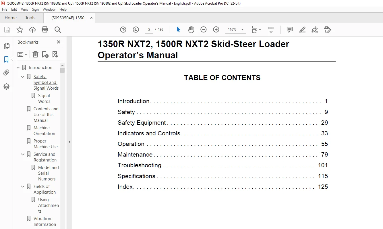
TABLE OF CONTENTS:
Mustang Manitou 1350R NXT2 1350R NXT2 (EU) 1350R NXT2 X-Series 1500R NXT2 1500R NXT2 (EU) 1500R NXT2 X-Series Skid-Steer Loader Operator’s Manual 50950504 – PDF DOWNLOAD
Introduction 7
Safety Symbol and Signal Words 7
Signal Words 7
Contents and Use of this Manual 7
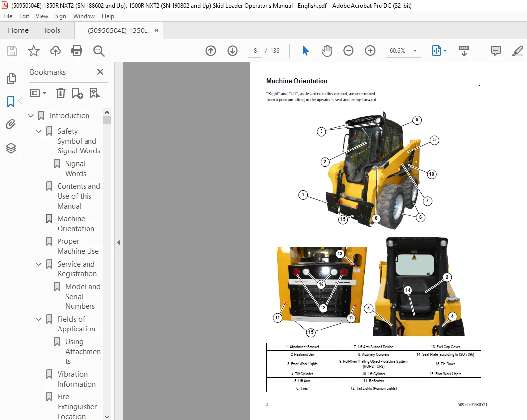
Machine Orientation 8
Proper Machine Use 9
Service and Registration 9
Model and Serial Numbers 9
Fields of Application 10
Using Attachments 10
Vibration Information 12
Fire Extinguisher Location 12
Manufacturer Information 12
Indicator and Operation Symbols 13
Page Intentionally Left Blank 14
Safety 15
Mandatory Safety Shutdown Procedure 15
Safety Reminders 16
Before Starting 16
Additional Safety Equipment 16
During Operation 17
Electrical Energy 19
Maintenance 19
Crystalline Silica Exposure 21
Transporting the Machine 21
Lifting the Machine with a Crane 21
Loading and Transporting the Machine 21
Safety Decals 21
New Decal Application 21
Product and Component Plate Locations 34
a Safety alert / Keep safety devices in place and in working order 29
b Fire hazard / Do not smoke while fueling or servicing the machine Clean debris from the engine compartment to avoid fires Keep fire extinguisher nearby 29
c Run-over hazard / Jump-start the machine only according to the operator’s manual See “Jump- starting” on page 60 29
d Oil injection hazard / Do not use hands to find hydraulic leaks Escaping oil under pressure can penetrate skin Use a piece of cardboard to find leaks 29
e Burn hazard / Allow radiator to cool before removing cap Loosen cap slowly to avoid burns 29
f Suffocation hazard / Operate only in a well-ventilated area 29
a Keep out from under work tool, unless lift arm is supported 29
b No riders! Never use work tool as work platform 29
a Forward tip hazard: Carry load low, do not exceed Rated Operating Load 30
b Fasten seat belt 30
c Side tip hazard: Avoid steep slopes and high-speed turns Travel up and down slopes with heavy end uphill 30
d Crush hazard: Keep out from under lift arm unless lift arm is supported Keep hands, feet and body inside cab when operating 30
a Crush hazard: Keep out from under lift arm unless lift arm is supported 31
b Crush hazard: Hose removal or component failure can cause lift arm to drop Always use lift arm support device when leaving lift arm raised for service 31
c Side tip hazard: Avoid steep slopes and high-speed turns Travel up and down slopes with heavy end uphill 31
d Crush hazard: Keep hands, feet and body inside cab when operating 31
a Check machine before operation according to Operational Checks starting on page 55 Contact dealer (or manufacturer) for information and service parts 32
b Maintain 3-point contact during entry and exit 32
c Inspect work area Avoid all hazards Look in direction of travel Keep children and bystanders away 32
d Start and operate machine only from the operator’s position with the seatbelt fastened 32
e Keep away from power lines; avoid contact 32
f Wear any needed Personal Protective Equipment Do not wear loose clothing while operating or servicing machine 32
SAFETY EQUIPMENT 35
Guards and Shields 35
Operator’s Position 35
Operator’s Seat 35
Seat Belt 35
Upper Torso Restraint (Option) 36
Operator Restraint Bar 36
Safety Interlock System (Hydraloc™) 36
Safety Interlock System Test 36
Parking Brake 37
ROPS/FOPS 37
Rear Window Emergency Exit 37
Lift Arm Support 37
Engage Lift Arm Support 37
Disengage Lift Arm Support 38
Battery Disconnect Switch 38
Indicators and Controls 39
Control Keypad 40
Control Keypad Indicators 40
Control Keypad Buttons 41
Accessory Keypad Indicators/Buttons 42
Optional Lights/Lockout Keypad Indicators/Buttons 43
Information Center Electronic Display 44
Information Center Electronic Display Symbols 45
Information Center Electronic Display Screens 46
A Fuel level 46
B Engine coolant temperature 46
C Accumulated operation time 46
D Amber error condition warning Causes DM1/DM2 errors screen(s) to display See page 42 46
E Red critical error warning Causes DM1/DM2 errors screen(s) to display See page 42 46
F Engine coolant temperature amber warning region Indicates elevated coolant temperature 46
G Engine coolant temperature red stop warning region Indicates serious coolant overheating condition 46
H Fuel level amber warning region Indicates low fuel level 46
I Fuel level red stop region Indicates almost empty fuel tank 46
Controls 48
Ignition Keyswitch 48
Throttle Controls 49
Travel Drive, Lift and Tilt Controls 49
Drive Control (Left T-Bar) 50
A To go forward, push the left T-bar forward 50
B To go in reverse, pull the left T-bar rearward 50
C To turn right, twist the control clockwise 50
D To turn left, twist the control counter-clockwise 50
Lift/Tilt Control (Right T-Bar) 50
A To lower the lift arm, push the right T-bar straight forward 50
B To raise the lift arm, pull the right T-bar straight rearward 50
C To tilt the attachment forward and down, twist the right T-bar clockwise 50
D To tilt the attachment up and back, twist the right T-bar counter-clockwise 50
Drive Control (Left Joystick) 52
A To go forward, push the left joystick forward 52
B To go in reverse, pull the left joystick rearward 52
C To turn right, push the left joystick to the right 52
D To turn left, push the left joystick to the left 52
E To go forward and to the right, push the left joystick forward and to the right 52
F To go rearward and to the right, pull the left joystick rearward and to the right 52
G To go forward and to the left, push the left joystick forward and to the left 52
H To go rearward and to the left, pull the left joystick rearward and to the left 52
Lift/Tilt Control (Right Joystick) 52
A To lower the lift arm, push the right joystick straight forward 52
B To raise the lift arm, pull the right joystick straight back 52
C To tilt the attachment forward and down, move the right joystick to the right 52
D To tilt the attachment up and back, move the right joystick to the left 52
E To lower the lift arm while tilting the attachment forward and down, move the right joystick forward and to the right 52
F To lower the lift arm while tilting the attachment up and back, move the right joystick forward and to the left 52
G To raise the lift arm while tilting the attachment forward and down move the right joystick rearward and to the right 52
H To raise the lift arm while tilting the attachment up and back, move the right joystick rearward and to the left 52
Drive Control (Hand Controls) 54
A To go forward, push both hand controls forward 54
B To go in reverse, pull both hand controls rearward 54
C To turn right, push the left hand control farther forward than the right 54
D To turn left, push the right hand control farther forward than the left 54
E To spin turn clockwise, push the left hand control forward and pull the right hand control rearward 54
F To spin turn counter-clockwise, push the right hand control forward and pull the left hand control rearward 54
Lift/Tilt Control (Foot Controls) 54
A To lower the lift arm, push the front of the left foot pedal down 54
B To raise the lift arm, push the back of the left foot pedal down 54
C To tilt the attachment forward and down, push the front of the right foot pedal down 54
D To tilt the attachment up and back, push the back of the right foot pedal down 54
Lift Arm Float 55
Hydraglide™ Ride Control System (Option) 56
Beacon/Position/Work Lights 56
HVAC (Option) 56
A Cab Heat/Cool: Controls cab heat/cool Press button as desired to set cab heat/cool; subsequent pressings increase heat from low to high LEDs above the button are lit according to the low, medium and high heat settings 56
NOTE: Cab heat/cool requires fan to be activated by pressing button (B) 57
B Fan Speed: Controls cab air circulation fan Press button (B) once for low setting, twice for medium, and three times for high LEDs above the button are lit according to the low, medium and high fan settings Press button (A) a forth time to deac 57
A Windshi eld Wiper: Controls the front windshield wiper on machines equipped with a cab door Press button (A) once for continuous setting, twice for 3 second delay, and three times for 6 second delay LEDs above the button are lit according to the 57
B Rear Window Wiper (EU only): Controls the back window wiper Press button (B) once for continuous setting, twice for 3 second delay, and three times for 6 second delay LEDs above the button are lit according to the selected setting Press button 57
C Windshield Washer: Push and hold button (C) to activate the windshield washer spray and wiper Release the button to stop the spray; wiper continues for 5 seconds 57
D Rear Window Washer (EU only): Push and hold button (C) to activate the rear window washer spray and wiper Release the button to stop the spray; wiper continues for 5 seconds 57
Dome Light 57
Accessory Plug 57
Battery Disconnect Switch 58
Attachment Mounting 58
All-Tach® Hitch 58
Power-A-Tach® System 58
Auxiliary Hydraulic System 60
Auxiliary Hydraulic Couplers 60
Auxiliary Hydraulics Control 60
Operation 61
Before Starting the Engine 61
Operational Checks 61
Cab Entry and Exit 63
Starting the Engine 64
Cold-Starting 64
After Starting 65
Warm Up 65
Run-In Period 65
Stopping the Machine 65
Engine Stalling 66
Parking the Machine 66
Brake Release Operation (Option) 66
Jump-starting 66
Travel Drive Operation 68
Two-Speed Drive (Option) 68
Driving on an Incline 68
Driving over Rough Terrain 68
Transport on Public Roads 68
Transport Hydraulics Lock-out (Option) 68
Lift Arm Operation 68
Attachment Transport Position 69
Lift Arm Float 69
Hydraglide™ Ride Control System (Option) 69
Changing Attachments 70
Connecting Attachments 70
Disconnecting Attachments 71
Connecting Auxiliary Hydraulic Couplings 71
Disconnecting Auxiliary Hydraulic Couplings 72
Self-Leveling (Option) 72
Self-Leveling Cancel 73
Using Buckets 73
Digging with a Bucket 73
Loading a Bucket 74
Dumping a Load onto a Pile 74
Loading Trucks (or Hoppers) 75
Backfilling Holes and Embankments 75
Scraping with a Bucket 76
Grading 76
Using Pallet Forks 77
Safety Instructions When Working with Pallet Forks 77
Transporting Loads Using Pallet Forks 78
Loading and Transporting the Machine on a Transport Vehicle 79
Towing 80
Lifting the Machine Using a Crane or Hoist 80
Diesel Particulate Filter (DPF) Regeneration Procedures (DPF Models) 80
Reset Regeneration 81
Stationary Regeneration 81
A Press the button on the control keypad (page 34) or lift the operator restraint bar to apply the parking brake A checkmark is displayed next to the parking brake symbol (A) 82
B When engine coolant has reached operating temperature (above 140° F / 60° C, a checkmark is displayed next to the coolant temperature symbol (B) 82
C Place throttle controls to the lowest speed setting A checkmark is displayed next to the engine RPM symbol when the engine is running at low idle 82
Forcing Stationary Regeneration 82
DPF Maintenance 82
Camera Observation System 83
Back-Up Alarm 83
Page Left Intentionally Blank 84
Maintenance 85
Maintenance Schedules 86
Maintenance Log 88
General Lubrication 90
Removing Foreign Material 91
Tilting the ROPS/FOPS 91
Raising the ROPS/FOPS 91
Lowering the ROPS/FOPS 91
Lifting the Machine 91
Lowering the Machine 92
Engine Maintenance 92
Engine Access 92
a Pull down on spring pin lock (C, Figure 91) to release pin (D) Lift pin (D) out of the bracket 92
b Swing the radiator outward 92
c When engine maintenance is complete, return the radiator back to the closed position and secure it in place with pin (D) Lock pin (D) in the bracket with spring pin lock (C) 92
Engine Mounting Hardware Inspection 93
Checking Engine Oil Level 93
a Clean the area around the oil fill cap (F) with a clean cloth 93
b Remove fill cap (F) 93
c Add oil through the fill cap opening until the level reaches the “Full” mark 93
d Replace and tighten fill cap (F) 93
Changing Engine Oil and Filter 93
Fuel System Maintenance 94
Adding Fuel 94
Water Separator Maintenance 95
Changing Water Separator Filter 95
Changing Fuel Filter 95
Engine Air Cleaner 96
Changing Air Filter Elements 96
DPF Service (DPF Models) 97
V-Belt Maintenance 97
Cooling System 97
Checking Coolant Level 97
Cleaning Radiator Fins 97
Draining/Flushing Cooling System 98
Hydraulic System 98
Checking Hydraulic Oil Level 98
Changing Hydraulic Oil Filter 99
Changing Hydraulic Oil 99
Hydraulic Hose Maintenance 100
Chaincases 100
Drive Motors 100
Checking and Adding Chaincase Oil 100
Changing Chaincase Oil 100
Drive Chain Tension 101
Seat and Restraint Bar Switches 101
Bucket Cutting Edge 101
Wheel Nuts 101
Tires 101
Mounting Tires 101
Checking Tire Pressure 102
Electrical System 103
Fuses, Relays and Diodes 103
Battery 105
a 0 5 kg (1 lb ) of baking soda in 4 L (1 gal ) of water 105
b 0 5 L (1 pt ) of household ammonia in 4 L (1 gal ) of water 105
Windshield Washer Reservoir 105
Long-Term Storage 105
Before Storage 105
After Storage 106
Final Shutdown / Decommissioning 106
Before Disposal 106
Machine Disposal 106
Dealer Services 106
Troubleshooting 107
Engine Troubleshooting 107
Indicator Lamp Troubleshooting 108
Seal and Hose Troubleshooting 109
Hydraulic System Troubleshooting 109
Hydrostatic Drive System Troubleshooting 112
Electrical Troubleshooting 113
Error Codes 114
Engine Diagnostic Trouble Codes (DTC) 114
THIS PAGE LEFT INTENTIONALLY BLANK 120
Specifications 121
Fluid Capacities/Lubricants 121
Weights 122
Payloads/Capacities 122
Engine 124
Coolant Compound Mixtures 124
Hydraulics 125
Travel Speeds 125
Electrical System 125
Sound Levels 126
Vibration Levels 126
Dimensions 127
Features 128
Common Materials and Densities 129
PAGE INTENTIONALLY LEFT BLANK 130
Index 131
A 131
B 131
C 131
D 131
E 131
F 131
G 132
H 132
I 132
J 132
L 132
M 132
O 132
P 132
R 132
S 132
T 133
U 133
V 133
W 133
PAGE INTENTIONALLY LEFT BLANK 134
DESCRIPTION:
Mustang Manitou 1350R NXT2 1350R NXT2 (EU) 1350R NXT2 X-Series 1500R NXT2 1500R NXT2 (EU) 1500R NXT2 X-Series Skid-Steer Loader Operator’s Manual 50950504 – PDF DOWNLOAD
Contents and Use of this Manual:
This Operator’s Manual provides information about the safe and proper operation and maintenance for the machine. Major points of safe operation and maintenance are detailed in the Safety section of this manual, starting on page 9. This manual also includes general troubleshooting and specification information about the machine.
- Follow the instructions in the Operator’s Manual Safety, Operation and Maintenance chapters, concerning accident prevention regulations, safety and occupational regulations, and machine and traffic regulations. Manitou Group is not liable for injury or damage resulting from the failure to follow these regulations.
- Improper operation, inspection and maintenance of the machine can cause injury or death. Read and understand the contents of this manual COMPLETELY and become familiar with the machine before operating it. It is the owner’s or employer’s responsibility to fully instruct each operator in the proper and safe operation and maintenance of the machine.
- A storage location is provided inside the operator’s compartment for storing this Operator’s Manual. After using this manual, return it to the storage location. This manual is considered a permanent part of the machine and should be with the machine at all times. If the machine is resold, include this operator’s manual as part of the sale. Replace this manual promptly if it becomes damaged, lost or stolen.
- Some illustrations and photos in this manual may show doors, guards and shields open or removed for informational purposes only. BE SURE all doors, guards and shields are in their proper operating positions BEFORE starting the engine to operate the machine. Because of ongoing product improvements, information included in this manual may not exactly match the machine. Manitou Group reserves the right to modify and improve products at any time without notice or obligation.
Questions? Email us: [email protected]
https://vimeo.com/806328867
PLEASE NOTE:
- This is the SAME manual used by the dealers to troubleshoot any faults in your vehicle. This can be yours in 2 minutes after the payment is made.
- Contact us at [email protected] should you have any queries before your purchase or that you need any other service / repair / parts operators manual.
S.V