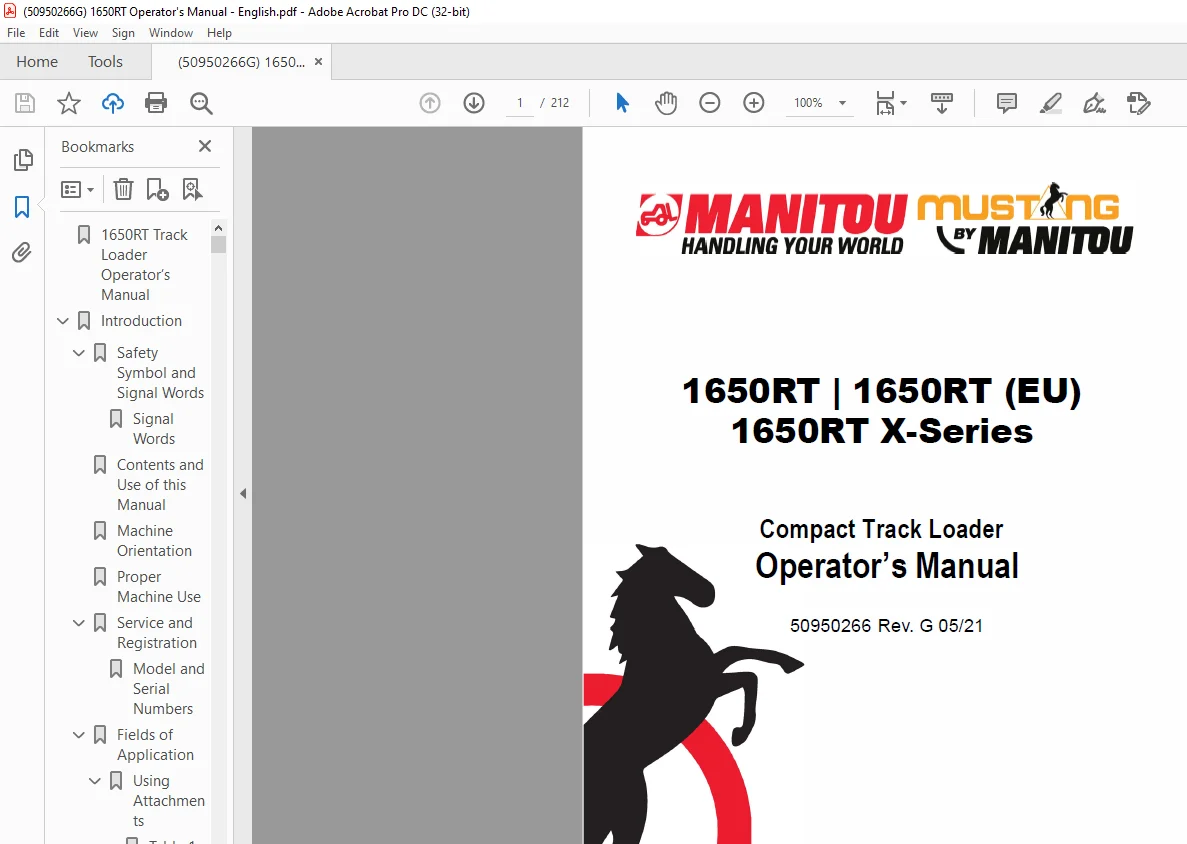
Mustang Manitou 1650RT 1650RT (EU) 1650RT X-Series Compact Track Loader Operator’s Manual 50950266 – PDF DOWNLOAD
Original price was: $86.95.$28.95Current price is: $28.95.
Mustang Manitou 1650RT 1650RT (EU) 1650RT X-Series Compact Track Loader Operator’s Manual 50950266 – PDF DOWNLOAD
Description
Mustang Manitou 1650RT 1650RT (EU) 1650RT X-Series Compact Track Loader Operator’s Manual 50950266 – PDF DOWNLOAD
FILE DETAILS:
Mustang Manitou 1650RT 1650RT (EU) 1650RT X-Series Compact Track Loader Operator’s Manual 50950266 – PDF DOWNLOAD
Language : English
Pages : 212
Downloadable : Yes
File Type : PDF
Size: 31.2 MB
DESCRIPTION:
Mustang Manitou 1650RT 1650RT (EU) 1650RT X-Series Compact Track Loader Operator’s Manual 50950266 – PDF DOWNLOAD
Contents and Use of this Manual:
This Operator’s Manual provides information about the safe and proper operation and maintenance for the machine. Major points of safe operation and maintenance are detailed in the Safety chapter of this manual.
- This manual also includes general troubleshooting and specification information about the machine.
- Follow the instructions in the Safety, Operation, and Maintenance chapters concerning accident prevention regulations, safety and occupational regulations, and machine and traffic regulations.
- Manitou Group is not liable for damage resulting from the failure to follow these regulations. It is the owner’s or employer’s responsibility to fully instruct each operator in the proper and safe operation and maintenance of the machine.
- A storage location is provided behind the operator’s seat for storing the Operator’s Manual. After using the manual, return it to the storage container.
- The Operator’s Manual is considered a permanent part of the machine and should be with the machine at all times. If the machine is resold, include this operator’s manual as part of the sale.
- Replace the Operator’s Manual promptly if it becomes damaged, lost, or stolen. Some illustrations in this manual may show doors, guards and shields open or removed for illustrative purposes only. BE SURE all doors, guards and shields are in their proper operating positions BEFORE starting the engine to operate the machine.
- Because of ongoing product improvements, information included in this manual may not exactly match the machine. Manitou Group reserves the right to modify and improve products at any time without notice or obligation.
Service and Registration :
- When ordering service parts, provide complete information about the part and he quantity required. Also provide the model and serial numbers of the machine. For your safety and continued proper operation, use only genuine service parts. Record the model and serial numbers in the spaces below for quick reference.
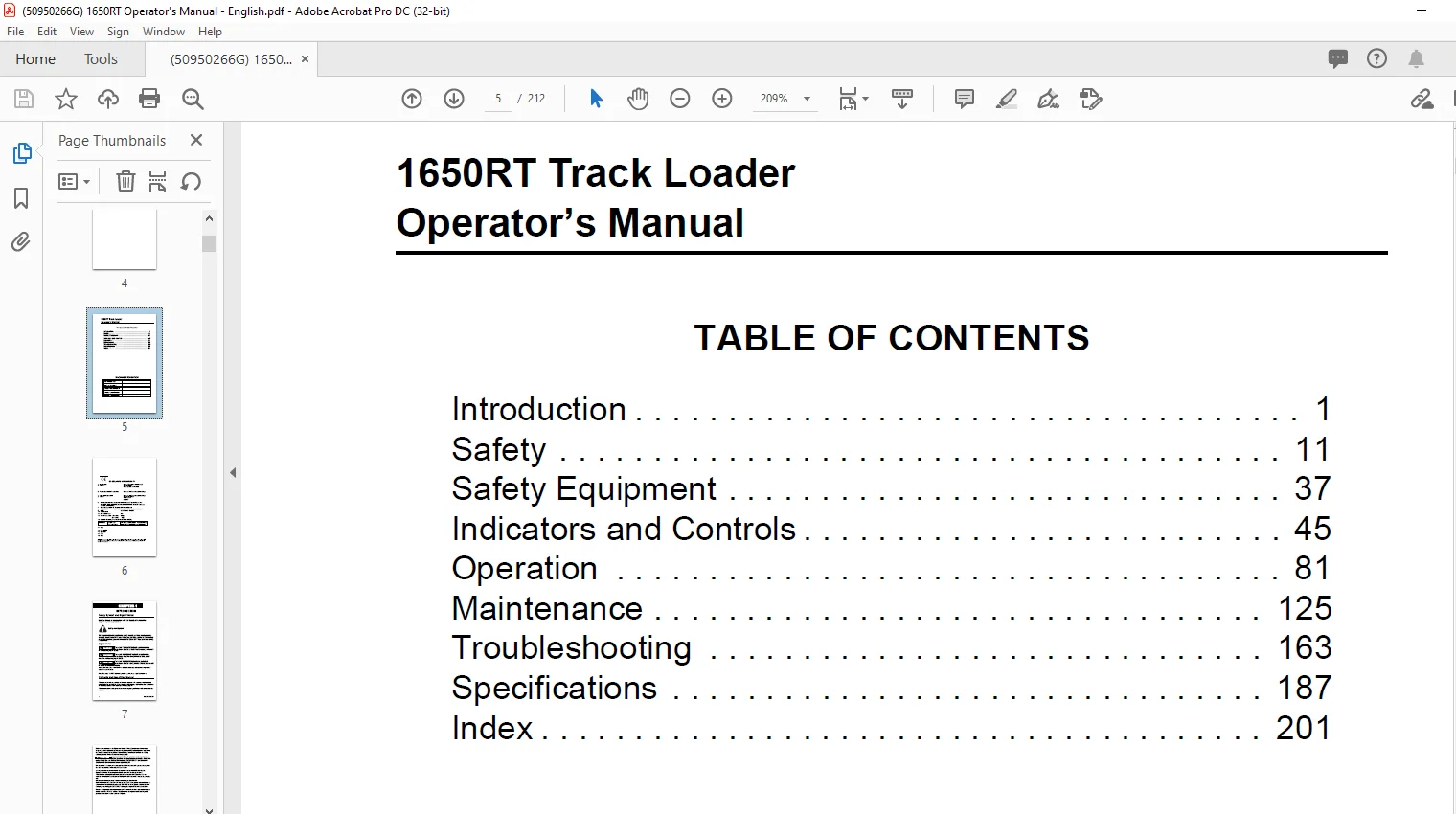
TABLE OF CONTENTS:
Mustang Manitou 1650RT 1650RT (EU) 1650RT X-Series Compact Track Loader Operator’s Manual 50950266 – PDF DOWNLOAD
1650RT Track Loader Operator’s Manual 5
Introduction 7
Safety Symbol and Signal Words 7
Signal Words 7
Contents and Use of this Manual 7
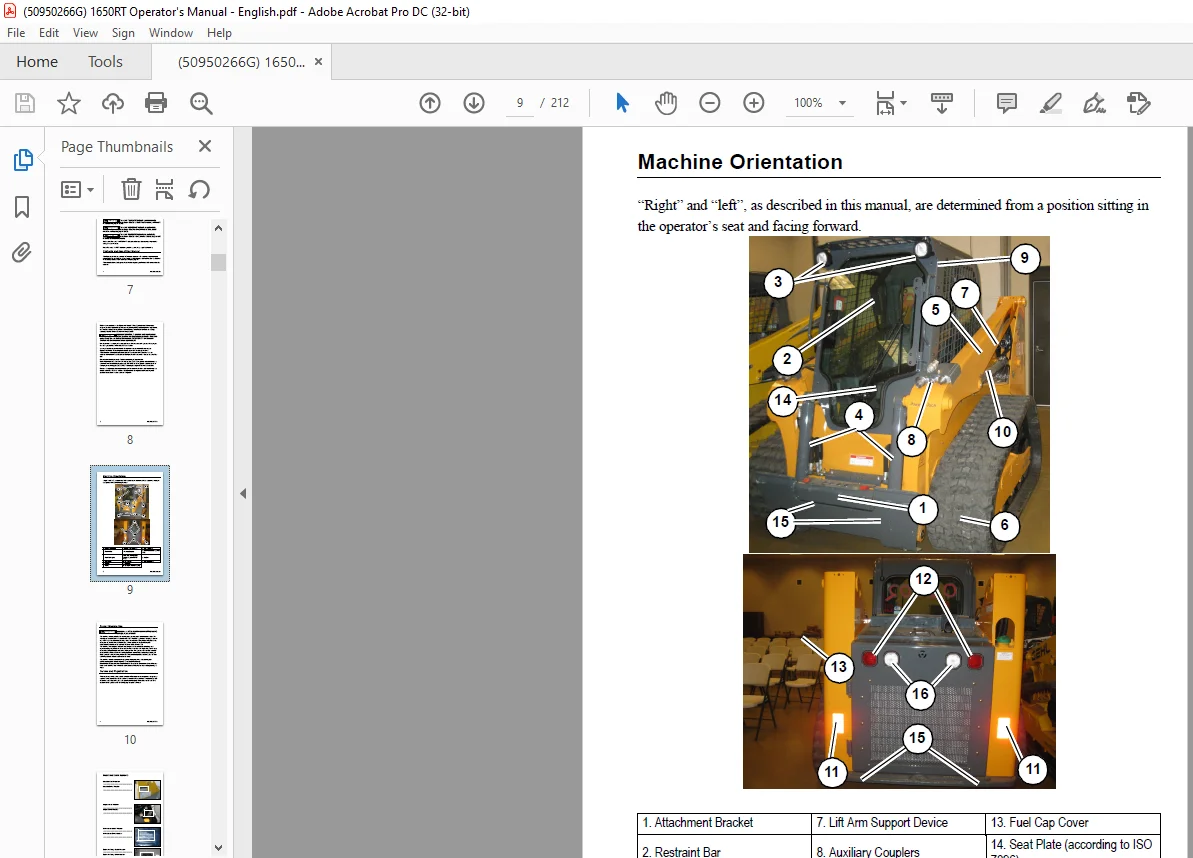
Machine Orientation 9
Proper Machine Use 10
Service and Registration 10
Model and Serial Numbers 11
Fields of Application 12
Using Attachments 12
Table 1: Fields of Application 12
Vibration Information 13
1 Train operators: 14
2 Choose proper equipment for the job: 14
3 Maintain the worksite: 14
4 Maintain equipment Check that seat suspension and all controls work smoothly and properly 14
Fire Extinguisher Location 14
Figure 1 – Fire Extinguisher Location 14
Manufacturer Information 14
Indicator and Operation Symbols 15
Safety 17
Mandatory Safety Shutdown Procedure 18
1 Move the drive controls to their neutral position 18
2 Lower the lift arm and attachment completely If the lift arm must be left in the raised position, BE SURE to properly engage the lift arm support device See “Lift Arm Support” on page 44 18
3 Move the lift/tilt and auxiliary hydraulic controls to their neutral positions 18
4 Move the throttle to the low idle position Allow the engine to idle for five minutes if the engine was operated under full load 18
5 Apply the parking brake and lock out work hydraulics by raising the operator restraint bar 18
6 Shut off the engine and remove the key 18
7 Before exiting, move the lift/tilt control(s) to verify that the controls do not cause movement of the lift arm and hitch 18
8 Always turn the switch to the battery disconnect switch to the “OFF” position when parking the machine inside an enclosure 18
Safety Reminders 18
Before Starting 18
Additional Safety Equipment 20
During Operation 20
Electrical Energy 24
Maintenance 25
Crystalline Silica Exposure 28
Transporting the Machine 28
Lifting the Machine with a Crane 28
Loading and Transporting the Machine 29
Safety Decals 29
New Decal Application 29
Figure 2 – ANSI-Style Safety and Information Decal Locations 30
Figure 3 – ISO-Style (Used Internationally) Safety and Information Decal Locations 36
Product and Component Plate Locations 42
1 Operator protective system plate: with, e g , model, certification and operator protective system serial number 42
2 Seat plate according to ISO 7096 42
3 Product plate: with Product Identification Number and, e g , model/type designation 42
4 Engine plate: with, e g , type designation, product and serial numbers 42
5 Component plate hydrostatic pump: with, e g , product and serial numbers 42
6 Component plate drive motor: with, e g , product and serial numbers 42
Safety Equipment 43
Guards and Shields 43
Operator’s Position 43
Operator’s Seat 43
Figure 4 – Operator’s Seat Horizontal Adjustment 43
Figure 5 – Operator’s Seat Suspension Adjustment 44
Seat Belt 44
Figure 6 – Seat Belt / Upper Torso Restraint 44
Upper Torso Restraint (Option) 45
Operator Restraint Bar 45
Figure 7 – Operator Restraint Bar 45
Figure 8 – Restraint Bar Lowered Position Adjustment 45
Safety Interlock System (Hydraloc™) 46
Safety Interlock System Test 46
Parking Brake 47
Figure 9 – Parking Brake Button 47
ROPS/FOPS 47
Rear Window Emergency Exit 47
Figure 10 – Rear Window Emergency Exit 47
Lift Arm Support 48
Engage Lift Arm Support 48
1 Empty and remove the attachment (See “Connecting Attachments” on page 98) 48
2 Bring the machine to a complete stop on a level surface 48
3 Lower the lift arm fully 48
4 Stop the engine 48
5 Have an assistant remove the lift arm support from its storage location on the left side of the machine Remove lynchpin (S, Figure 11) holding lift arm support (T) up against the lift arm Allow lift arm support (T) device to pivot down into cont 48
Figure 11 – Lift Arm Support Storage Lynchpin Removal 48
6 Restart the engine 48
7 Use the lift control to raise the lift arm until lift arm support (T, Figure 12) drops over the end of the lift cylinder and around the cylinder rod 49
Figure 12 – Lift Arm Support Engaged 49
8 Slowly lower the lift arm until the free end of the support device contacts the top end of the lift cylinder (U) 49
9 Check the support device to ensure it is secure against the cylinder end 49
10 Stop the engine 49
11 Move the lift control to verify the control does not cause the lift arm to move 49
12 Unfasten the seat belt, remove the ignition key and take it with you Exit the machine using the hand-holds 49
Disengage Lift Arm Support 49
1 Start the engine 49
2 Raise the lift arm fully 49
3 Stop the engine 49
4 Verify that the lift arm is being held in the raised position by the safety interlock system 49
5 Have an assistant raise lift arm support (T, Figure 13) until it contacts the lift arm Reinstall lynchpin (S) through post (V) on the lift arm to secure lift arm support (T) in the storage position 49
Figure 13 – Lift Arm Support Storage Position 49
6 Fold lynchpin ring (W) over post (V) to lock lynchpin in place 49
Battery Disconnect Switch 50
Figure 14 – Battery Disconnect Switch 50
Indicators and Controls 51
Figure 15 – Controls (Hand/Foot Control Option Shown) 51
Control Keypad 52
Control Keypad Indicators 52
Table 2: Control Keypad Indicators 52
Figure 16 – Control Keypad Indicators 52
Control Keypad Buttons 54
Figure 17 – Control Keypad Buttons 54
Table 3: Control Panel Buttons 54
Accessory Keypad Indicators/Buttons 55
Table 4: Accessory Keypad Buttons 55
Figure 18 – Accessory Keypad Indicators/Buttons 55
Optional Lights/Lockout Keypad Indicators/Buttons 56
Table 5: Optional Road Lights Keypad Buttons 56
Figure 19 – Road Lights Keypad Indicators/Buttons 56
Information Center Electronic Display 57
Figure 20 – Information Center Electronic Display 57
Information Center Electronic Display Symbols 58
Table 6: Symbols Descriptions 58
Information Center Electronic Display Screens 60
Table 7: Status, Maintenance and Error Code Screens 60
A Fuel level 60
B Engine coolant temperature 60
C Accumulated operation time 60
D Amber error condition warning Causes DM1/DM2 errors screen(s) to display See page 56 60
E Red critical error warning Causes DM1/DM2 errors screen(s) to display See page 56 60
F Engine coolant temperature amber warning region Indicates elevated coolant temperature 60
G Engine coolant temperature red stop warning region Indicates serious coolant overheating condition 60
H Fuel level amber warning region Indicates low fuel level 60
I Fuel level red stop region Indicates almost empty fuel tank 60
Controls 63
Ignition Keyswitch 63
Figure 21 – Ignition Keyswitch 63
Throttle Controls 64
Figure 22 – Throttle Knob 64
Figure 23 – Throttle Pedal 64
Travel Drive, Lift and Tilt Controls 65
Figure 24 – T-Bar Hand Controls 65
Table 8: T-Bar Controls 65
Figure 25 – Drive Control (Left T- Bar) 66
A To go forward, push the left T-bar forward 66
B To go in reverse, pull the left T-bar rearward 66
C To turn right, twist the control clockwise 66
D To turn left, twist the control counter-clockwise 66
Figure 26 – Lift/Tilt Control (Right T- Bar) 67
A To lower the lift arm, push the right T-bar straight forward 67
B To raise the lift arm, pull the right T-bar straight rearward 67
C To tilt the attachment forward and down, twist the right T-bar clockwise 67
D To tilt the attachment up and back, twist the right T-bar counter- clockwise 67
Figure 27 – Joystick Hand Controls 68
Table 9: Joystick Controls 68
Figure 28 – Drive Control (Left Joystick) 69
A To go forward, push the left joystick forward 69
B To go in reverse, pull the left joystick rearward 69
C To turn right, push the left joystick to the right 69
D To turn left, push the left joystick to the left 69
E To go forward and to the right, push the left joystick forward and to the right 69
F To go rearward and to the right, pull the left joystick rearward and to the right 69
G To go forward and to the left, push the left joystick forward and to the left 69
H To go rearward and to the left, pull the left joystick rearward and to the left 69
Figure 29 – Lift/Tilt Control (Right Joystick) 69
A To lower the lift arm, push the right joystick straight forward 69
B To raise the lift arm, pull the right joystick straight back 69
C To tilt the attachment forward and down, move the right joystick to the right 69
D To tilt the attachment up and back, move the right joystick to the left 69
E To lower the lift arm while tilting the attachment forward and down, move the right joystick forward and to the right 70
F To lower the lift arm while tilting the attachment up and back, move the right joystick forward and to the left 70
G To raise the lift arm while tilting the attachment forward and down move the right joystick rearward and to the right 70
H To raise the lift arm while tilting the attachment up and back, move the right joystick rearward and to the left 70
Figure 30 – Hand and Foot Controls 71
Table 10: Hand and Foot Controls 71
Figure 31 – Drive Control (Hand Controls) 72
A To go forward, push both hand controls forward 72
B To go in reverse, pull both hand controls rearward 72
C To turn right, push the left hand control farther forward than the right 72
D To turn left, push the right hand control farther forward than the left 72
E To spin turn clockwise, push the left hand control forward and pull the right hand control rearward 72
F To spin turn counter-clockwise, push the right hand control forward and pull the left hand control rearward 72
Figure 32 – Lift/Tilt Control (Foot Controls) 73
A To lower the lift arm, push the front of the left foot pedal down 73
B To raise the lift arm, push the back of the left foot pedal down 73
C To tilt the attachment forward and down, push the front of the right foot pedal down 73
D To tilt the attachment up and back, push the back of the right foot pedal down 73
Two-Speed Drive 73
Figure 33 – Two-Speed Drive Control Button 74
Lift Arm Float 75
Figure 34 – Lift/Tilt Control (Foot Controls) 75
1 Lower the attachment to the ground 75
2 Push Right T-Bar (B) all the way forward (Figure 26) into the detent (“float”) position This position allows the lowered lift arm to “float” while traveling over changing ground conditions 75
3 To remove lift arm from the detent (“float”) position, pull the Right T-Bar (B) out of the detent position This returns the lift arm to normal operation 75
1 Lower the attachment to the ground 75
2 Press button (A, Figure 34) to activate float: 75
1 Lower the attachment to the ground 75
2 To place the lift arm in the detent (“float”) position, use your toes to push the left pedal all the way down (A) into the detent This position allows the lowered lift arm to “float” while traveling over changing ground conditions 76
Hydraglide™ Ride Control System (Option) 77
Figure 35 – Hydraglide™ Control Button 77
Beacon/Position/Work Lights 78
Figure 36 – Beacon/Position/Work Lights Button 78
HVAC (Option) 78
A Cab Heat/Cool: Controls cab heat/cool Press button as desired to set cab heat/cool; subsequent pressings increase heat from low to high LEDs above the button are lit according to the low, medium and high heat settings 78
Figure 37 – Heater/Fan Buttons 78
NOTE: Cab heat/cool requires fan to be activated by pressing button (B) 78
B Fan Speed: Controls cab air circulation fan Press button (B) once for low setting, twice for medium, and three times for high LEDs above the button are lit according to the low, medium and high fan settings Press button (A) a forth time to deac 78
Figure 38 – Windshield Wiper/ Washer Buttons 79
A Windshield Wiper: Controls the front windshield wiper on machines equipped with a cab door Press button (A) once for continuous setting, twice for 3 second delay, and three times for 6 second delay LEDs above the button are lit according to the 79
B Rear Window Wiper (EU only): Controls the back window wiper Press button (B) once for continuous setting, twice for 3 second delay, and three times for 6 second delay LEDs above the button are lit according to the selected setting Press button 79
C Windshield Washer: Push and hold button (C) to activate the windshield washer spray and wiper Release the button to stop the spray; wiper continues for 5 seconds 79
D Rear Window Washer (EU only): Push and hold button (C) to activate the rear window washer spray and wiper Release the button to stop the spray; wiper continues for 5 seconds 79
Dome Light 79
Figure 39 – Dome Light 79
Accessory Plug 80
Figure 40 – Accessory Plug 80
Battery Disconnect Switch 80
Figure 41 – Battery Disconnect Switch 80
Attachment Mounting 81
All-Tach® Hitch 81
Figure 42 – All-Tach® Hitch 81
Figure 43 – Hitch Locking Pins 81
Power-A-Tach® System 82
Figure 44 – Power-A-Tach® Control Buttons 82
Figure 45 – Power-A-Tach® Hitch 82
Activating The Warming Circuit 83
Table 11: Warming Circuit and Power-A-Tach Latching Pin Operation 83
Figure 46 – Hitch Locking Pins 83
Auxiliary Hydraulic System 84
Auxiliary Hydraulic Couplers 84
Figure 47 – Auxiliary Hydraulics Couplers 84
Auxiliary Hydraulics Control 85
Figure 48 – Auxiliary Hydraulics Control Rocker Switch 85
High-Flow Auxiliary Hydraulic Control (Option) 86
Figure 49 – High-Flow Control Buttons 86
Operation 87
Before Starting the Engine 87
Operational Checks 87
Table 12: Pre-Start Checks 87
Table 13: Checks During Operation 88
Cab Entry and Exit 89
Figure 50 – Cab Entry/Exit Handles/Steps 89
Figure 51 – Cab Exterior Door Handle 89
Figure 52 – Cab Interior Door Handle 90
Figure 53 – Cab Door Electrical Connection 90
Starting the Engine 91
1 If the machine is equipped with the optional battery disconnect switch, check that switch is the “ON” position See “Battery Disconnect Switch” on page 76 91
2 Carefully step up onto the back of the bucket or attachment and grasp the hand-holds enter the operator’s compartment and sit in the operator’s seat Adjust the seat as required See “Operator’s Seat” on page 39 91
3 Close the door, if so equipped Perform the seat switch safety interlock test on page 42 91
4 Fasten the seat belt(s) See “Fastening/Unfastening the Seat Belt” on page 40 91
5 Lower the operator restraint bar 91
6 Place the lift/tilt, drive and auxiliary hydraulic controls into the neutral position 91
7 Make sure no persons are hazardously close to the machine 91
8 Turn the ignition key one detent clockwise to the ON/RUN position If the engine is cold, the pre-heat () indicator activates For information about starting in colder ambient temperatures, see “Cold- Starting” on page 86 91
Figure 54 – Ignition Keyswitch 91
9 When the pre-heat () indicator goes out, turn the ignition key all the way clockwise to the START position to engage the starter 91
Cold-Starting 92
After Starting 93
1 Check that the charge () and oil pressure () indicators go out after the engine starts 93
2 Press the parking brake button on the control keypad to release the parking brake 93
Figure 55 – Parking Brake Button 93
3 Perform restraint bar safety interlock system test on page 42 93
4 Check for proper steering operation 93
5 Check for excessively smoky exhaust (“Engine Troubleshooting” on page 163): 93
Warm Up 94
1 After starting, allow the engine to run at low idle with no load for a minimum of 5 minutes without operating the drive, lift, tilt or auxiliary functions 94
2 Run the engine at 1800 rpm with no load for 5 minutes 94
3 Raise the lift arm so the attachment is off the ground 94
4 Extend and retract each of the cylinders several times with no load 94
5 Travel slowly forward and backward several times 94
6 In cold weather, tilt the attachment all the way forward and keep it there for 20-25 seconds Repeat this step until the attachment tilt speed is normal 94
Run-In Period 94
Stopping the Machine 94
Engine Stalling 94
Parking the Machine 95
Jump-starting 95
1 Turn the ignition keyswitches of both machines to the OFF position Be sure the controls in both machines are in the neutral position and the machines are NOT touching each other If the machine with the booster battery has a drive transmission, p 96
Figure 56 – Battery Locations 96
2 Open the engine compartment to provide access to the discharged battery (Figure 56) If the machine is equipped with a battery disconnect switch (see “Battery Disconnect Switch” on page 76), be sure the switch is in the ON position 96
3 Route the jumper cables so that they cannot catch on any moving objects or components and connect the positive jumper cable to the positive (+) terminal (A, Figure 57) on the discharged battery 96
4 Connect the other end of the positive jumper cable to the positive (+) terminal (B) on the booster battery 96
Figure 57 – Booster Battery Connection 96
5 Connect the negative jumper cable to the negative (-) terminal (C) on the booster battery 96
6 Connect the other end of the negative (-) jumper cable to an unpainted frame surface (D) inside the engine compartment of the machine with the discharge battery Connect the cable as far as possible away from the battery 96
7 Start the machine with the discharged battery See “Starting the Engine” on page 85 If the engine does not start immediately, stop cranking after 10 seconds and repeat starting procedure after approximately 30 seconds 97
8 Once the machine with the discharged battery is running, disconnect the jumper cables in reverse order of connection Be careful not to short the jumper cables together when disconnecting 97
9 Run the machine for at least 30 minutes to re-charge the battery 97
Travel Drive Operation 97
Two-Speed Drive 97
Driving on an Incline 98
Driving over Rough Terrain 98
Transport on Public Roads 98
Transport Hydraulics Lock-out (Option) 98
Figure 58 – Hydraulics Lock-out Option Button 98
Rubber Track Use Cautions and Tips 98
Sprocket Tooth Wear and Track Life 101
Figure 59 – Sprocket Tooth Wear Gauge 101
Lift Arm Operation 102
Attachment Transport Position 102
Figure 60 – Transport Position 102
Lift Arm Float 102
Hydraglide™ Ride Control System 103
Changing Attachments 104
Connecting Attachments 104
1 In an open, level area, place the attachment lock into the unlocked position (Figure 61): 104
Figure 61 – Attachment Hitch Unlocked 104
2 Tilt the attachment plate forward and drive the machine straight forward toward the back of the attachment 104
3 Lower the lift arm so tabs (J) on the top of the attachment plate are aligned just under the hooks on the back of the attachment 104
4 Tilt the attachment plate back until tabs (J) on the top of the attachment plate are engaged against the hooks on the back of the attachment 104
5 Raise the lift arm slightly until the attachment is hanging from the hooks on the back of the attachment and tabs (J) are firmly inserted into the hooks Tilt the attachment plate back, if necessary, so the back of the attachment is resting flat a 104
6 Place the attachment lock into the locked position (Figure 62): 105
Figure 62 – Attachment Hitch Locked 105
7 Make sure the locking pins (F, Figure 63) are fully engaged down through the holes in the attachment 105
Figure 63 – Hitch Locking Pins 105
Disconnecting Attachments 106
1 Empty the attachment and drive to an open, level area to disconnect the attachment 106
2 Lower the attachment to the ground 106
3 Place the attachment lock into the unlocked position (Figure 64): 106
Figure 64 – Attachment Hitch Unlocked 106
4 Lower the lift arm until tabs (J) on top of the attachment plate disengage out of hooks (K) on the back of the attachment 106
5 Look behind you for bystanders and obstacles Drive straight back in reverse away from the attachment 106
Connecting Auxiliary Hydraulic Couplings 107
1 Empty the attachment and lower it to the ground 107
2 Shut off the engine With the ignition on, but the engine off, move the auxiliary hydraulics control rocker switch (F, Figure 65) on the right T-bar, joystick or hand control back and forth to relieve pressure in the auxiliary hydraulics circuit 107
Figure 65 – Auxiliary Hydraulics Control Rocker Switch 107
3 Turn off the ignition Remove the ignition key and take it with you 107
4 Raise the safety bars/arm rests and exit the machine using the hand holds 107
5 Clean the hydraulic connections on the hoses and the connections 107
6 Relieve any residual pressure remaining in the auxiliary hydraulics circuit by pushing the attachment coupler firmly into the auxiliary coupler (Figure 66) 107
Figure 66 – Auxiliary Hydraulics Couplers 107
7 Continue to push the hose connections firmly onto the auxiliary hydraulic connections until they snap into place 107
Disconnecting Auxiliary Hydraulic Couplings 108
1 Empty the attachment and lower it to the ground 108
2 Shut off the engine, but do not turn off the ignition Move the auxiliary hydraulics control rocker switch (F, Figure 67) on the right T-bar, joystick or hand control back and forth to relieve pressure in the auxiliary hydraulics circuit 108
Figure 67 – Auxiliary Hydraulics Control Rocker Switch 108
3 Turn off the ignition Remove the ignition key and take it with you 108
4 Raise the safety bars/arm rests and exit the machine using the hand holds 108
5 Push on the hose connection locking rings until the hose connections release 108
Self-Leveling (Option) 109
Figure 68 – Self-Leveling Operation 109
Self-Leveling Cancel 110
Figure 69 – Self-Leveling Cancel Button 110
Using Buckets 110
Digging with a Bucket 111
1 (Figure 70) Approach the digging site with the lift arm slightly raised Tilt the bucket forward until the cutting edge contacts the ground 111
Figure 70 – Digging 111
2 Tilt the cutting edge of the bucket down at an angle appropriate for ground hardness 111
3 Drive forward slowly, digging into the ground with the cutting edge of the bucket and gradually lower the lift arm 111
4 When the bucket is full, raise the bucket and tilt it back and back away from the material 111
Loading a Bucket 112
1 (Figure 71) Lower the bucket to the ground 112
Figure 71 – Loading a Bucket 112
2 Tilt the bucket slightly forward so the bucket cutting edge is pointing slightly down into the ground 112
3 Drive forward until the bucket is filled with material Adjust the bucket tilt as needed to remove an even layer of ground and to reduce tire slip 112
4 Tilt the bucket back and raise it to scoop up material 112
5 Reduce engine speed and back out of the material 112
6 Set the bucket to transport position See “Attachment Transport Position” on page 96 112
Loading Trucks (or Hoppers) 113
Figure 72 – Dumping into a Truck (or Hopper) 113
1 (Figure 72) Approach the truck and stop, allowing for clearance to raise the lift arm and loaded bucket, and raise the bucket until the lower edge of the bucket clears the truck bed 113
2 Drive slowly forward and stop with the bucket over the inside of the truck 113
3 Tilt the bucket forward and dump the material into the truck bed 113
4 When the truck is half-loaded, use the bucket to spread the load evenly 113
5 Back away from the truck while tilting the bucket back and lowering the lift arm 113
Figure 73 – Loading Trucks 113
Backfilling Holes and Embankments 114
1 (Figure 74) Lower the bucket a few inches from the ground Slowly drive forward until the front edge of the bucket extends halfway over the edge of the hole or embankment 114
Figure 74 – Backfilling 114
2 Tilt the bucket forward to dump the material 114
3 Tilt back and raise the bucket Inspect the hole/ embankment for proper filling 114
4 Continue to dump material as necessary for proper fill 114
5 Back away from the embankment while tilting the bucket back and lowering the lift arm 114
Grading 115
1 (Figure 75) Raise the bucket slightly and tilt it forward 115
Figure 75 – Grading without Float 115
2 Release material from the bucket while traveling forward 115
3 Tilt the bucket forward and adjust the lift arm height until the cutting edge is slightly above the ground 115
4 Drive in reverse, smoothing the material released in step 2 with the front edge of the bucket 115
1 (Figure 76) Lower the bucket to the ground 116
Figure 76 – Grading Using Float 116
2 Activate the lift arm float See “Lift Arm Float” on page 96 for information about the float feature 116
3 Tilt the bucket forward so it stands on the cutting edge at a 30°-45° degree angle to the surface being leveled 116
4 Drive in reverse, dragging the floating bucket Adjust the tilt angle of the bucket while driving in reverse to control the spread of the material 116
Using Pallet Forks 117
Safety Instructions When Working with Pallet Forks 117
Transporting Loads Using Pallet Forks 119
1 Stop the machine immediately in front of the material 119
2 Position the fork arms parallel to the ground 119
3 Make sure the fork arms are adjusted as far apart as possible, as allowed by the load, and are both the same distance away from the center-line of the load 119
4 Adjust the height of the fork arms to fit the lifting area at the bottom of the pallet 119
5 Drive slowly and carefully forward until the fork frame contacts the material 119
6 Make sure the pallet is evenly and safely positioned on the pallet fork arms 119
7 Apply the parking brake 119
8 Slowly raise the pallet forks Do not raise the pallet forks any higher than required Make sure to not exceed pallet fork load center and/or lifting capacity 119
9 Lower the load immediately if you are unsure of the load, the equipment, or in case of any unsafe circumstances 119
10 Tilt the pallet fork frame back slightly, to help retain the load 119
11 Make sure the area around and behind the machine is clear of bystanders and obstacles 119
12 Slowly and carefully drive in reverse and lower the pallet forks to transport position (“Attachment Transport Position” on page 96), when it is safe to do so 119
13 Carry the load as low as safely possible during transport Observe minimum ground clearance Refer to “Attachment Transport Position” on page 96 119
14 Drive slowly and carefully forward straight toward the place where the load will be set down 119
15 Raise the pallet forks slightly above where the load will be placed 120
16 Tilt the pallet forks as needed to level the fork arms 120
17 Carefully drive slowly forward until the load is positioned precisely above where the load will be placed Use care when aligning the load with a stack 120
18 Slowly and carefully lower the lift arm until the load is placed 120
19 Make sure the fork arms are no longer bearing weight and are free to be retracted 120
20 Make sure the area around and behind the machine is clear of bystanders and obstacles 120
21 Slowly and carefully drive in reverse away from the placed load until the lift arm can be lowered to transport position See “Attachment Transport Position” on page 96 120
22 Slightly tilt the pallet fork frame backwards 120
Loading and Transporting the Machine on a Transport Vehicle 121
1 Park the transport vehicle on a level surface Block the tracks on the transport vehicle at the front and rear 121
2 Before starting, check the engine oil level The oil level must be at the “Full” mark on the dipstick Add oil if needed See “Checking Engine Oil Level” on page 137 121
3 Start the engine and raise the hitch plate/attachment enough so that it will not touch the loading ramps 121
4 Slowly and carefully drive in reverse up the ramp onto the transport vehicle 122
5 Position the machine at the lowest possible position on the transport platform, with the center of gravity of the load over centerline of the transport vehicle 122
6 Lower the hitch plate/attachment to the transport platform, turn off the engine and remove the key 122
7 Raise the operator restraint bar to lock out the hydraulic functions If applicable, close the cab door and lock it Do not allow anyone to stay in the cab 122
8 Fasten the machine to the hauling vehicle at the points indicated by the tie-down decals (Figure 77) 122
Figure 77 – Tie-Down Point Identifier 122
9 Place blocks in front and behind tracks to prevent movement 122
10 Measure the clearance height of the machine and transport vehicle Post the clearance height in the cab of the transport vehicle 122
Towing 122
Lifting the Machine Using a Crane or Hoist 123
1 If a bucket is attached, make sure it is emptied If pallet forks are attached, remove any load from the pallet forks 123
2 Raise the arm rests/safety bars to apply the parking brake and lock out the hydraulic functions 123
3 Turn off the engine and remove the ignition key Close the doors and the engine cover Do not allow anyone to stay in the cab 123
4 Using suitable lift equipment, hook into the lift kit lifting points Adjust the length of the slings or chains so the machine is level when lifted 123
5 Center the hoist over the ROPS/FOPS To prevent shock loading of the equipment and excessive swinging, slowly lift the machine off the ground Perform all movements slowly and gradually As needed, use a tag line to help position the machine and k 123
Diesel Particulate Filter (DPF) Regeneration Procedures 124
Reset Regeneration 125
Figure 78 – Reset Regeneration In-Progress 125
Figure 79 – Reset Regeneration Inhibit Button 125
Stationary Regeneration 126
Figure 80 – Stationary Regeneration Request Screen 126
Figure 81 – Stationary Regeneration 126
1 Park the machine in a safe, well-ventilated location away from flammable materials 126
2 The following conditions need to be met before stationary regeneration continues: 126
A Press the button on the control keypad (page 48) or lift the operator restraint bar to apply the parking brake A checkmark is displayed next to the parking brake symbol (A) 126
B When engine coolant has reached operating temperature (above 140° F / 60° C, a checkmark is displayed next to the coolant temperature symbol (B) 126
C Place throttle controls to the lowest speed setting A checkmark is displayed next to the engine RPM symbol when the engine is running at low idle 126
3 When all three checkmarks (A, B & C) are displayed on the Stationary Regeneration screen, press and hold the button (Z) until the Stationary Regeneration In-Progress screen displays (Figure 82) 127
Figure 82 – Stationary Regeneration In-Progress Screen 127
Forcing Stationary Regeneration 127
Figure 83 – Forcing Stationary Regeneration 127
DPF Maintenance 128
Figure 84 – Stationary Regeneration In-Progress Screen 128
Camera Observation System 128
Back-Up Alarm 130
Maintenance 131
Maintenance Schedules 133
Table 14: Inspection, Checks and Cleaning 133
Table 15: Leakage Check 134
Table 16: Lubrication and Filter Changes 134
Table 17: Functional Check 134
Maintenance Log 135
Table 18: Maintenance Log 135
General Lubrication 138
Removing Foreign Material 139
Tilting the ROPS/FOPS 139
Raising the ROPS/FOPS 139
1 Perform the “Mandatory Safety Shutdown Procedure” on page 14 139
Figure 85 – ROPS/FOPS Anchor Hardware 139
2 Remove hardware (A, Figure 85) at the front of the ROPS/FOPS 139
3 Tilt the ROPS/FOPS up and back, moving the control handles out of the way Tilt the ROPS/FOPS back slowly, until locking mechanism (B, Figure 86) locks the ROPS/FOPS in the raised position 140
Figure 86 – ROPS/FOPS Lock Mechanism 140
Lowering the ROPS/FOPS 140
1 Lift the ROPS/FOPS slightly while pulling lock mechanism release (C, Figure 87) toward the front 140
Figure 87 – ROPS/FOPS Lock Mechanism Release 140
2 Lower the ROPS/FOPS slowly onto the chassis, moving the control handles out of the way 140
3 Secure the ROPS/FOPS in the lowered position with anchor hardware (A, Figure 85) Torque to 43 Nm (32 lb -ft ) 140
Lifting the Machine 141
1 Use suitable blocks (solid wood, hard plastic or metal) or jackstands to properly block the machine off the ground 141
2 Using a jack or hoist with a capacity greater than the fully-equipped weight of the machine (with all attached options), lift the rear of the machine until it is off the ground 141
3 Stack blocks or place jackstands under the flat part of the chassis Blocks should run parallel with, but not touch, the tracks 141
4 Slowly lower the machine until it rests on the blocks/jackstands If the tracks still touch the ground, raise the machine, add more blocks or raise the jackstands and lower the machine onto the blocks 141
5 Repeat this procedure for the front of the tracks When complete, both tracks will be off the ground so they can be removed 141
Lowering the Machine 141
1 Using a jack or hoist, raise the front of the machine until it no longer rests on the front blocks or jackstands 141
2 Carefully remove the blocking under the front of the machine 141
3 Slowly lower the machine until the front of the tracks are resting on the ground 141
4 Repeat this procedure for the rear of the tracks When complete, both tracks will be on the ground with the blocks removed from under the machine 141
Engine Maintenance 142
Engine Access 142
1 Lift the engine cover and pull the rear door latch (Z, Figure 88) up 142
Figure 88 – Engine Compartment Access 142
2 Carefully swing open the rear door 142
3 Additionally, the radiator swings out, providing greater access to the engine: 142
Figure 89 – Radiator Latch 142
a Pull down on spring pin lock (C, Figure 89) to release pin (D) Lift pin (D) out of the bracket 142
b Swing the radiator outward 142
c When engine maintenance is complete, return the radiator back to the closed position and secure it in place with pin (D) Lock pin (D) in the bracket with spring pin lock (C) 142
Engine Mounting Hardware Inspection 143
Checking Engine Oil Level 143
Figure 90 – Engine OIl Dipstick and Fill Cap 143
1 Park the machine on a level surface 143
2 Perform “Mandatory Safety Shutdown Procedure” on page 14 143
3 Wait until the engine has cooled 143
4 Open the engine access cover and rear door 143
5 Twist engine oil dipstick (E, Figure 90) counterclockwise to unlatch it Remove the dipstick from the engine 143
6 Wipe the dipstick with a clean cloth and replace it in the engine Push it in until it is fully inserted 143
7 Remove the dipstick again The oil level should be within the “Add” (G) and “Full” (H) markings 143
8 If the oil level is below the “Add” marking: 143
a Clean the area around the oil fill cap (F) with a clean cloth 143
b Remove fill cap (F) 143
c Add oil through the fill cap opening until the level reaches the “Full” mark 143
d Replace and tighten fill cap (F) 143
Changing Engine Oil and Filter 143
1 Park the machine on a level surface 143
2 Perform “Mandatory Safety Shutdown Procedure” on page 14 143
3 Wait until the engine has cooled, but is not completely cold 144
4 Position a waste oil collection container under the engine oil drain plug to catch draining oil 144
5 Engine oil drain plug (A, Figure 91) is located inside the left rear wheel well, on the outside of the chassis behind the left rear wheel 144
Figure 91 – Remote Engine Oil Drain Plug Location 144
6 Remove drain plug (X) or (A) and allow engine oil to drain into the waste oil collection container 144
Figure 92 – Engine Oil Filter 144
7 Remove oil filter (W, Figure 92), using a filter wrench if necessary Carefully clean the filter head mounting surface with a clean cloth 144
8 Put clean oil on the new oil filter gasket Install the filter and tighten 3/4 of a turn past the point where the gasket contacts the filter head 144
9 Reinstall and tighten the drain plug 144
10 Clean the area around oil fill cap (E, Figure 90) Remove oil fill cap (E) and add the recommended type and amount of oil See “Fluid Capacities/Lubricants” on page 187 Replace and tighten oil fill cap (E) after the oil is added 144
11 Start the engine and let it run for several minutes at low idle Watch for leaks at the oil filter and drain plug Stop the engine and wait for it to cool 145
12 Check the oil level Add oil if necessary until the oil level is at the “Full” mark (H, Figure 90) on the dipstick 145
Fuel System Maintenance 145
Adding Fuel 145
1 Perform the “Mandatory Safety Shutdown Procedure” on page 14 146
2 Lift the engine cover 146
3 Using the ignition key to unlock fuel cap (F, Figure 93) and remove the fuel cap from the fuel filler neck 146
Figure 93 – Fuel Filler Cap 146
4 Fill the fuel tank by adding fuel through the fuel filler neck opening 146
5 When the fuel tank is full, replace and lock fuel cap (F) in the fuel filler neck opening 146
Water Separator Maintenance 146
1 Perform the “Mandatory Safety Shutdown Procedure” on page 14 146
2 Wait until the engine has cooled 146
3 Inspect the water separator (Figure 94) for the presence of water: 147
Figure 94 – Water Separator 147
4 If water needs to be drained, position a suitable collection container underneath the water separator drain 147
5 Turn the fuel valve lever (V) on the water separator to the OFF position 147
6 Loosen drain plug (N) at the bottom of the water separator Allow water to drain until indicator ring falls to the bottom of the cup 147
7 Tighten drain plug (N) and discard fuel/water according to environmental laws 147
8 Turn the fuel valve lever (V) on the water separator to the ON position 147
9 Prime the fuel system by turning the ignition key to the ON position without starting the engine for 30 seconds Repeat this step 3 times to ensure the fuel system is completely primed 147
10 Start the engine and check for leaks 147
Changing Water Separator Filter 147
1 Perform the “Mandatory Safety Shutdown Procedure” on page 14 147
2 Wait until the engine has cooled 147
3 Turn the fuel valve lever (V, Figure 94) on the water separator to the OFF position 147
4 Unscrew the separator bowl from the housing and pull down on the existing filter to release it from the housing 147
5 Install a new filter and reinstall the bowl 147
6 Turn the fuel valve lever (V) on the water separator to the ON position 147
7 Prime the fuel system by turning the ignition key to the ON position without starting the engine for 30 seconds Repeat this step 3 times to ensure the fuel system is completely primed 148
8 Start the engine and check for leaks 148
Changing Fuel Filter 148
1 Perform the “Mandatory Safety Shutdown Procedure” on page 14 148
2 Wait until the engine has cooled 148
3 Turn fuel valve lever (V, Figure 95) on the water separator to the OFF position 148
Figure 95 – Water Separator 148
4 Remove the fuel filter (W, Figure 96), using a filter wrench if necessary Carefully clean the filter head mounting surface with a clean cloth 148
Figure 96 – Fuel Filter 148
5 Apply a coating of clean diesel fuel on the new fuel filter gasket Install the filter and tighten 3/4 rotation past the point where the gasket contacts the filter head 148
6 Turn fuel valve (V, Figure 95) on the water separator to the ON position 148
7 Prime the fuel system by turning the ignition key to the ON position without starting the engine for 30 seconds Repeat this step 3 times to ensure the fuel system is completely primed 148
8 Start the engine and check for leaks 149
Engine Air Cleaner 149
Figure 97 – Engine Air Cleaner 149
Changing Air Filter Elements 149
1 Perform the “Mandatory Safety Shutdown Procedure” on page 14 149
2 Wait until the engine has cooled 149
3 Unlatch clamps (J, Figure 97) on the air cleaner housing and remove the air filter cover (L) 149
4 Clean debris from inside the air cleaner housing and air filter cover 149
5 Carefully remove the outer filter element (G) 149
6 Clean dirt from inside the air filter housing (M) 149
7 Remove inner filter element (H) only if it needs replacement 149
8 Check the inside of the housing for damage 150
9 If applicable, install a new inner filter element (H) Make sure the sealing surfaces are clean and the new element is properly seated 150
10 Install a new outer filter element (G) Make sure the sealing surfaces are clean and the new element is properly seated 150
11 Replace air filter cover (L) Latch clamps (J) Make sure the cover is tightly secured and is seated properly in the housing 150
12 Check the air cleaner intake hose, clamps and mounting bracket hardware are properly secured and tightened 150
DPF Service 150
Figure 98 – Stationary Regeneration In-Progress Screen 150
V-Belt Maintenance 150
1 Perform the “Mandatory Safety Shutdown Procedure” on page 14 150
Figure 99 – V-Belt 150
2 Wait until the engine has cooled 150
3 Inspect V-belt (F, Figure 99) for damage If damaged, have belts replaced by an authorized repair shop 150
4 Press on V-belt (F) mid-way between pulleys to check deflection The belt should not deflect more than 8 mm (5/16 in ) 150
5 If deflection is more than 8 mm (5/16 in ): Loosen adjustment bolt (G) and rotate alternator (E) outward until V-belt tension is correct Tighten bolt (G) and re-check V- belt tension 150
Cooling System 151
Checking Coolant Level 151
1 Park the machine on a level surface 151
2 Perform the “Mandatory Safety Shutdown Procedure” on page 14 151
3 Wait until the engine has cooled 151
4 Check the coolant level in the expansion reservoir (R, Figure 100) Coolant level must be between the full (T) and low (S) marks on the expansion reservoir Add coolant to the expansion reservoir as required 151
Figure 100 – Coolant Expansion Reservoir 151
Cleaning Radiator Fins 151
1 Perform the “Mandatory Safety Shutdown Procedure” on page 14 151
2 Wait until the engine has cooled 151
3 Open the rear door Lift the engine cover 151
4 Clean the radiator fins by blowing air/water through the fins from the rear of the radiator, toward the engine 151
Draining/Flushing Cooling System 152
1 Perform the “Mandatory Safety Shutdown Procedure” on page 14 152
2 Wait until the engine has cooled 152
Figure 101 – Radiator Cap 152
3 Slowly loosen radiator cap (P, Figure 101) and allow pressure to escape Remove cap 152
4 Position a suitable collection container, with a minimum capacity of 19 L (4 gals ) underneath the radiator 152
5 Remove radiator drain plug (X, Figure 102) underneath the radiator and allow the coolant to drain into the container 152
Figure 102 – Radiator Drain 152
6 Replace the drain plug (X) and tighten securely 152
7 Fill the radiator with coolant 152
8 Reinstall radiator cap and tighten securely 152
9 Start and run the engine until it reaches operating temperature 152
10 Check the coolant level according to “Checking Coolant Level” on page 145 152
Hydraulic System 152
Checking Hydraulic Oil Level 153
1 Perform the “Mandatory Safety Shutdown Procedure” on page 14 153
Figure 103 – Hydraulic Oil Level 153
2 Wait until the engine has cooled 153
3 Open the engine compartment according to “Engine Access” on page 136 153
4 Check the level of the hydraulic oil: 153
5 If the hydraulic oil level is low, remove the hydraulic tank filler cap (H, Figure 104), located in the left engine compartment wall 153
Figure 104 – Hydraulic Oil Fill 153
6 Add hydraulic fluid if required See “Fluid Capacities/Lubricants” on page 187 for proper hydraulic oil grade and type 153
7 Reinstall hydraulic tank filler cap (H) and tighten securely 153
Changing Hydraulic Oil Filter 154
1 Perform the “Mandatory Safety Shutdown Procedure” on page 14 154
Figure 105 – Hydraulic Oil Filter 154
2 Wait until the engine has cooled 154
3 Open the engine compartment according to “Engine Access” on page 136 154
4 Place oil pan under the machine to catch the oil 154
5 Unscrew and remove hydraulic oil filter (L, Figure 105) 154
6 Clean the surface of the filter housing where the element seal contacts the housing Put clean oil on the rubber gasket of the new filter (L) 154
7 Install and tighten the filter (L) 3/4 of a rotation past the point where the gasket contacts the filter head 154
Changing Hydraulic Oil 155
1 Perform the “Mandatory Safety Shutdown Procedure” on page 14 155
Figure 106 – Hydraulic Oil Drain Plug 155
2 Wait until the engine has cooled 155
3 Open the engine compartment according to “Engine Access” on page 136 155
4 Slowly loosen hydraulic oil filler cap (H, Figure 104) 155
5 Position a waste oil collection container with a capacity of at least 60 L (16 gals ) underneath the hydraulic oil reservoir 155
6 Remove the hydraulic reservoir drain plug (O, Figure 106) and allow the oil to drain completely 155
7 Unscrew and remove the hydraulic oil filter (L, Figure 105) 155
8 Clean the surface of the filter housing where the element seal contacts the housing Put clean oil on the rubber gasket of the new filter (L, Figure 105) 155
9 Install and tighten the filter (L, Figure 105) 3/4 of a rotation past the point where the gasket contacts the filter head 155
10 Reinstall and tighten drain plug (O, Figure 106) 155
11 Remove hydraulic oil filler cap (H, Figure 104) and fill the hydraulic oil reservoir until the oil level is correct (Y, Figure 103) 155
12 Start the engine and operate the drive, lift and tilt controls 155
13 Stop the engine and check for leaks at the filter and reservoir drain plug 155
14 Check the fluid level and add fluid if needed 155
Hydraulic Hose Maintenance 156
Figure 107 – Hydraulic Hose Manufacture Date 156
Travel Motor Maintenance 157
Travel Motor Front Case Oil 157
1 Park the machine with one of the travel motor gearbox drain/fill hole plugs (S, Fig 108) at the bottom 157
Figure 108 – Travel Motor Gearbox Oil Plugs 157
2 Perform the “Mandatory Safety Shutdown Procedure” on page 14 157
3 Position a waste oil collection container with a 1 quart/liter (+ 0 10 quarts/liters) underneath the drain/fill hole plug and remove the lower plug 157
4 Remove a second plug near the top (S) 157
5 Remove the drain/fill hole plug and allow the oil to drain completely 157
6 Reinstall the lower drain/fill hole plug Tighten securely 157
7 Through the top drain/fill plug, fill the travel motor front case with the same grade and type oil used in the hydraulic system Each travel motor requires 345 – 375 ml (0 36 – 0 39 qt ) of hydraulic oil 157
8 Reinstall the upper drain/fill hole plug Tighten securely 157
9 Test the drive system and check for leaks 157
Track Maintenance 157
Track Replacement 158
1 With the machine running and the drive system not moving, remove tension cylinder stop (K, Fig page 152) on the side on the machine with the track to be replaced 158
Figure 109 – Tension Cylinder Stop 158
2 With the machine running and the drive system not moving, open the engine compartment Press and hold the red lock button (Fig 110) on the track tension service switch, press the top of the switch to set the track tension cylinders into the servi 158
Figure 110 – Track Tension Switch 158
3 When the track tension cylinders are in the service (retracted) position, shut off the machine 158
4 Raise the machine about 150 mm (6 0”) so the tracks are free to move 158
5 Use a pry bar to pry/guide the old track at off the front idler wheel 159
6 Using a hoist with a hook installed and a pry bar, lift/guide the old track off at the drive sprocket Remove the old track 159
7 Using a hoist with a hook, lift the new track and manoeuver the track under the rear idler wheel at using a pry bar and your foot 159
8 Place a block under the new track to hold the track against the bottom of the rear idler wheel 159
9 Using a hoist with a hook and a pry bar, lift/ guide the new track onto the drive sprocket 159
10 Using a pry bar and wedging blocks, pull/guide the new track over the front idler wheel and under the bottom rollers Carefully, direct an assistant to start the machine and direct the assistant to operate the track drive slowly forward/back to w 159
11 Be sure the new track is fully engaged around the idler and roller wheels, and in the drive sprocket, all the way around 159
12 Remove any wedging blocks that were used to guide the track 159
13 Remove the block placed under the track 159
14 Start the machine, open the engine compartment and press the bottom of the track tension service switch (Fig 110), to set the track tension cylinders into the operating (extended) position 159
15 Once the track tension cylinder has returned to the operating (extended) position, re- install cylinder stop (Fig 109) 159
16 Operate the track drive forward/back to ensure the track is properly seated Adjust track positioning, if necessary 159
17 Remove the blocking and lower the machine to the ground 159
Seat and Restraint Bar Switches 160
Bucket Cutting Edge 160
Electrical System 160
Fuses, Relays and Diodes 161
Figure 111 – Fuse, Relay and Diode Boxes Location 161
Figure 112 – Relays/Fuses/Diodes Box Map 161
Table 19: Relay Locations (Figure 112) 161
Table 20: Fuse Locations (Figure 112) 162
Table 21: Diode Locations (Figure 112) 162
Figure 113 – Maxi Fuse Box Map 162
Table 22: Maxi Fuse Locations (Figure 113) 162
Battery 163
1 Immediately remove any clothing on which acid spills 163
2 If acid contacts the skin, rinse the affected area with running water for 10 to 15 minutes 163
3 If acid contacts the eyes, flood the eyes with running water for 10 to 15 minutes See a doctor at once Never use any medication or eye drops unless prescribed by the doctor 163
4 To neutralize acid spilled on the floor, use one of the following mixtures: 163
a 0 5 kg (1 lb ) of baking soda in 4 L (1 gal ) of water 163
b 0 5 L (1 pt ) of household ammonia in 4 L (1 gal ) of water 163
Windshield Washer Reservoir 164
Figure 114 – Windshield Washer Reservoir Fill 164
Long-Term Storage 164
Before Storage 164
1 Wash the entire machine Treat vinyl surfaces in the operator’s compartment with a vinyl protectant 164
2 Perform all steps for long-term engine storage according to the engine operation manual 164
3 Check drive sprocket wear See “Sprocket Tooth Wear and Track Life” on page 95 164
4 Lubricate all grease fittings See “General Lubrication” on page 132 164
5 Check all fluid levels and top-off as necessary 164
6 Add a fuel stabilizer to the fuel system according to the fuel supplier’s recommendations 164
7 If the machine is so equipped, turn the battery disconnect switch to the off position See “Battery Disconnect Switch” on page 76 164
8 Remove and fully charge the battery Store the battery in a cool, dry location 164
9 If the machine will not be operated for a month or longer, apply grease to all exposed hydraulic cylinder rod areas or retract all cylinders so rod exposure is minimized Apply grease to any remaining rod areas 164
10 Protect against extreme weather conditions such as moisture, sunlight and temperature Fill the engine coolant system with the proper mix of antifreeze and water as required for expected temperatures according to “Coolant Compound Mixtures” o 164
After Storage 165
1 Replace and re-connect the battery 165
2 If the machine is so equipped, turn the battery disconnect switch to the on position See “Battery Disconnect Switch” on page 76 165
3 Perform all steps for returning the engine to service according to long-term engine storage section in the engine operation manual 165
4 Check V-belt tension See “V-Belt Maintenance” on page 144 165
5 Check all fluid levels and top-off as necessary 165
6 Start the engine Observe all indicators If all indicators are functioning properly and reading normally, move the machine outside 165
7 When outside, park the machine and let the engine idle for at least 5 minutes 165
8 Shut off the engine and walk around machine Make a visual inspection looking for evidence of leaks 165
Final Shutdown / Decommissioning 166
Before Disposal 166
1 Shut down the machine according to valid regulations regarding proper shutdown 166
2 Park the machine on level, dry ground Ensure the surface can support the weight of the machine Ensure the location is protected against access by unauthorized persons 166
3 Move the throttle to the low-idle position and allow the engine to cool for approximately 2 minutes 166
4 Shut off the engine 166
5 Move the lift/tilt and if equipped, the Power-A-Tach® quick attach control(s) to verify that the controls do not cause movement of the lift arm or hitch 166
6 Raise the arm rests/safety bars to apply the parking brake and lock out the hydraulic controls 166
7 Switch off all electrical switches 166
8 Unfasten the seat belt, remove the ignition key and take it with you 166
9 Ensure the machine poses no dangers in the place where it is standing 166
10 Ensure the machine cannot be operated after shutdown until further disposal 166
11 Ensure no environmentally hazardous materials, fluids and/or fuel can escape the machine 166
12 Specifically check for leaks from the engine, the hydraulic system and the coolant system 166
13 Remove any dirt and/or debris from the engine compartment, the chassis and the cylinder rod surfaces 166
14 Remove the battery 166
15 Lock the cab door, the storage compartment, the battery and hydraulic filler compartments and the engine compartment Remove the key(s) and take it/them with you 166
Machine Disposal 167
Dealer Services 167
Troubleshooting 169
Engine Troubleshooting 169
Table 23: Engine Troubleshooting 169
Indicator Lamp Troubleshooting 172
Table 24: Indicator Lamp Troubleshooting 172
Seal and Hose Troubleshooting 173
Table 25: Seal and Hose Troubleshooting 173
Hydraulic System Troubleshooting 173
Table 26: Hydraulic System Troubleshooting 173
Hydrostatic Drive System Troubleshooting 177
Table 27: Hydrostatic Drive System Troubleshooting 177
Electrical Troubleshooting 179
Table 28: Electrical Troubleshooting 179
Error Codes 181
Engine Diagnostic Trouble Codes (DTC) 181
Table 29: Yanmar Engine Diagnostic Trouble Codes (DTC) 181
NOTES 192
specifications 193
Fluid Capacities/Lubricants 193
Table 30: Fluid Capacities/Lubricants 193
Weights 195
Table 31: Weights 195
Payloads/Capacities 196
Table 32: Payloads/Capacities (Dirt/Construction Buckets) 196
Table 33: Track Drive 196
Table 34: Hydraulic System : Hydrostatic Drive Motors 196
Table 35: Pallet Forks 197
Engine 198
Table 36: Engine 198
Coolant Compound Mixtures 199
Table 37: Coolant Compound Mixtures 199
Hydraulics 199
Table 38: Hydraulics 199
Travel Speeds 200
Table 39: Travel Speeds 200
Electrical System 200
Table 40: Electrical System 200
Sound Levels 200
Table 41: Sound Power/Pressure Levels 200
Vibration Levels 201
Table 42: Whole-Body and Hand-Arm Vibration Levels 201
Dimensions 202
Table 43: Dimensions 202
Features 203
Table 44: Standard Features 203
Table 45: Optional Features 204
Common Materials and Densities 205
Table 46: Common Materials and Densities 205
E0120Index 207
IMAGES PREVIEW OF THE MANUAL:
Contact us: [email protected]
https://vimeo.com/805482228
PLEASE NOTE:
- This is the same manual used by the dealers to diagnose and troubleshoot your vehicle
- You will be directed to the download page as soon as the purchase is completed. The whole payment and downloading process will take anywhere between 2-5 minutes
- Need any other service / repair / parts manual, please feel free to contact [email protected] . We still have 50,000 manuals unlisted
S.V