Mustang Manitou 170Z NXT2 Compact Excavator Parts Manual 50940299 (SN 00701 and up) – PDF DOWNLOAD
Original price was: $86.95.$28.95Current price is: $28.95.
Mustang Manitou 170Z NXT2 Compact Excavator Parts Manual 50940299 (SN 00701 and up) – PDF DOWNLOAD
Description
Mustang Manitou 170Z NXT2 Compact Excavator Parts Manual 50940299 (SN 00701 and up) – PDF DOWNLOAD
FILE DETAILS:
Mustang Manitou 170Z NXT2 Compact Excavator Parts Manual 50940299 (SN 00701 and up) – PDF DOWNLOAD
Language : English
Pages : 210
Downloadable : Yes
File Type : PDF
Size: 11.8 MB
TABLE OF CONTENTS:
Mustang Manitou 170Z NXT2 Compact Excavator Parts Manual 50940299 (SN 00701 and up) – PDF DOWNLOAD
INTRODUCTION 1
SPECIAL TOOLS & PAINT 4
GASKETS, BELTS, FILTERS QUICK-REFERENCE 5
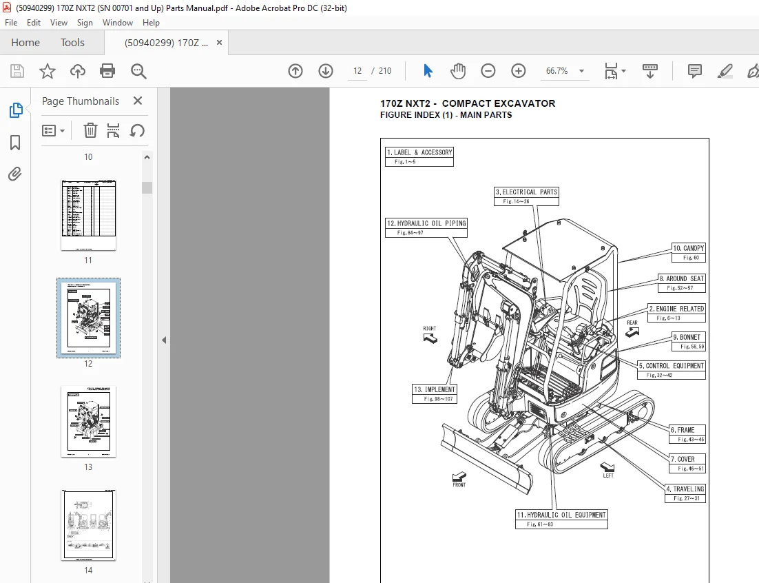
FIGURE INDEX 7
FIG. 2 – LABEL (EXTERIOR) 9
FIG. 3 – LABEL (BONNET INSIDE) 11
FIG. 5 – LABEL (CANOPY) 13
FIG. 6 – SILENCER 15
FIG. 7 – AIR CLEANER 17
FIG. 8 – ACCELERATOR LEVER 19
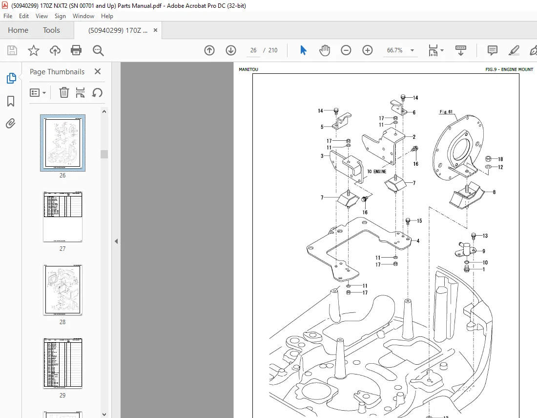
FIG.9 – ENGINE MOUNT 21
FIG. 10 – RADIATOR & MOUNT 23
FIG. 11 – FUEL TANK 25
FIG. 12 – FUEL PIPING 27
FIG. 13 – FUEL FILTER & WATER SEPARATOR (INNER PARTS) 29
FIG. 14 – BATTERY 31
FIG. 15 – ELECTRIC PARTS (ENGINE) 33
FIG. 16 – ELECTRIC PARTS (SEAT MOUNT) 35
FIG. 17 – BATTERY (GROUND CABLE) 37
FIG. 18 – ELECTRICAL PARTS (VALVE PLATE) 39
FIG. 19 – TRAVEL ALARM (SWITCH) 41
FIG. 21 – TRAVEL ALARM 43
FIG. 22 – STARTER SWITCH 45
FIG. 23 – LEVER STAND 47
FIG. 25 – WORK LAMP 49
FIG. 26 – POWER SUPPLY SOCKET 51
FIG. 27 – SPROCKET 53
FIG. 28 – IDLER & ADJUST 55
FIG. 29 – TRACK ROLLER 57
FIG. 30 – SHOE SIDE PLATE 59
FIG. 31 – CRAWLER 61
FIG. 32 – TRAVEL PEDAL 63
FIG. 33 – TRAVEL LEVER 65
FIG. 34 – BLADE LEVER 67
FIG. 35 – VARIABLE LEG LEVER 69
FIG. 36 – SWING PEDAL 71
FIG. 37 – CONTROL EQUIPMENT (LOCK LEVER & STAND) (LEFT) 73
FIG. 38 – CONTROL EQUIPMENT (LOCK LEVER & STAND) (RIGHT) 75
FIG. 39 – CONTROL EQUIPMENT (CONTROL VALVE PLATE) 77
FIG. 40 – CONTROL EQUIPMENT (LOW-HIGH PEDAL) 79
FIG. 41 – CONTROL EQUIPMENT (P.T.O. PEDAL) 81
FIG. 42 – ARM REST 83
FIG. 43 – TRAVEL FRAME 85
FIG. 44 – TURNING FRAME 87
FIG. 45 – TURNING BEARING 89
FIG. 46 – COVER (TRAVEL FRAME) 91
FIG. 47 – COVER (TURNING FRAME) 93
FIG. 49 – COVER (BOOM HOSE) 95
FIG. 51 – SIDE COVER 97
FIG. 52 – COVER (SEAT MOUNT) 99
FIG. 53 – STEP 101
FIG. 54 – INSTRUMENT PANEL 103
FIG. 55 – SEAT 105
FIG. 56 – SEAT MOUNT 107
FIG. 57 – SEAT BELT 109
FIG. 59 – HOOD 111
FIG. 60 – CANOPY 113
FIG. 61 – HYDRAULIC PUMP MOUNT & JOINT 115
FIG. 62 – HYDRAULIC PUMP 117
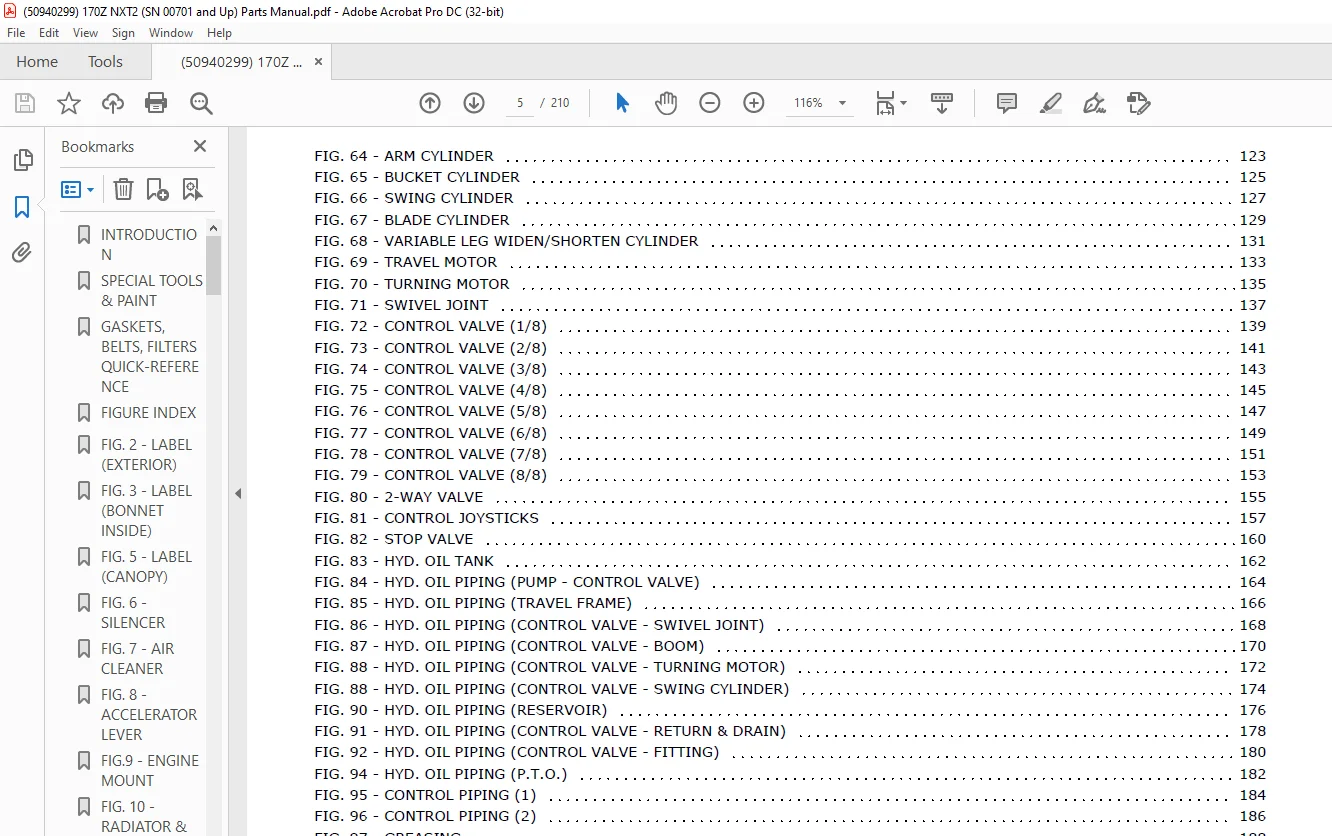
FIG. 63 – BOOM CYLINDER 120
FIG. 64 – ARM CYLINDER 123
FIG. 65 – BUCKET CYLINDER 125
FIG. 66 – SWING CYLINDER 127
FIG. 67 – BLADE CYLINDER 129
FIG. 68 – VARIABLE LEG WIDEN/SHORTEN CYLINDER 131
FIG. 69 – TRAVEL MOTOR 133
FIG. 70 – TURNING MOTOR 135
FIG. 71 – SWIVEL JOINT 137
FIG. 72 – CONTROL VALVE (1/8) 139
FIG. 73 – CONTROL VALVE (2/8) 141
FIG. 74 – CONTROL VALVE (3/8) 143
FIG. 75 – CONTROL VALVE (4/8) 145
FIG. 76 – CONTROL VALVE (5/8) 147
FIG. 77 – CONTROL VALVE (6/8) 149
FIG. 78 – CONTROL VALVE (7/8) 151
FIG. 79 – CONTROL VALVE (8/8) 153
FIG. 80 – 2-WAY VALVE 155
FIG. 81 – CONTROL JOYSTICKS 157
FIG. 82 – STOP VALVE 160
FIG. 83 – HYD. OIL TANK 162
FIG. 84 – HYD. OIL PIPING (PUMP – CONTROL VALVE) 164
FIG. 85 – HYD. OIL PIPING (TRAVEL FRAME) 166
FIG. 86 – HYD. OIL PIPING (CONTROL VALVE – SWIVEL JOINT) 168
FIG. 87 – HYD. OIL PIPING (CONTROL VALVE – BOOM) 170
FIG. 88 – HYD. OIL PIPING (CONTROL VALVE – TURNING MOTOR) 172
FIG. 88 – HYD. OIL PIPING (CONTROL VALVE – SWING CYLINDER) 174
FIG. 90 – HYD. OIL PIPING (RESERVOIR) 176
FIG. 91 – HYD. OIL PIPING (CONTROL VALVE – RETURN & DRAIN) 178
FIG. 92 – HYD. OIL PIPING (CONTROL VALVE – FITTING) 180
FIG. 94 – HYD. OIL PIPING (P.T.O.) 182
FIG. 95 – CONTROL PIPING (1) 184
FIG. 96 – CONTROL PIPING (2) 186
FIG. 97 – GREASING 188
FIG. 98 – BOOM BRACKET 190
FIG. 101 – BOOM 192
FIG. 103 – ARM 194
FIG. 105 – BUCKET ARM & LINK 196
FIG. 107 – BLADE 198
HYDRAULIC QUICK-CONNECT COUPLERS 200
TORQUE SPECIFICATIONS 202
DESCRIPTION:
Mustang Manitou 170Z NXT2 Compact Excavator Parts Manual 50940299 (SN 00701 and up) – PDF DOWNLOAD
INTRODUCTION:
General:
• MANITOU AMERICAS, INC. reserves the right to make changes or improvements in the design or construction of any part of the machine without incurring the obligation to install such changes on any previously delivered machines.
• This parts manual should not be used as a technical data reference; it uses simplified illustrations and does not detail servicing procedures.
• Internal engine components not shown in this manual are contained in a separate engine parts manual. The engine parts manual is contained in the documentation packet shipped with the machine, and is also available separately. Contact your dealer with any documentation requests.
Parts Ordering Information:
IMAGES PREVIEW OF THE MANUAL:
Contact us: [email protected]
https://vimeo.com/805020516
PLEASE NOTE:
- This is the SAME exact manual used by your dealers to fix your vehicle.
- The same can be yours in the next 2-3 mins as you will be directed to the download page immediately after paying for the manual.
- Any queries / doubts regarding your purchase, please feel free to contact [email protected]
S.V