Navistar Electrical Systems Medium, Heavy, Regional and Line Haul Transport Vocational Series Integration Guide Manual
$32.95
Navistar Electrical Systems Medium Heavy Regional and Line Haul Transport Vocational Series Integration Guide Manual – PDF DOWNLOAD
Description
Navistar Electrical Systems Medium, Heavy, Regional and Line Haul Transport Vocational Series Integration Guide Manual – PDF DOWNLOAD
FILE DETAILS:
Navistar Electrical Systems Medium, Heavy, Regional and Line Haul Transport Vocational Series Integration Guide Manual – PDF DOWNLOAD
Language : English
Pages :761
Downloadable : Yes
File Type : PDF
TABLE OF CONTENTS:
Navistar Electrical Systems Medium Heavy Regional and Line Haul Transport Vocational Series Integration Guide Manual – PDF DOWNLOAD
1 Revision Summary Table 11
2 Forward: 11
3 Vehicle Architectures: 14
31 Multiplexing Architecture: 14
32 Vehicle Multiplex Architecture 15
33 Vehicle Power Distribution Architecture: 16
4 Body Control Module (BCM) 17
41 Body Control Module Gen IV: 17
42 Body Control Module “Real-time Clock” Internal Power Source: 18
43 Body Control Module Gen IV Connector Composite: 21
44 Body Controller J1 Connector 1603 I/O & Part Number Detail: 22
45 Body Controller J2 Connector 1604 I/O & Part Number Detail: 23
46 Body Controller J3 Connector 1600 I/O & Part Number Detail: 24
47 Body Controller J4 Connector 1601 I/O & Part Number Detail: 25
48 Body Controller J5 Connector 1602 I/O & Part Number Detail: 26
49 Body Controller J6 Connector 1605 I/O & Part Number Detail: 27
410 Body Controller J7 Connector 1606 I/O & Part Number Detail: 28
5 Multiplex Switch-Packs (Center Panel Mounted) 29
51 Multiplex Switch-Pack Housing: 29
52 Multiplex Switch-Pack Cover 29
53 Multiplex Switch-Pack Storage Bin: 29
54 Multiplex Switch-Pack Actuators, Blanks (plugs) and Indicators: 30
55 Multiplex Switch-Pack Warning Lights: 40
56 Switch Label Applique Sheet #1 (Utility/Wrecker): 42
57 Switch Label Applique Sheet #2 (Fire): 43
58 Switch Label Applique Sheet #3 (Limo/Bus/Propane): 44
59 Switch Label Applique Sheet #4 (Airport Refueler/Concrete Mixer): 45
510 Switch Label Applique Sheet #5 (Plow/Dump): 46
511 Switch Label Applique Sheet #6 (Tanker) 47
512 Switch Label Applique Sheet #7 (Ambulance/Fire): 48
513 Switch Label Applique Sheet #8 (Adv Fire/Ambulance): 49
514 Switch Label Applique Sheet #9 (On/Off/Blank): 50
515 Switch Label Applique Sheet #10 (Miscellaneous): 51
6 Customized Steering Wheel Switches 52
7 Air Solenoid 4-Packs: 57
71 Air Solenoid 4-Pack Wiring: 57
72 Air Solenoid 4-Pack Module Base: 58
73 Air Solenoids: 58
8 Lighting Control Module: 60
81 Lighting Control Module Housing: 60
82 LIGHTING Control Module and Associated Parts: 60
9 Remote Power Module: 60
91 Remote Power Module Composite View 61
92 Remote Power Module CAN Pass-through Connector 62
93 Body Equipment Power Output Connector 63
94 Body Equipment Signal Input Connector 64
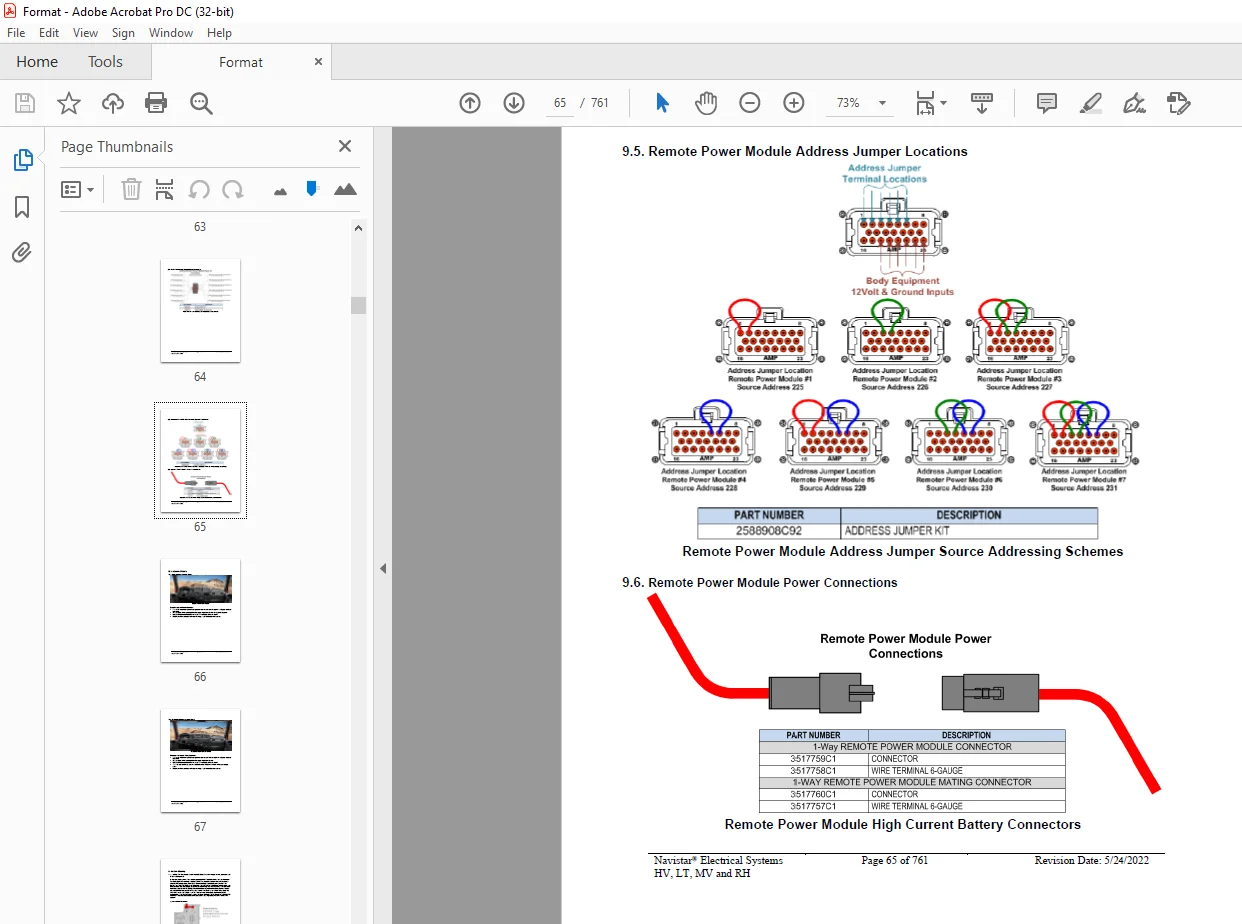
95 Remote Power Module Address Jumper Locations 65
96 Remote Power Module Power Connections 65
10 Instrument Panels 66
101 Base Flat Instrument Panel: 66
102 Premium Flat Instrument Panel: 67
11 Air Conditioning 68
111 16WKB: Air Conditioner (International® Blend Air) with integral heater, defroster and R134-A Refrigerant 68
Navistar® Electrical Systems
HV, LT, MV and RH
Page 3 of 761 Revision Date: 5/24/2022
12 Air Solenoid Features (Normally Open, Closed and Air Horn) 70
121 08XKM: SWITCH, AIR HORN, PASSENGER Fire Truck Application; Switch Located in Instrument Panel (IP) Close to Passenger; Driver Also to Activate Switch at Steering Wheel 70
122 08WGA: SOLENOID, AIR for Customer Use; Provides (1) Normally Closed Pilot Air Source, Approx 4-CFM, Includes Switch in Cab; Air Available Only with Key in “Ignition (IGN)” or “Accessory” Position; Air Will Exhaust with Key in “Off” Position 72
123 08WGB: SOLENOID, AIR for Customer Use; Provides (2) Normally Closed Pilot Air Source, Approx 4-CFM, Includes Switch in Cab; Air Available Only with Key in “IGN” or “Accessory” Position; Air Will Exhaust with Key in “Off” Position 74
124 08WGC: SOLENOID, AIR for Customer Use; Provides (3) Normally Closed Pilot Air Source, Approx 4-CFM, Includes Switch in Cab; Air Available Only with Key in “IGN” or “Accessory” Position; Air Will Exhaust with Key in “Off” Position 76
125 08WGD: SOLENOID, AIR for Customer Use; Provides (4) Normally Closed Pilot Air Source, Approx 4-CFM, Includes Switch in Cab; Air Available Only with Key in “IGN” or “Accessory” Position; Air Will Exhaust with Key in “Off” Position 78
126 08WGP: SOLENOID, AIR for Customer Use; Provides (5) Normally Open Pilot Air Source, Approx 4-CFM, Includes Switch in Cab; Air Exhausted Only with Key in “IGN” or “Accessory” Position; Air Will be Supplied with Key in “Off” Position 80
127 08WGR: SOLENOID, AIR for Customer Use; Provides (6) Normally Open Pilot Air Source, Approx 4-CFM, Includes Switch in Cab; Air Exhausted Only with Key in “IGN” or “Accessory” Position; Air Will be Supplied with Key in “Off” Position 82
128 08WKM: SOLENOID, AIR for Customer Use; Provides (6) Normally Closed Pilot Air Source, Approx 4-CFM, Includes Switch in Cab; Air Available Only with Key in “Ignition” or “Accessory” Position; Air Will Exhaust with key in “Off” Position 84
13 Battery Disconnect Switch Features 86
131 08RLZ: BATTERY DISCONNECT SWITCH {Cole-Hersee 75920-06} 300 Amp, Disconnects Cab Power, Does Not Disconnect Charging Circuits, Locks with Padlock, Battery Box Mounted 86
132 08RMH: BATTERY DISCONNECT SWITCH {Cole-Hersee 75920-06} 300 Amp, Disconnects Charging Circuits, Locks with Padlock, Battery Box Mounted 87
133 08WJV: BATTERY DISCONNECT SWITCH {Joseph Pollak} Locking, Lever Operated, Disconnects Power to PDC, Does Not Disconnect Charging Circuits, Cab Mounted 89
134 08WJW: BATTERY DISCONNECT SWITCH {Joseph Pollak} Key Operated, Disconnects Power to PDC, Does Not Disconnect Charging Circuits, Cab Mounted 92
135 08XHD: BATTERY DISCONNECT SWITCH 300 Amp, Disconnects Charging Circuits, Locks with Padlock, Cab Mounted 94
136 08XHV: BATTERY DISCONNECT SWITCH for Cab Power Disconnect Switch, Disconnects Power to Power Distribution Center (PDC) and Body Builder Through Solenoid, Does Not Disconnect Charging Circuits, Locks with Padlock, Cab Mounted 95
137 08WZP: BATTERY WARNING Green Indicator Mounted on Left Side of Instrument Panel above left side switch panel 97
14 Body Builder Integration Harnesses 99
141 08WZG: JUNCTION BLOCK Stud, 100-Amp Battery Feed, protected by a Fusible Link, Stud to be used for Body Builder Feeds Inside Cab 99
142 08XMB: WIRING (1)TMC RP1226 BEHIND CTR CONSOLE CONNECTOR, DASH, CENTER PANEL Cab Wiring for TMC RP1226 Vehicle Accessory Connector; Includes 14-pin Connector with Switched Power, Battery Power, Ignition Power, Ground & Body 250K Datalink, Connector Located Behind Instrument Panel Center Console 100
143 08XMW: CONNECTOR, OVERHEAD (1)TMC RP1226 CONNECTOR, OVERHEAD Cab Wiring for TMC RP1226 Vehicle Accessory Connector; Includes 14-pin Connector with Switched Power, Battery Power, Ignition Power, Ground & Body 250K Datalink, Connector Located at Overhead Console, for Customer Supplied Cameras 103
144 08XMZ: WIRING (2)TMC RP1226 BEHIND CTR CONSOLECONNECTOR, DASH, CENTER PANEL Cab Wiring for (2) TMC RP1226 Vehicle Accessory Connectors; Includes (2) 14-pin Connectors with Switched Power, Battery Power, Ignition Power, Ground & Body 250K Datalink, Connector Located Behind Instrument Panel Center Console 106
145 08XNA, CENTER PANEL Cab Wiring for (3) TMC RP1226 Vehicle Accessory Connectors; Includes (3) 14-pin Connectors with Switched Power, Battery Power, Ignition Power, Ground & Body 250K Datalink, Connector Located Behind Instrument Panel Center Console 109
146 08XND: CENTER PANEL Cab Wiring for (3) TMC RP1226 Vehicle Accessory Connectors; Includes (1) 14-pin Connectors with Switched Power, Battery Power, Ignition Power, Ground & Body 250K Datalink, Connector Located Behind Auxiliary Gauge Console 112
147 08XNL: CONNECTORS, CHS/BODY INTERFACE Cab Wiring for TMC RP170A 8-pin Conn w/Switched, Battery, Ignition Power & Ground Located on Cab Floor; 31-pin Conn w/Engine, Transmission & Chassis, Data Networks Located on Cab Floor Between Driver & Pass Seats; 14-pin Conn w/Chassis & Body Lightning Signals Located Left Frame Back of Cab 115
Navistar® Electrical Systems
HV, LT, MV and RH
Page 4 of 761 Revision Date: 5/24/2022
148 60ABM: BDY INTG, RPM I/O HARNESS, Includes a Harness with 6 Input Blunt Cut wires and 6 Output Blunt Cut Wires, for use with one RPM 120
149 60ABN: BDY INTG, RPM I/O HARNESS, Includes 2-Harnesses with 6-Input Blunt Cut wires and 6 Output Blunt Cut Wires, for use with two RPMs 121
1410 60ACW: BODY INTG, I/O EXPANSION HARNESS (for Diamond Logic® Builder only) includes a harness with five blunt-cut wires routed on lower left of IP Two GND active inputs and two (05 AMP) relay driver outputs (GND active) are provided 122
15 Body Builder Wiring, for Stop/Turn/Tail Lights/ Though Power: 124
151 08HAA: BODY BUILDER WIRING To EOF, With Stop, Tail, Turn, and Marker Lights Circuits, Ignition (IGN)-Controlled Auxiliary Feed and Ground (GND), Less Trailer Socket 124
152 08HAE: BODY BUILDER WIRING, BOC REAR OF FRAME, includes 7-way sealed connector for tail/amber/backup/accessory power/GND and sealed connectors for combination stop/turn and a 3-way for separate stop/turn lights 132
153 08HAG: ELECTRIC TRAILER BRAKE/LIGHTS Accommodation Package to Rear of Frame (ROF); for Separate Trailer Stop, Tail, Turn, Marker Light Circuits; Includes Electric Trailer Brake Accommodation Package with Cab Connections for Mounting Customer- Installed Electric Brake Unit, Less Trailer Socket 137
154 08HAH: ELECTRIC TRAILER BRAKE/LIGHTS Accommodation Package to Rear of Frame (ROF); for Combined Trailer Stop, Tail, Turn, Marker Light Circuits; Includes Electric Trailer Brake Accommodation Package with Cab Connections for Mounting Customer- Installed Electric Brake Unit, Less Trailer Socket 141
155 08HAT: BODY BUILDER WIRING Includes Wires Installed through the Dash Panel and End in Engine Compartment, In Cab Wire Ends Will Have body controller Input Terminals, Engine Compartment Wire Ends will have Sealed Connectors 144
156 08HAU: BODY BUILDER WIRING INSIDE CAB; Includes Sealed Connectors for Tail/Amber, Turn/Marker/Backup/Accessory, Power/Ground, and Stop/Turn 146
157 08HAV: SPECIAL WIRING HARNESS, BODY with Additional 20″ Length to Rear of Chassis Harness, Coiled at End of Frame Note: Requires electric trailer brake/lights 08HAH 151
158 08NAA: TAIL LIGHT WIRING MODIFIED Includes: Wiring for Standard Left & Right Tail Lights; Separate 80′ of Extra Cable Wiring for Left & Right Body Mounted Tail Lights 151
159 08THG: AUX TRAILER SOCKET 7-Way; With Battery Fed Circuit to Center Pin, with 25-AMP Fuse and Relay Controlled by Switch with Indicator Light on Instrument Panel (IP) Fed from Hot Battery Feed (Not Wired Thru Key Switch) 153
1510 08THH: AUX TRAILER SOCKET 7-Way; With Battery Fed Circuit to Center Pin, with 25 AMP Fuse and Relay Controlled by Switch with Indicator Light Controlled by Accessory Side of Key Switch, Switch Mounted on IP 156
1511 08THU: TRAILER SOCKET 7-Way; With Battery Fed Circuit to Center Pin, with 30-Amp Fuse and Relay Controlled by Switch with Indicator Light on Instrument Panel Fed from Hot Battery Feed, When Parking Brake Is Applied, Not Wired Thru Key Switch 158
1512 08TKK: TRAILER AUXILIARY FEED CIRCUIT for Electric Trailer Brake Accommodation/Air Trailer ABS; With 30-Amp Fuse and Relay, Controlled by Ignition Switch 160
1513 08TME: TRAILER CONNECTION SOCKET 7-Way; Mounted at EOF, Wired for Turn Signals Independent of Stop, Compatible with Trailers That Have Amber or Side Lamps 161
1514 08TMG: TRAILER CONNECTION SOCKET 7-Way; Mounted at EOF, Wired for Turn Signals Combines with Stop, Compatible with Trailers That Use Combined Stop, Tail, Turn Lamps 165
1515 08TMN: TRAILER CONNECTION SOCKET {Phillips STA-DRY} 7-Way; Equipped with ABS Feed, Mounted at BOC and End of Frame Locations 169
1516 08WEB: SPECIAL WIRING HARNESS, BODY for Chassis, with 6-feet of Additional Length to Accommodate Drop Frame Beverage Body Application 172
1517 60AKK: BDY INTG, HEADLIGHTS, WIG WAG High Beam Wig Wag with Park Brake Interlock, Park Brake Disables Wig Wag 173
1518 60AKL: BDY INTG, HEADLIGHTS, WIG WAG High Beam Wig Wag with Park Brake Interlock, Park Brake Disables High Beam Wig Wag, Enables Low Beam Wig Wag 175
16 CB and 2-Way Radio Accommodation Packages 177
161 08RBK: CB ANTENNA (2) {Pana-Pacific} Full Wave; 40′ Length Includes “International®” Name on Top 177
162 08RCB: CB RADIO Accommodation Package; Header Mounted; Feeds from Accessory Side of Ignition Switch; Includes Power Source and Two Antenna Bases with Wiring 178
163 Line Haul Transport (LT 08REA: 2-WAY RADIO Wiring Effects; Wiring with 20-Amp Fuse Protection, Includes Ignition Wire with 5-Amp Fuse, Wire Ends Heat Shrink and 10′ Coil Taped to Base Harness 179
164 08RGA: 2-WAY RADIO Wiring Effects; Wiring with 20-Amp Fuse Protection, Includes Ignition Wire with 5-Amp Fuse, Wire Ends Heat Shrink and Routed to Center of Header Console in Cab 180
17 Engine Speed Control Features and Accommodation Packages 181
Navistar® Electrical Systems
HV, LT, MV and RH
Page 5 of 761 Revision Date: 5/24/2022
171 Datalink Control for Remote Stationary Variable Engine Speed Control: J1939 DATALINK ENGINE CONTROL for Navistar A26 Engines 181
172 12VGV: ACCESSORY WIRING, SPECIAL for Road Speed Wire Coiled Under Instrument Panel for Customer Use, Unconditioned Manual Transmission Output Shaft Speed, Additional Body Builder Signal Conditioning may be Required to Utilize Signal 189
173 12VXT: THROTTLE, HAND CONTROL Engine Speed Control; Electronic, Stationary, Variable Speed; Mounted on Steering Wheel 191
174 12VXU: THROTTLE, HAND CONTROL Engine Speed Control for PTO; Electronic, Stationary Pre-Set, Two Speed Settings; Mounted on Steering Wheel 192
175 12VXV: THROTTLE, HAND CONTROL Engine Speed Control for PTO; Electronic, Mobile (Range 2 to 20-MPH), Variable Speed; Mounted on Steering Wheel 193
176 12VYL: ACCESSORY WIRING, SPECIAL for Road Speed Wire Coiled Under Instrument Panel for Customer Use 194
177 12VGA Pre 2022 Model Year A26: ENGINE CONTROL, REMOTE MOUNTED for PTO, for A26 Engines 196
1771 12VGA Preset Set Speed – Wiring Diagram: 198
1772 12VGA Preset Resume Speed – Wiring Diagram: 199
1773 12VGA Preset Set Resume Speed – Wiring Diagram: 200
1774 12VGA Variable Switch Control – Wiring Diagram: 201
1775 12VGA Variable Pedal Control – Wiring Diagram: 202
1776 12VGA Transfer Case Speed Disable – Wiring Diagram: 203
1777 12VGA Aux Tachometer Output – Wiring Diagram: 204
1778 12VGA Aux Speedometer Output – Wiring Diagram: 205
1779 12VGA Engine Waring Lamp – Wiring Diagram: 206
178 12VGA Post 2021 Model Year A26: ENGINE CONTROL, REMOTE MOUNTED for PTO, for A26 Engines 208
1781 12VGA Preset Set Speed – Wiring Diagram: 209
1782 12VGA Preset Resume Speed – Wiring Diagram: 210
1783 12VGA Preset Set Resume Speed – Wiring Diagram: 210
1784 12VGA Variable Switch Control – Wiring Diagram: 211
1785 12VGA Variable Pedal Control – Wiring Diagram: 212
1786 12VGA Transfer Case Speed Disable – Wiring Diagram: 213
1787 12VGA Aux Tachometer Output – Wiring Diagram: 214
1788 12VGA Aux Speedometer Output – Wiring Diagram: 214
1789 12VGA Engine Waring Lamp – Wiring Diagram: 215
179 12XAT: ENGINE CONTROL, REMOTE MOUNTED Provision for; Includes Wiring for Body Builder Installation of PTO Controls; with Ignition Switch Control for Cummins ISB/B67 or ISL/L9 Engines 217
1791 12XAT: SEVERE VOCATIONAL SERIES – Wiring Diagrams: 220
17911 12XAT Preset Set Speed – Wiring Diagram (Severe Vocational Series): 220
17912 12XAT: Preset Resume Speed – Wiring Diagram (Severe Vocational Series): 221
17914 12XAT: Preset Set Resume Speed – Wiring Diagram (Severe Vocational Series): 222
17915 12XAT: Variable Pedal Control – Wiring Diagram (Severe Vocational Series): 223
17916 12XAT: Auxiliary Tachometer – Wiring Diagram (Severe Vocational Series): 224
17917 12XAT: Engine or Vehicle Speed Switch – Wiring Diagram (Severe Vocational Series): 225
17918 12XAT: Rear Axle Ratio Switch – Wiring Diagram (Severe Vocational Series): 226
1792 12XAT: MEDIUM VOCATIONAL SERIES – Wiring Diagrams: 228
17924 12XAT: Preset Set Speed – Wiring Diagram (Medium Vocational Series): 229
17925 12XAT: Preset Resume Speed – Wiring Diagram (Medium Vocational Series): 230
17926 12XAT: Preset Set Resume Speed – Wiring Diagram (Medium Vocational Series): 231
17927 12XAT: Variable Set Resume Speed – Wiring Diagram (Medium Vocational Series): 232
17928 12XAT: Variable Pedal Control – Wiring Diagram (Medium Vocational Series): 233
17929 12XAT: Auxiliary Tachometer – Wiring Diagram (Medium Vocational Series): 234
1793 12XAT: MEDIUM VOCATIONAL SERIES – Wiring Diagrams: 236
1710 12XBM: ENGINE CONTROL, REMOTE MOUNTED Provision for; Includes Wiring for Body Builder Installation of PTO Controls and Starter Lockout; with Ignition Switch Control for Cummins B67 and L9 Engines 238
17101 12XBM: Severe and Medium Vocational Series Vehicle Wiring Diagrams: 240
171011 12XBM: Preset Set Speed – Wiring Diagram: 240
171012 12XBM: Preset Resume Speed – Wiring Diagram: 241
171013 12XBM: Preset Set Resume – Wiring Diagram: 242
171014 12XBM: Variable Set Resume – Wiring Diagram: 243
171015 12XBM: Variable Pedal Control – Wiring Diagram: 244
171016 12XBM: Auxiliary Tachometer – Wiring Diagram: 245
171017 12XBM: Engine or Vehicle Speed Switch – Wiring Diagram: 246
171018 12XBM: Accelerator / Brake Override or Rear Axle Ratio Switch – Wiring Diagram: 247
171019 12XBM: Starter Lockout – Wiring Diagram: 248
1711 60AJA: BDY INTG, THROTTLE CONTROL Accommodation for Single Customer-Mounted External Engine Speed Control Switch, Programmable Mode for Various Switch Actions and
Navistar® Electrical Systems
HV, LT, MV and RH
Page 6 of 761 Revision Date: 5/24/2022
Engine Speed Control Option; Useable Only While Vehicle is Stopped, and the Park Brake is Applied (requires one Remote Power Module (RPM) input) 250
1712 60AJE: BDY INTG, THROTTLE CONTROL Accommodation for On Demand Engine Speed for Single Customer-Mounted Pressure Switch, Programmable Mode for Various Switch Actions, Useable Only While Vehicle is Stopped, and the Park Brake is Applied (requires one RPM input) 254
1713 60AJG: BDY INTG, THROTTLE CONTROL Accommodation for Single Customer-Mounted External Engine Speed Control Switch, for Utility Applications, Programmable Mode for Various Switch Actions and Engine Speed Control Option, Only with Vehicle Stopped and Park Brake is Applied (requires one RPM input) 258
1714 60AJH: BDY INTG, THROTTLE CONTROL for Dual Function Input, for Utility Applications, Remote Throttle Control When Engine is Running, and Activating Output for Emergency Power When the Engine is Not Engaged; Useable Only When Vehicle is Stopped, and Park Brake is Applied (requires one RPM input and output) 262
1715 60AJJ: BDY INTG, THROTTLE CONTROL Accommodation for Single Customer-Mounted Momentary Switch, for Refuse Applications, Programmable Mode Various Switch Actions, Useable Only While Vehicle is Stopped, and the Park Brake is Applied (requires one RPM input) 266
18 Fog, Plow and Guide Post Accommodation Packages 270
181 8585: TOGGLE SWITCH, AUXILIARY and Wiring; For Driving Lights or Fog Lights Mounted by Customer 270
182 08THJ: AUXILIARY HARNESS 30’ for Auxiliary Front Headlights and Turn Signals for Front Plow Applications 273
183 08THV: DISCONNECT, FRONT HARNESS for Guide Post Lights; Connectors Located at Headlight Connection, for Customer Installation 275
184 08TNP: AUXILIARY HARNESS 50’ for Auxiliary Front Headlights and Turn Signals for Front Plow Applications 276
185 08WLM: FOG LIGHTS {Peterson} Amber, Halogen, Rectangular 279
186 08WLN: FOG LIGHTS {Peterson} Clear, Halogen, Rectangular 282
187 08WPL: FOG LIGHTS (2) Amber, Oval, With H355W Halogen Bulb 285
188 08WPM: FOG LIGHTS (2) Clear, Oval, With H355W Halogen Bulb 288
189 08XJG: FOG LIGHTS (2) Clear, Lens, Halogen, Rectangular, with White Light Source 291
1810 08XJH: FOG LIGHTS (2) Clear, Lens, LED, Rectangular, with White Light Source 294
1811 08XJJ: FOG LIGHTS (2) Selective Yellow, LED 297
19 Disable ABS/ATC for Rail Applications 300
191 Disabling ABS/ATC by Removing Power to Module 300
192 Disable ABS/ATC with Bendix ABS inputs: 301
20 Lift Axles 302
201 Lift Axle Control (Using Conventional Air Solenoid Module): 302
202 Lift Axle Electronic Gauges: 307
21 Gauges and Fault Code Display 310
211 16HGG: GAUGE, OIL TEMP, ENGINE 310
212 16HGH: OIL TEMP GAUGE FOR AUTOMATIC TRANS 313
213 16HGJ: GAUGE, OIL TEMP, MANUAL TRANSMISSION 316
214 16HGL: GAUGE, OIL TEMP, REAR AXLE 319
215 16HGN: GAUGE, AIR APPLICATION 323
216 16HHT: GAUGE, Ammeter 150-Ampere (AMP) 326
217 16HKT: IP CLUSTER DISPLAY DIAGNOSTICS — Display on board diagnostics of fault codes in gauge cluster 328
218 16HLR: VIRTUAL GA, OIL TEMP, Air Application Requires Premium Cluster 329
219 16HLS: VIRTUAL GA, OIL TEMP, REAR AXLE Requires Premium Cluster 329
2110 16HLU: VIRTUAL GA, OIL TEMP, AUTO XMSN for Allison Transmission, Requires Premium Cluster 333
2111 16HLV: VIRTUAL GA, OIL TEMP, MANL XMSN for Manual Transmission, Requires Premium Cluster 335
2112 16HLW: VIRTUAL GAUGE, OIL TEMP, ENG Requires Premium Cluster 339
22 In Cab Battery Feed Power Source 341
221 8518: CIGAR LIGHTER Includes Ash Cup 341
222 8718: POWER SOURCE Cigar Type Receptacle without Plug and Cord 342
223 08WCK POWER SOURCE, TERMINAL TYPE 2-Post 343
224 08XHR POWER SOURCE, ADDITIONAL Auxiliary Power Outlet (APO) & USB Port, Located in the Instrument Panel 344
Navistar® Electrical Systems
HV, LT, MV and RH
Page 7 of 761 Revision Date: 5/24/2022
225 08XKR: POWER SOURCE, Two Auxiliary Power Outlets (APO) and Two USB Ports, Located in the Instrument Panel 345
23 Indicator Lights and Alarms 347
231 60AJC: BDY INTG, INDICATOR LIGHTS (2) One for Gate Open and One for Rear Alert, Includes Audible Alarm, Programmable Mode for Various Switch Action (requires 2 Remote Power Module (RPM) inputs) 347
232 60AJD: BDY INTG, INDICATOR LIGHTS (2) One for Boom Out of Stow, One for Outriggers Deployed, Includes Audible Alarm and Interlock to Parking Brake, Programmable Mode for Various Switch Actions (requires 2 RPM inputs) 351
233 60AJK: INDICATOR LIGHTS (2), One for Body Up, One for Gate Open, Includes Audible Alarm, Programmable Mode for Various Switch Actions (Requires 2-RPM Inputs) 354
234 60AKY: BDY INTG, DASH IND LT TRICOLOR (1) for Optional Usage Customer to Program 358
235 60AKZ: BDY INTG, DASH IND LT TRICOLOR (2) for Optional Usage Customer to Program 359
236 60ALA: BDY INTG, DASH IND LT TRICOLOR (3) for Optional Usage Customer to Program 361
237 60ALB: BDY INTG, DASH IND LT TRICOLOR (4) for Optional Usage Customer to Program 363
238 60ALC: BDY INTG, DASH IND LT TRICOLOR (5) for Optional Usage Customer to Program 364
239 60ALD: BDY INTG, DASH IND LT TRICOLOR (6) for Optional Usage Customer to Program 366
2310 60ALE: BDY INTG, DASH IND LT TRICOLOR (7) for Optional Usage Customer to Program 368
2311 60ALG: BDY INTG, DASH IND LT TRICOLOR (8) for Optional Usage Customer to Program 369
2312 60ALH: BDY INTG, DASH IND LT TRICOLOR (9) for Optional Usage Customer to Program 371
2313 60ALJ: BDY INTG, DASH IND LT TRICOLOR (10) for Optional Usage Customer to Program 373
2314 60ALK: BDY INTG, DASH IND LT TRICOLOR (11) for Optional Usage Customer to Program 375
2315 60ALL: BDY INTG, DASH IND LT TRICOLOR (12) for Optional Usage Customer to Program 377
24 Liftgate Accommodation Packages 379 241 08VBA: POWER SOURCE, SPECIAL for Customer Installed Lift Gate; 200 Amp Max, Includes 00ga Power Cable to End of Frame, Optional Power (PDM) for Power Source, Latched Switch on Instrument Panel, with a Time Out Feature, Battery Discharge Protection, Controlling a Mag Switch Which Provides Power 379
242 08TWG: POWER SOURCE, SPECIAL {Erich Jaeger} Socket, Single Terminal, for Power Lift Gate Feed, Battery Feed Thru 150 Amp Circuit Breaker, To Operate Lift Gate On Trailer, Includes a 15’ Power Cable Coiled In Cab 381
243 08TWJ: POWER SOURCE, SPECIAL {Erich Jaeger} Socket, Dual Pole Terminal, for Power Lift Gate Feed, Battery Feed Thru 150 Amp Circuit Breaker, To Operate Lift Gate On Trailer, Includes a 15’ Coiled Dual Pole Power Cable Shipped in Cab 382
244 08WCM: POWER SOURCE, Special Socket; Single Terminal, for Power Lift Gate Feed, Battery Feed Thru 150-Amp Circuit Breaker, To Operate Lift Gate on Trailer, includes a 15-foot Power Cable Coiled in Cab 383
245 08WJA: POWER SOURCE, SPECIAL for Customer Installed Lift Gate; 200 Amp Max, Includes 2ga Power Cable to End of Frame, Latched Switch on Instrument Panel, with a Time Out Feature, Battery Discharge Protection, Controlling a Mag Switch Which Provides Power 385
246 08WJH: POWER SOURCE, SPECIAL – Special Socket; Dual Pole Terminal, for Power Lift Gate Feed, Battery Feed Thru 150-Amp Circuit Breaker to Operate Lift Gate on Trailer 386
247 08WKP: POWER SOURCE, SPECIAL {Phillips} Socket, Dual Pole Terminal, for Power Lift Gate Feed, Battery Feed Thru 150 Amp Circuit Breaker, To Operate Lift Gate On Trailer, Includes a 15’ Coiled Dual Pole Power Cable Shipped in Cab 388
248 08WSS: POWER SOURCE, SPECIAL {Phillips} Socket, Dual Pole Terminal, for Power Lift Gate Feed, Battery Feed Thru 150 Amp Circuit Breaker, To Operate Lift Gate On Trailer, includes a Phillips Weather-Tite M2 12’ Straight Dual Pole Power Cable Shipped in Cab 389
25 Power Features using Remote Power Modules 391
251 60ACE: BDY INTG, SWITCH DUAL OUTPUT 2-Position Latched Rocker, Backlit, with “ON” Indicator Mounted on Dash, for 1; Auxiliary Load 40-AMP Maximum; Power Available Only in “Ignition (IGN)” or “Accessory” Position; Controls Two Remote Power Modules (RPMs) (requires two RPM outputs) 391
252 60ACG: BDY INTG, SWITCH, INTERLOCKED 2-Position Latched Rocker, Backlit, with “ON” Indicator Mounted on Dash for 1; Auxiliary Load 20-Ampere (AMP) Maximum; Output will disengage when Vehicle Exceeds 30-MPH, Programmable; Power Available Only in “Ignition (IGN)” or “Accessory” Position (requires one Remote Power Module (RPM) output) 394
253 60ACH: BDY INTG, SWITCH, INTERLOCKED (2) 2-Position Latched Rockers, Backlit, with “ON” Indicator Mtd on Dash, for 2; Auxiliary Load each 20-AMP Maximum; Outputs will Disengage when Vehicle Exceeds 30-MPH, Programmable; Power Available Only in “IGN” or “Accessory” Position (requires two RPM outputs) 398
254 60ACS: BDY INTG, SWITCH MOMNTRY 3POS Rocker, Backlit, with “ON” Indicator Mounted on Dash, Latching Software, for 1 Auxiliary Load 20-amp Maximum; Power Available Only in “Ignition” or “Accessory” Position, Output Also Controlled by a Customer Remote Mounted Switch (requires 1 Remote Power Module input and 1output) 405
Navistar® Electrical Systems
HV, LT, MV and RH
Page 8 of 761 Revision Date: 5/24/2022
255 60ACT: BDY INTG, SWITCH MOMNTRY 3POS Rocker, Backlit, with “ON” Indicator Mounted on Dash, Latching Software, for 2; Auxiliary Load 20-AMP Maximum; Power Available Only in “IGN” or “Accessory” Position, Output Also Controlled by a Customer Remote-Mounted Switch (requires two RPM inputs and two outputs) 408
256 60ACU: BDY INTG, SWITCH MOMNTRY 3-POS (3) Rocker, Backlit, with “ON” Indicator Mounted on Dash, Latching Software, for 3; Auxiliary Load 20-AMP Maximum; Power Available Only in “IGN” or “Accessory” Position, Output Also Controlled by a Customer Remote-Mounted Switch (requires three RPM inputs and three outputs) 412
257 60AJL: BDY INTG, REMOTE POWER MODULE Mounted Inside Cab; Up to 6-Outputs & 6 Inputs, Max 20-AMP per Channel, Max 80-AMP Total; (Includes 1-Switch Pack with Latched Switches) 416
258 60AJM: BDY INTG, REMOTE POWER MODULE (2) Mounted Inside Cab; Up to 6-Outputs & 6-Inputs each, Max 20-AMP per Channel, Max 80-AMP Total; (Includes Switch Packs with Latched Switches) 421
26 Power Window, Locks, Remote Keyless Entry 428
261 16VCN: KEYLESS ENTRY SYSTEM REMOTE with Panic and Auxiliary Work Light Function, Includes One Key Fob (Transmitter) 428
262 16VCP: KEYLESS ENTRY SYSTEM REMOTE with Panic and Horn Beep Lock Confirmation, with Auxiliary Button for Work Light, Includes One Key Fob (Transmitter) 432
263 16WJU: WINDOW, POWER (2-Door) and Power Locks, Left and Right Doors 436
264 16WJV: WINDOW, POWER (4-Door) and Power Door Locks, Front and Rear Doors, Left and Right 439
265 16WKZ: KEYLESS ENTRY SYSTEM REMOTE with Panic and Auxiliary Buttons, Includes One Key Fob (Transmitter) 441
27 Productivity Features 444
271 08THN: TURN SIGNAL SWITCH with Hazard Flasher Overrides Brake, to be done With Programming System Controller 444
272 08WXB: HEADLIGHT WARNING BUZZER Sounds When Head Light Switch is on and Ignition Switch is in “Off” Position 445
273 08WXD: ALARM, PARKING BRAKE Electric Horn Sounds in Repetitive Manner when Vehicle Park Brake is “NOT” Set, With Ignition (IGN) “OFF” and any Door Open 446
274 16HCK: SEATBELT WARNING PREWIRE for 1 to 3 Belts 448
275 16HCL: SEATBELT WARNING PREWIRE for 4 to 6-Belts 449
28 PTO (Power Take OFF) and PTO Hour Meter 450
281 13WDN: PTO CONTROL, DASH MOUNTED for Customer Provided PTO; Includes 2-Independent Illuminated Switches, 2-Electric/Air Solenoids, Piping and Wiring 450
282 13XAA: PTO CONTROL, DASH MOUNTED for Customer Provided PTO; Includes Switch, Electric/Air Solenoid, Piping and Wiring 471
283 16WLM: HOUR METER, PTO for Customer Provided PTO; Indicator Light and Hour meter in Gauge Cluster Includes Return Wire for PTO Feedback Switch 479
284 60ABA: BDY INTG, PTO ACCOMMODATION for Monitoring Cable Shift Engaged PTO, With Indicator Light and Audible Alarm in Gauge Cluster (requires one Remote Power Module (RPM) input) 483
285 60ABB: BDY INTG, PTO ACCOMMODATION for Muncie Lectra-Shift PTO Engagement and Disengagement, With Switch Mounted on Dash; Includes Indicator Light and Audible Alarm in Gauge Cluster (requires one RPM input and one output) 487
286 60ABE: BDY INTG, PTO ACCOMMODATION for Electric over Hydraulic PTO, With Switch Mounted on Dash, Includes Audible Alarm and Indicator Light in Gauge Cluster (Requires one RPM input and one output) This feature does Not Include Solenoids 497
287 60ABK: BDY INTG, PTO ACCOMMODATION Accommodation for Electric over Air, Non-Clutched PTO Engagement and Disengagement does not Include Air Solenoid, With Switch Mounted on Dash, Includes Audible Alarm and Indicator Light in Gauge Cluster (requires one RPM input and one output) 507
288 60ABL: BDY INTG, PTO ACCOMMODATION Accommodation for Electric over Air, Clutched PTO Engagement and Disengagement, does not Include Air Solenoid, With Switch Mounted on Dash, Includes Audible Alarm and Indicator Light in Gauge Cluster (requires one RPM input and one output) 517
289 60ABR: BDY INTG, PTO ACCOMMODATION for Electric over Air, Non-Clutched PTO Engagement and Disengagement, does not Include Air Solenoid, with 2-Latched Switches Mounted on Dash, Includes Audible Alarm and Indicator Light in Gauge Cluster (requires 2 Remote Input Power Module Inputs & 2 Outputs) 527
2810 60AKG: BDY INTG, PTO ACCOMMODATION for (3) Latched Rocker Switches, (1) PTO Switch, (2) Generic Switches to Control (3) 30-amp relays, with Programmable Interlocks, for Body Builder Hook up in the Engine Compartment Left Side, Recommended for Automatic Transmissions 542
Navistar® Electrical Systems
HV, LT, MV and RH
Page 9 of 761 Revision Date: 5/24/2022
29 Remote Power Modules 554
291 08SAJ: SWITCH, BODY CIRCUITS, MID for Body Builder; 12-Momentary Switches in IP, With Two Power Modules with Six Channels, 20-AMP Max per Channel, 80-AMP Max Output, Switch Control Power Modules through Multiplex Wiring, Mounted on Battery Box, BOC 554
292 08VZR: SWITCH, BODY CIRCUITS, MID for Bodybuilder, 6-Switches in Instrument Panel; One Power Module with 6 Channels, 20-Amp Max Per Channel, 80 Amp Max Output, Switches Control Power Module Through Multiplex Wiring, Mounted in Cab Behind Driver Seat 561
293 08VZS: SWITCH, BODY CIRCUITS, MID for Bodybuilder, 12-Switches in Instrument Panel; Two Power Modules with 6 Channels, 20-Amp Max Per Channel, 80-Amp Max Output, Switches Control Power Module Through Multiplex Wiring, Mounted in Cab Behind Driver Seat 566
294 08WSK: SWITCH, BODY CIRCUITS, REAR for Body Builder; With Six Momentary Switches in Instrument Panel (IP); One Power Module, With Six Channels, 20-Ampere (AMP) per Channel and 80 AMP Max Output, Switches Control the Power Modules through Multiplex Wiring, Mounted at Rear on Frame 573
295 08WSM: SWITCH, BODY CIRCUITS, MID for Body Builder, With Six Momentary Switches in IP; One Power Module with Six Channel, 20-AMP Max per Channel and 80 AMP Max Output, Switches Control the Power Module through Multiplex Wiring, Mounted Battery Box, Back of Cab (BOC) 578
296 60AAA: BDY INTG, RPM Mounted Under Cab; Up to Six Outputs and Six Inputs, Max 20-AMP per Channel, Max 80-AMP Total (Includes One Switch Pack with Latched Switches) Mounted on Battery Box, BOC 583
297 60AAB: BDY INTG, RPM (2) Mounted Under Cab; Up to Six Outputs and Six Inputs Each, Max 20 AMP per Channel, Max 80 AMP Total per Power Module (Includes Switch Packs with Latched Switches) Mounted on Battery Box, BOC 589
298 60AAD: BDY INTG, RPM (2) {SPECIAL} Mounted Under Cab or on Battery Box; Max 20-AMP per Channel, Max 80-AMP Total per Power Module; Includes One Module with Switch Pack Containing Six Latched Switches and One Module with Hardware Only 596
299 60AAG: BDY INTG, RPM Mounted Inside Cab behind Driver Seat; Max 20-AMP per Channel, Max 80-AMP Total; Includes One Module with Switch Pack Containing Latched Switches 602
2910 60AAH: BDY INTG, RPM (2) Mounted Inside Cab behind Driver Seat; Max 20-AMP per Channel, Max 80-AMP Total; Includes Two Modules with 2-Switch Packs Containing Latched Switches 608
2911 60AAJ: BDY INTG, RPM (3) Mounted Inside Cab behind Driver Seat; Max 20-AMP per Channel, Max 80-AMP Total; Includes Three Modules with 3-Switch Packs Containing Latched Switches 615
2912 60AAK: BDY INTG, RPM (2) {SPECIAL} Mounted Inside Cab behind Driver Seat; Max 20-AMP per Channel, Max 80-AMP Total; Includes One Module with Switch Pack Containing Six Latched Switches and One Module with Hardware Only 624
2913 60AAL: BDY INTG, RPM {SPECIAL} Mounted Inside Cab behind Driver Seat; Max 20-AMP per Channel, Max 80-AMP Total; Includes Three Modules with Hardware Only 630
2914 60AAM: BDY INTG, RPM AUX Mounted on the Driver’s Side Frame Rail at Rear of Frame; Up to 6-Outputs and 6-Inputs, Max 20-AMP per Channel, Max 80-AMP Total 632
2915 60AAN: BDY INTG, RPM AUX Mounted Back of Cab; Up to 6-Outputs and Inputs, Max 20-AMP per Channel, Max 80-AMP Total 634
30 Remote Start/Stop Features 636
301 60ABCM: BDY INTG, REMOTE START/STOP to Start and Stop Vehicle Engine 636
302 60ABD: BDY INTG, REMOTE START/STOP To Start and Stop Vehicle Engine, Will Start Emergency Pump Motor, Programmable Time Intervals 640
31 Secondary Road Speed Limit 644
311 Datalink Control for Secondary Road Speed Limit Control: J1939 DATALINK ENGINE CONTROL for Navistar A26 Engines Limited to vehicles with Allison transmissions 644
32 Standard electrical Offerings 647
321 08WRB: HEADLIGHTS ON W/WIPERS Headlights Will Automatically Turn on if Windshield Wipers are turned on There are two functions, Lights on With Wipers (LOWW) and Day Time Running Lights (DTRL), available with this sales code 647
33 Theft Deterrent 648
331 60ACX: BODY INTG, THEFT DETERRENT SYS Includes one (1) Switch Pack of Six Switches 648
34 Eaton® Transmission Spare Input/Output (I/O) and sales codes 651
341 Eaton® Ultrashift™ transmission PTO Feedback 651
342 13WEW: WIRING, TRANSMISSION Installed Wiring and Connector for Transmission/PTO Controls, for Eaton® Endurant™ Transmission 652
343 13WEP: WIRING, TRANS, BODY BUILDER Installed Wiring and Connector for Transmission/PTO Controls, for Eaton® Procision™ Transmission 654
Navistar® Electrical Systems
HV, LT, MV and RH
Page 10 of 761 Revision Date: 5/24/2022
35 Allison 1000 and 2000 Transmission Spare Input/Output (I/O) and Sales Codes 656
351 13WDH Description: WIRING, TRANS BODY BUILDER Installed Wiring for Transmission/PTO Controls, for Allison 2000, 2100, 2200, 2400, 2500 Series Transmission Only 656
352 13XAC: ALLISON SPARE INPUT/OUTPUT for Rugged Duty Series (RDS), General Purpose Trucks, Package Number 354, Modified for Single Input Auto Neutral Feature Applicability to Vehicle Platforms: 659
36 Allison 3000 and 4000 Transmission Auto Neutral 661
361 13AAZ: AUTOMATIC NEUTRAL Allison 3000 & 4000 Series Transmission Shifts to Neutral When Parking Brake is Engaged 661
362 13WEH: AUTOMATIC NEUTRAL Allison WT Transmission Shifts to Neutral When Parking Brake is Engaged and Remains in Neutral When Parking Brake is Disengaged, without On/Off Switch 661
363 13WUA: ALLISON NEUTRAL Allison WT Transmission Shifts to Neutral When Parking Brake is Engaged and Remains on Neutral When Park Brake is Disengaged 664
37 Allison 3000 and 4000 Transmission Spare Input/Output (I/O) and Sales Codes 666
371 13WUB: ALLISON SPARE INPUT/OUTPUT for Highway Series (HS); General Purpose Trucks Package number 223 670
372 13WUC: ALLISON SPARE INPUT/OUTPUT for Rugged Duty Series (RDS); General Purpose Trucks, Construction 673
373 13WUD: ALLISON SPARE INPUT/OUTPUT for Emergency Vehicle Series (EVS); Rescue, Ambulance 676
374 13WUE: ALLISON SPARE INPUT/OUTPUT for Emergency Vehicle Series (EVS); Fire/Pumper, Tank, Aerial/Ladder 679
375 13WUH: ALLISON SPARE INPUT/OUTPUT for Rugged Duty Series (RDS); Airport Refueler, Sewer Evac 682
376 13WUJ: ALLISON SPARE INPUT/OUTPUT for Rugged Duty Series (RDS); Front Loaders, Rear Loaders, Recycling/Packer Trucks 685
377 13WUK: ALLISON SPARE INPUT/OUTPUT for Rugged Duty Series (RDS); Side Loaders 688
378 13WUL: ALLISON SPARE INPUT/OUTPUT for Rugged Duty Series (RDS); Street Sweeper 691
379 13WUN: ALLISON SPARE INPUT/OUTPUT for Motorhome Series (MH), Package Number 226 694
3710 13WUS: ALLISON SPARE INPUT/OUTPUT for Rugged Duty Series (RDS); General Purpose Trucks Modified for Single Input Auto Neutral 697
3711 13WUT: ALLISON SPARE INPUT/OUTPUT for Emergency Vehicle Series (EVS); Without Split Shaft PTO 700
3712 13WUV: ALLISON SPARE INPUT/OUTPUT for Highway Series (HS); General Purpose Trucks Modified for Single Input Auto Neutral 703
3713 13WUZ: ALLISON SPARE INPUT/OUTPUT for Emergency Vehicle Series (EVS), Fire/Pumper, Tank, Aerial/Ladder, Package Number 198, Includes J1939 Based Auto Neutral 706
3714 13WVA: ALLISON SPARE INPUT/OUTPUT for Emergency Vehicle Series (EVS), 303/360 Includes J1939 Based Auto Neutral; Fire/Pumper, Tank, Aerial/Ladder 709
3715 13WVB: ALLISON SPARE INPUT/OUTPUT for Emergency Vehicle Series (EVS), Rescue, Ambulance, Package Number 170, Includes J1939 Based Auto Neutral 711
38 Work light and Outside Cab Power Features 715
381 08TMH: SWITCH, AUXILIARY Accessory Control; for Wiring in Roof, With Maximum of 20 AMP Load with Switches in the Instrument Panel 715 382 08XBM: TOGGLE SWITCH, AUXILIARY (1) with One 30-Amp Circuit Breaker 716 383 08XBN: TOGGLE SWITCH, AUXILIARY (2) with Two 30-Amp Circuit Breakers 717
384 08WAA: WORK LIGHT (LED); Pedestal Mounted with Switch on Instrument Panel (Truck Lite 81 Series) 718
385 08WJZ: WORKLIGHT ON W/BACKUP Work Lights will Activate when Vehicle is in Reverse 722
386 08WEX: AUXILIARY HARNESS for Auxiliary Power Source; 30-Amp, Key Switched, 2-Pin Connector, Located on Floor Between Seats 724
387 08WLL: WORK LIGHT; Pedestal Mounted with Switch on Instrument Panel (Truck Lite 81 Series) 725
388 08WMA: SWITCH, TOGGLE, FOR WORK LIGHT Lighted; on Instrument Panel and Wiring Effects for Customer Furnished Back of Cab Light 729
389 08WXN: WORK LIGHT (2) (Grote) 60 Series, Mounted Under Hood One Each Side 733
3810 08XBK: SWITCH, AUXILIARY Switch 40-AMP Circuit for Customer Use; Includes Wiring Connection in the engine compartment near the mega-fuse 736
39 Appendix – General Electrical Section: 738
391 “Red Gel Coat” Removal from Starter Studs and Electrical Connections 738
392 Color Code System for International® Truck Wiring: 745
393 Recommended Circuit Protection: 745
394 Electrical Components Commonly Used by Equipment Installers: 746
395 Wire Splicing and Termination – Standard Terminals and Splices: 747
IMAGES PREVIEW OF THE MANUAL:
![]()
![]()
![]()
S.M 07/24