Neptune-C2 MPW2400 Service Manual PDF B286 Wide Format Copier Printer PDF
Original price was: $75.00.$20.95Current price is: $20.95.
Official Neptune-C2 service manual for MPW2400 wide format copier/printer (Machine Code B286, March 2007). This comprehensive 569-page technical manual covers installation procedures, mechanical component layouts, drum assembly service, scanner mechanisms, image processing, troubleshooting with SC codes, jam clearance, board diagnostics, SP mode adjustments, CIS/LPH calibration, replacement procedures, wiring diagrams, and complete service information for qualified technicians servicing Neptune-C2 digital imaging systems.
Description
Neptune-C2 MPW2400 Service Manual PDF B286 Wide Format Copier Printer – PDF DOWNLOAD
DESCRIPTION
This is the official Neptune-C2 Service Manual (Machine Code B286, March 2007) for the MPW2400 wide format digital copier/printer system. This comprehensive 569-page technical manual provides complete service, maintenance, troubleshooting, and repair information for qualified technicians to install, calibrate, diagnose, and maintain these advanced wide format imaging systems used in engineering offices, architectural firms, reprographic centers, and professional printing environments worldwide.
Product Overview
Neptune-C2 (MPW2400) Wide Format System:
The Neptune-C2 represents an advanced wide format digital copier and printer designed for high-volume reproduction of engineering drawings, architectural plans, construction documents, and large format graphics. This sophisticated system combines high-speed scanning, precise electrophotographic imaging, advanced image processing, and versatile paper handling options including roll feed capability for continuous production in demanding professional environments.
Key Applications:
- Engineering document reproduction
- Architectural drawing copying
- Construction plan printing
- CAD/CAM output
- GIS mapping reproduction
- Blueprint copying
- Technical documentation
- Large format graphics
- Reprographic services
- In-plant reproduction centers
System Configuration
Machine Code: B286/B289
Base System:
- Wide format copier/printer
- Digital scanning system
- Electrophotographic engine
- Image processing controller
- Internal paper handling
- Stacker options
Available Options:
- Roll Feeder (B851/B852):
- Single roll or dual roll configuration
- Universal Paper Cassette compatible
- Continuous feed capability
- Table:
- Alternative to roll feeder
- Lower stacker configuration
- Folder Unit (D889):
- Automatic folding capability
- Multiple fold patterns
- Manual Feeder (D333):
- Sheet feed capability
- Multiple media support
- Paper Cassette (B853):
- Additional paper capacity
- Requires roll feeder installation
Key Technical Systems
Scanner System:
- CIS (Contact Image Sensor) technology
- High-speed scanning
- Automatic image density correction
- Original width detection
- Variable scan speeds
- Original drive mechanism
Image Processing:
- Digital image processing
- Multiple original modes
- Auto exposure control
- Image enhancement
- Edge enhancement
- Background suppression
Electrophotographic Engine:
- Drum-based imaging
- Corona charging system
- LPH (LED Print Head) exposure
- Development system with ID sensor
- Toner density control
- Transfer and separation system
- Fusing unit with temperature control
Paper Handling:
- Manual feed mechanism
- Roll feed mechanism
- Paper cassette feed
- Registration system
- Multiple exit paths
- Folder unit compatibility
Comprehensive Manual Contents
DOCUMENT INFORMATION:
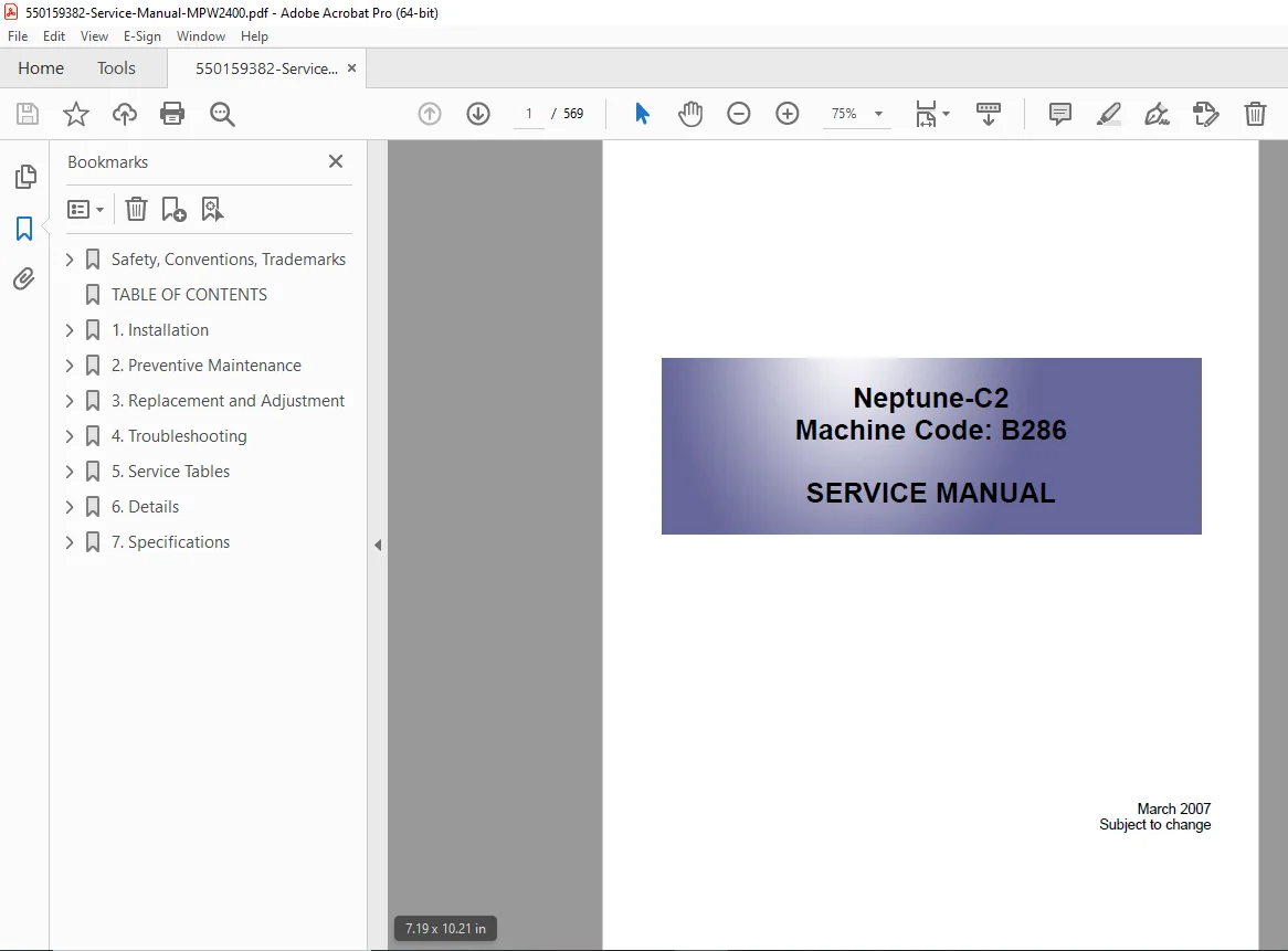
- Title: Neptune-C2 Service Manual
- Machine Code: B286
- Publication Date: March 2007
- Status: Subject to change
- Creator: XSL Formatter V4.0 MR4
- Pages: 569 pages
- File Size: 15.2 MB
- PDF Version: 1.4
SAFETY AND CONVENTIONS
Safety Precautions:
Prevention of Physical Injury:
- Unplug before disassembly/assembly
- Main power switch accessibility
- Voltage present even when switched off
- Keep hands away from electrified/mechanical components
- Start key operation warnings
- Fusing unit extreme heat warning
Health Safety Conditions:
- Never operate without ozone filters
- Replace ozone filters at proper intervals
- Toner/developer non-toxic but avoid eye contact
- First aid procedures for exposure
Electrical Safety Standards:
- Installation by trained service representatives only
- Completion of training course required
Safety and Ecological Notes for Disposal:
- Do not incinerate toner – ignition hazard
- Dispose per local regulations
- Lithium battery storage limits (100 per sealed box)
- Battery replacement warnings
- Proper disposal procedures
Manual Conventions:
- SEF/LEF paper feed direction notation
- Arrows indicate paper feed direction
- Horizontal = Main Scan Direction
- Vertical = Sub Scan Direction
- Symbol definitions (screws, connectors, E-rings, C-rings, harness clamps)
Warning and Caution Levels:
- WARNING: Death or serious injury possible
- CAUTION: Minor injury or machine damage
- NOTICE: Misfeeds, damage prevention
- TIP: Service tips and advice
Trademarks:
- Microsoft®, Windows®, MS-DOS®
- PostScript® (Adobe)
- PCL® (Hewlett-Packard)
- Ethernet® (Xerox)
- PowerPC® (IBM)
COMPLETE TABLE OF CONTENTS
CHAPTER 1: INSTALLATION (Pages 15-XX)
Preparation:
Environment:
- Temperature range: 10°C to 30°C (50°F to 86°F)
- Humidity range: 15% to 90% RH
- Ambient illumination: Less than 1,500 Lux
- Ventilation: More than 30 m³/hr/person
- Ambient dust: Less than 0.10 mg/m³
- Air conditioner/heater considerations
- Corrosive gas restrictions
- Altitude limit: 2,000m (6,600 ft) maximum
- Floor strength requirements
- Vibration considerations
Minimum Space Requirements:
- Front: 1000mm (40″)
- Back: 600mm (23″)
- Right: 600mm (23″)
- Left: 600mm (23″)
Machine Level:
- Front to back: Not more than 5mm from level
- Right to left: Not more than 0.15/1000mm from level
Power Source:
- Circuit breaker protection required
- 120V, 60 Hz, 15A or more
- 220-240V, 50/60 Hz, 10A or more
- Permissible voltage fluctuation: ±10%
- Power cord safety
- Dedicated circuit recommended
Installation Overview:
Installation Flow:
- Copier pre-installation (unpacking)
- Roll feeder or table installation
- Paper cassette installation (if applicable)
- SP and User Tool settings
- Copier final installation
- Printer/scanner options
- Folder unit installation (last)
SP and User Tool Settings Required:
- SP 2801-2: Lot Number 1 (toner)
- SP 2801-3: Lot Number 2 (toner)
- SP 2801-1: Developer Initial Setting
- SP 2923-1: Cleaning Blade Replace Mode
- SP 3001: ID Sensor Initial Setting
- Additional configuration settings
- Option registration
- Paper size settings
- Image quality adjustments
CHAPTER 2: MAINTENANCE (Pages XX-XX)
Scheduled Maintenance:
- Daily maintenance tasks
- Weekly maintenance tasks
- Monthly maintenance tasks
- Periodic maintenance intervals
- Consumables replacement
- Cleaning procedures
Component Replacement:
- Drum assembly replacement
- Developer unit replacement
- Toner cartridge replacement
- Charge corona unit
- Cleaning blade replacement
- Fusing unit components
- Scanner components
- Feed rollers
- Registration rollers
CHAPTER 3: DISASSEMBLY/ASSEMBLY (Pages XX-193)
General Disassembly Procedures:
- Cover removal procedures
- Access panel locations
- Screw identification
- Connector handling
- ESD precautions
Major Component Disassembly:
Scanner Section:
- Scanner unit removal
- CIS unit removal
- Original feed mechanism
- Drive components
- Sensor replacement
Drum Section:
- Drum cartridge removal
- Charge corona removal
- Cleaning unit removal
- Development unit removal
- Quenching lamp removal
Paper Feed Section:
- Roll feeder disassembly
- Manual feeder disassembly
- Paper cassette mechanism
- Registration roller assembly
- Paper exit components
Fusing Section:
- Fusing unit removal
- Hot roller removal
- Pressure roller removal
- Thermistor replacement
- Thermostat replacement
- Cleaning web replacement
Boards (Pages 193-209):
MCU/IPU/MB (Pages 193-196):
- Main Control Unit location
- Image Processing Unit
- Mother Board
- Board removal procedures
- Connector identification
- Replacement procedures
PSU/Circuit Breaker (Pages 197-198):
- Power Supply Unit
- Circuit breaker location
- Voltage testing
- Replacement procedures
Controller Board (Pages 199-201):
- Controller board location
- Communication interfaces
- Network connections
- Firmware updates
- Replacement procedures
NVRAM (Page 202):
- Non-Volatile RAM location
- Data backup procedures
- Battery replacement
- Configuration storage
T&S Power Pack (Page 203):
- Transfer and Separation power supply
- High voltage generation
- Safety precautions
- Testing procedures
RFDB – Roll Feeder Drive Board (Page 204):
- Roll feeder motor control
- Sensor interface
- Drive circuits
- Troubleshooting
SFDB – Sheet Feed Drive Board (Page 205):
- Sheet feeder motor control
- Paper detection
- Drive circuits
- Diagnostics
Others (Pages 207-209):
HDD (Page 207):
- Hard disk drive location
- Data storage
- Replacement procedures
- Data recovery
Cooling Fan, Ozone Filter (Page 208):
- Cooling fan locations
- Ozone filter replacement
- Airflow verification
- Maintenance schedule
SP Adjustments (Pages 210-225):
Image Adjustment with SP Codes (Pages 210-217):
- Image quality calibration
- Density adjustment
- Registration adjustment
- Color balance (if applicable)
- Test pattern printing
CIS Adjustment with SP Codes (Pages 218-220):
- Scanner calibration
- CIS sensor adjustment
- White level calibration
- Black level calibration
- Gain adjustment
LPH Adjustment with SP Codes (Pages 221-223):
- LED Print Head alignment
- Beam position adjustment
- Focus adjustment
- Power adjustment
LPH Density Adjustment with SP Codes (Page 224):
- Exposure power optimization
- Density uniformity
- Print quality verification
CHAPTER 4: TROUBLESHOOTING (Pages 227-265)
Service Call Conditions (Page 227):
- When to call for service
- Error code interpretation
- User troubleshooting limits
- Service technician requirements
SC Code Descriptions (Pages 228-246):
Complete Error Code Listings:
- SC1XXX: Scanner-related errors
- SC2XXX: Drum/imaging errors
- SC3XXX: Development system errors
- SC4XXX: Paper feed errors
- SC5XXX: Fusing errors
- SC6XXX: Paper exit errors
- SC7XXX: Communication errors
- SC8XXX: Controller errors
- SC9XXX: Option errors
For Each SC Code:
- Code number and description
- Probable causes
- Diagnostic procedures
- Corrective actions
- Component testing
- Replacement guidance
Jam Code Tables (Pages 247-252):
Overview (Page 247):
- Jam code structure
- Location identification
- Clearance procedures
Scanner Jams (Page 248):
- Original feed jams
- Sensor failures
- Drive mechanism issues
- Clearance procedures
Plotter (Printer) Jams (Page 250):
- Paper feed jams
- Registration jams
- Transfer jams
- Fusing jams
- Exit jams
Folder Unit Jams (Page 251):
- Folder mechanism jams
- Fold plate jams
- Stacker jams
Cover Open (Page 253):
- Cover interlock switches
- Safety interlocks
- Sensor verification
Fuses (Page 254):
- Fuse locations
- Fuse ratings
- Testing procedures
- Replacement procedures
Image Problem Troubleshooting (Pages 255-262):
Flow Chart (Page 255):
- Systematic diagnostic approach
- Problem isolation
- Decision tree
Scanning (Pages 256-258):
- Poor scan quality
- Lines or streaks
- Uneven density
- CIS problems
- Sensor issues
Printing (Pages 259-260):
- Poor print quality
- Density issues
- Streaks or bands
- Background fogging
- White spots
- Drum problems
- Development issues
- Fusing problems
Density Changes at CIS Joints (Page 261):
- CIS array alignment
- Joint calibration
- Density uniformity
Other Problems (Page 262):
- Unusual noises
- Overheating
- Performance degradation
Board LEDs (Pages 263-265):
PSU, MCU, IPU (Pages 263-264):
- LED status indicators
- Normal operation patterns
- Error indication patterns
- Diagnostic interpretation
SIB, VDB (Page 265):
- Scanner Interface Board LEDs
- Video Drive Board LEDs
- Status interpretation
CHAPTER 5: SERVICE TABLES (Pages 269-459)
Using the SP Mode (Page 269):
Direct Entry:
- SP mode access procedures
- Navigation methods
- Code entry
- Value adjustment
Firmware Update (Pages 271-272):
- Update overview
- Backup procedures
- Update procedures
- Verification testing
User Tools (Pages 273-279):
- User Tool summary
- Access procedures
- Available settings
- Configuration options
Input Check (Pages 280-284):
- Sensor status verification
- Switch status
- Signal monitoring
- Troubleshooting aid
Output Check (Pages 285-286):
- Motor operation testing
- Solenoid testing
- Clutch testing
- Actuator verification
SP Table Key (Page 287):
- SP code structure
- Parameter types
- Value ranges
- Default settings
SP1-xxx Feed (Pages 288-315):
- Paper feed adjustments
- Feed timing
- Registration timing
- Paper Thickness Default Selection (Page 299)
- Feed speed optimization
- Jam prevention
SP2-xxx Drum (Pages 316-329):
- Drum rotation speed
- Charge voltage
- Development bias
- Transfer voltage
- Cleaning parameters
- Drum maintenance counters
SP3-xxx Process Control (Page 330):
- Process timing control
- Sequence adjustments
- Synchronization
SP4-xxx Scanner (Pages 331-348):
- Scanner operation parameters
- CIS settings
- Scan timing
- Image processing
- Calibration settings
SP5-xxx Mode (Pages 349-399):
- Operating mode settings
- Copy mode parameters
- Print mode settings
- Special functions
- User preferences
SP6-xxx Peripherals (Pages 400-419):
- Option configuration
- Roll feeder settings
- Folder settings
- Paper cassette settings
- Interface settings
SP7-xxx Data Log (Pages 420-429):
- Counter values
- Usage statistics
- Maintenance counters
- Service history
SP8-xxx Data Log 2 (Pages 430-459):
- Extended logging
- Error history
- Performance data
- Diagnostic information
CHAPTER 6: DETAILS (Pages 461-558)
Overview (Page 461):
Machine General Layout (Pages 461-462):
- Overall system diagram
- Component identification
- Access points
Mechanical Component Layout (Pages 463-464):
- Mechanical assemblies
- Drive mechanisms
- Component locations
Drive Layout (Page 465):
- Motor locations
- Drive train
- Clutch positions
- Gear mechanisms
Original/Copy Paper Paths (Pages 466-467):
- Paper flow diagrams
- Path selection
- Sensor locations
Scanner (Pages 468-475):
Overview (Page 468):
- Scanner system description
- CIS technology
- Scanning process
Scanner Layout (Page 469):
- Component identification
- Assembly diagram
Original Width Detection (Pages 470-471):
- Width sensor operation
- Size detection
- Auto-selection
Original Drive Mechanism (Page 472):
- Feed motor
- Drive train
- Feed rollers
Original Feed Speed (Page 472):
- Speed specifications
- Variable speed control
Scanning Mechanism (Page 473):
- CIS operation
- Light source
- Sensor array
- Signal processing
Auto Image Density Correction (Pages 474-475):
- Density detection
- Automatic adjustment
- Reference standards
Image Processing (Pages 476-484):
General Image Processing Flowchart (Page 476):
- Signal flow
- Processing stages
- Enhancement functions
Original Modes (Pages 477-484):
- Text mode
- Photo mode
- Map mode
- Mixed mode
- Line drawing mode
- Background suppression
- Edge enhancement
Around the Drum (Pages 485-492):
Overview (Page 485):
- Drum subsystem components
- Process sequence
Drum Drive (Page 486):
- Drum motor
- Drive mechanism
- Speed control
Charge Corona Unit (Page 487):
- Corona wire
- Grid voltage
- Charging process
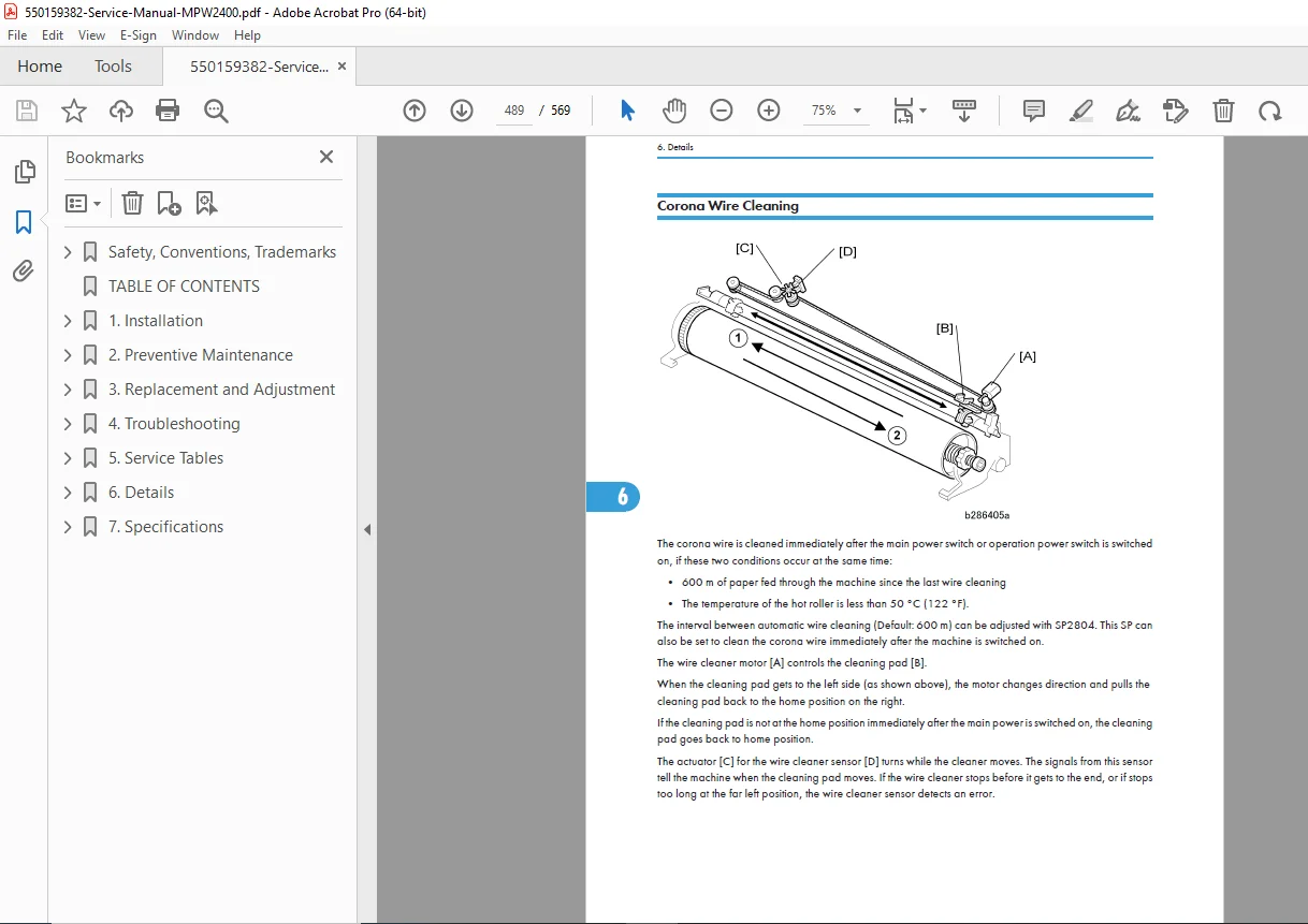
Corona Wire Cleaning (Page 488):
- Auto-cleaning mechanism
- Cleaning cycle
- Maintenance
Drum Cleaning (Page 489):
- Cleaning blade
- Toner collection
- Blade pressure
Collecting Used Toner (Page 490):
- Waste toner bottle
- Collection mechanism
- Disposal
Quenching (Page 491):
- Discharge lamp
- Residual charge removal
Drum Anti-Condensation Heaters (Page 492):
- Heater location
- Temperature control
- Humidity management
Image Writing (Page 493):
- LPH (LED Print Head)
- Exposure process
- Latent image formation
Development (Pages 494-504):
Overview (Page 494):
- Development system description
- Two-component developer
- Magnetic brush development
Development Drive Mechanism (Page 495):
- Developer roller drive
- Mixing mechanism
Toner Supply Mechanism (Page 496):
- Toner cartridge
- Supply auger
- Level control
Developer Cross-Mixing (Page 496):
- Developer circulation
- Mixing augers
- Toner distribution
Development Bias (Page 497):
- AC/DC bias voltage
- Development electric field
- Density control
ID Sensor (Page 498):
- Image Density sensor
- Toner concentration detection
- Feedback control
Warmup Control (Vsg Correction) (Page 498):
- Initial density adjustment
- Stabilization
Toner Density Control (Pages 499-501):
- Automatic toner replenishment
- ID sensor feedback
- Density target
- Mixing time control
Toner End/Near-End Detection (Pages 502-504):
- Toner level sensing
- Warning indicators
- Bottle replacement
Paper Feed and Registration (Pages 505-521):
Overview (Page 505):
- Paper handling subsystems
- Feed options
- Registration function
Manual Feed Mechanism (Pages 508):
- Manual insertion
- Feed rollers
- Width detection
Roll Feed Mechanism (Pages 509-511):
- Roll mounting
- Feed motor
- Tension control
- Width adjustment
Roll Feeder Paper Holders (Page 512):
- Paper holder types
- Installation
- Core support
Roll Paper Cutting Mechanism (Page 513):
- Cutter operation
- Cut timing
- Cutter blade maintenance
Roll End Detection (Pages 514-515):
- Roll end sensor
- Warning system
- Auto-switching (dual roll)
Paper Cassette Mechanism (Pages 516):
- Cassette installation
- Paper loading
- Size adjustment
Paper Cassette Feed (Pages 517-518):
- Feed motor
- Pickup roller
- Separation mechanism
Paper Cassette Paper End Detection (Page 519):
- Empty detection
- Warning indicators
Condensation Prevention (Page 520):
- Paper heater
- Humidity control
- Pre-warming
Paper Registration (Page 521):
- Registration rollers
- Timing adjustment
- Skew correction
- Image-to-paper alignment
Image Transfer and Separation (Pages 522-523):
Overview (Page 522):
- Transfer process
- Corona transfer
- AC separation
Pick-Off Pawl Operation (Page 523):
- Paper separation
- Pawl timing
- Jam prevention
Fusing Unit (Pages 524-538):
Overview (Page 524):
- Hot roller fusing
- Pressure application
- Temperature control
Paper Feed Through Fusing Unit (Page 525):
- Paper path
- Exit sensors
- Feed speed
Fusing Pressure Control Mechanism (Page 526):
- Pressure roller
- Spring mechanism
- Pressure adjustment
Hot Roller Thermistors and Thermostats (Page 527):
- Temperature sensing
- Safety thermostats
- Sensor locations
Temperature Control (Pages 527-535):
- PID control
- Target temperatures
- Warm-up control
- Standby control
- Paper thickness compensation
- Temperature profiles
Hot Roller Cleaning (Page 536):
- Cleaning web
- Web advance mechanism
- Maintenance
Fusing Unit Drive Mechanism (Page 537):
- Drive motor
- Drive train
- Speed control
Wrinkle Prevention (Page 538):
- Paper tension control
- Exit guide design
- Speed matching
Paper Exit (Pages 539-543):
Overview (Page 539):
- Exit paths
- Path selection
- Exit options
Switching the Paper Exit (Pages 541-542):
- Exit path solenoids
- Diverter gates
- Path routing
Paper Exit Drive (Page 543):
- Exit motor
- Exit rollers
- Speed control
Electrical Components (Pages 544-558):
Overview (Page 544):
- Electronic system architecture
- Board hierarchy
- Communication
Description of Electrical Components (Pages 547-553):
- Detailed component descriptions
- Function explanations
- Interconnections
MCU, IPU (Page 554):
- Main Control Unit circuits
- Image Processing Unit circuits
- Microprocessors
- Memory
PSU (Page 555):
- Power Supply circuits
- Voltage regulation
- Power distribution
SMDB, VDB, SIB (Page 556):
- Scanner Motor Drive Board
- Video Drive Board
- Scanner Interface Board
- Circuit descriptions
RFDB, SFDB (Page 557):
- Roll Feeder Drive Board
- Sheet Feed Drive Board
- Motor control circuits
GW Controller Board (Page 558):
- Gateway controller
- Network interface
- Communication protocols
CHAPTER 7: SPECIFICATIONS (Pages 559-569)
Main Machine (B286/B289) (Pages 559-562):
- Copy/print specifications
- Original size range
- Paper size range
- Copy/print speed
- Resolution
- Scale settings
- Dimensions
- Weight
- Power consumption
- Environmental specifications
Options (Pages 563-565):
Roll Feeder B851/B852 (Page 563):
- Paper width range
- Roll diameter
- Core size
- Weight capacity
- Dimensions
- Weight
Folder (D889) (Page 563):
- Fold patterns
- Paper size range
- Stacking capacity
- Dimensions
- Weight
Manual Feeder D333 (Page 564):
- Paper size range
- Feed capacity
- Dimensions
- Weight
Paper Cassette B853 (Page 565):
- Paper size range
- Capacity
- Dimensions
- Weight
Main Machine Configuration (Pages 566-569):
- System diagrams
- Option combinations
- Configuration matrix
Who Needs This Manual?
This Neptune-C2 (MPW2400) service manual is essential for:
- Certified imaging equipment technicians
- Wide format copier service companies
- Reprographic service specialists
- Engineering firm technical staff
- Architectural firm IT/technical staff
- Anyone performing authorized service on Neptune-C2 systems
Prerequisites:
✓ Service training on electrophotographic systems
✓ Wide format copier experience
✓ Electronic troubleshooting skills
✓ Mechanical repair aptitude
✓ Understanding of imaging systems
✓ Proper tools and test equipment
✓ ESD handling procedures
✓ High voltage safety training
FILE DETAILS
| Detail | Specification |
|---|---|
| Manual Title | Neptune-C2 Service Manual |
| Machine Code | B286 |
| Publication Date | March 2007 |
| Status | Subject to change |
| Pages | 569 pages |
| PDF Quality | Professional technical manual with detailed diagrams |
| File Size | 15.2 MB |
| Page Size | 517.96 x 735.44 pts |
| Language | English |
| Creator | XSL Formatter V4.0 MR4 for Linux |
| PDF Version | 1.4 |