Neurotherm NT-1100 RF Lesion Generator Service Manual – PDF
Original price was: $95.00.$18.95Current price is: $18.95.
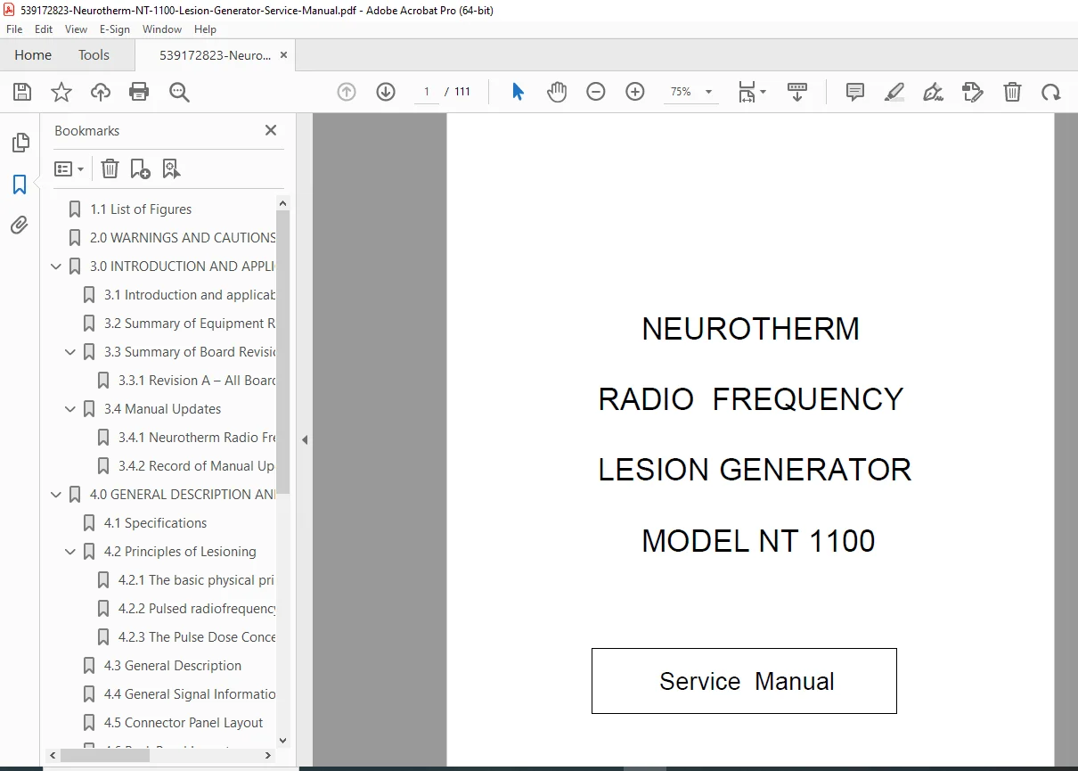
Factory service manual for Neurotherm NT-1100 Radio Frequency Lesion Generator covering thermal ablation, pulsed RF, and pulse dose modes. Includes complete circuit diagrams for 11 PCB modules, component maintenance, diagnostic procedures, and detailed specifications for pain management procedures. Features 480 KHz RF output, temperature control 50-90°C, multiple probe operation, and comprehensive troubleshooting.
Description
Neurotherm NT-1100 RF Lesion Generator Service Manual Pain Management – PDF DOWNLOAD
DESCRIPTION
This comprehensive factory service manual provides complete technical documentation for the Neurotherm NT-1100 Radio Frequency Lesion Generator, a sophisticated medical device used for pain management procedures including thermal ablation, pulsed radiofrequency therapy, and pulse dose treatments.
Equipment Overview & Applications
The Neurotherm NT-1100 is an advanced RF lesion generator designed for percutaneous pain management procedures including:
- Thermal RF Lesioning for facet joint denervation and medial branch neurotomy
- Pulsed Radiofrequency (PRF) for non-destructive neural modulation
- Pulse Dose Mode for standardized pulsed RF treatments
- Multiple Probe Operation for complex procedures (1, 2, or 3 probes)
- Cordotomy Procedures (optional special mode)
- Sympathetic Nerve Blocks and other interventional pain procedures
Technical Specifications
Physical Dimensions:
- Width: 400mm (15¾”)
- Height: 300mm (11¾”)
- Depth: 415mm (16½”)
- Weight: 12.5kg (28 lbs)
Electrical Requirements:
- Europe: 230V 50Hz, Fused 1 Amp (live and neutral)
- USA/Canada: 110V 60Hz, Fused 2 Amp (live and neutral)
- Power Consumption: 150 watts maximum
- Power Supply: Class 2 standard with double insulation
- Mains Transformer: Isolated bobbins with thermal fuses (125°C rated)
- Electrical Safety: Not connected to mains earth (Class 2 construction)
Compliance Standards:
- EN60601-1:1997 (Medical electrical equipment safety)
- IEC60601-1-2:1993 (EMC requirements)
- IEC60601-2-2:1998 (High frequency surgical equipment)
- IEC60601-2-10 with Canadian deviations
- UL60601-1, CAN/CSA C22.2 No.601.1 compliance
RF Lesion Mode Specifications
RF Output Characteristics:
- Waveform: 480 KHz ± 5% Sinusoidal
- Maximum Power Output: 30 watts ± 5% into 200 ohms
- Voltage Display: 0-99 RF volts (RMS) on-screen
- Current Display: 0-999 RF milliamps (RMS) on-screen
- Power Output: Continuously variable with real-time display
Temperature Control:
- Temperature Range: Selectable 50-90°C for thermal lesion (Default 80°C)
- Temperature Selection: 5°C steps in initial setup, 1°C steps during lesion mode
- Temperature Adjustment: “Temp Up” and “Temp Down” buttons for precise control
- Hardware Safety Cutoff: 95°C maximum temperature lockout
Timing Functions:
- Time Range: Selectable 0:30 to 10:00 minutes (Default 1:00 minute)
- Time Selection: 30-second steps in setup, 1-second steps during procedure
- Lesion Start Trigger: Automatic when temperature within 5°C of target
Special Temperature Profiles:
- Pre-programmed Profiles: P1, P2, P3 fixed temperature/time sequences
- Custom Profile Programming:
- Start Temperature: 50-60°C (Default 50°C)
- Step Time: 00:10 to 3:00 minutes (Default 2 minutes)
- Step Rise: 1°C or 5°C increments (Default 5°C)
- Final Temperature: 65-90°C (Default 65°C)
- Final Dwell Time: 1:00-10:00 minutes (Default 4:00 minutes)
Auto Mode Operation:
- Temperature ramps at 8°C per second
- Automatic timing starts when within 5°C of target temperature
- “Auto Start” and “Auto Stop” button control
- Requires RF Power Control initially set to zero (hardware/software lockout)
Pulsed RF Mode Specifications
Pulsed RF Parameters:
- Pulse Frequencies: 1, 2, 5, 10 Hz selectable
- Pulse Widths: 5, 10, 20, 50 milliseconds selectable
- Voltage Range: 30-70 Volts (Default 45 Volts) in Auto Mode
- Current Range: 50-350 mA in Auto Mode
- Temperature Limit: 42°C (prevents neurodestructive heating)
- Standard Paradigm: 20ms RF pulse followed by 480ms off time
Control Methods:
- Amplitude Control: Voltage modification to maintain temperature limit
- Pulse Width Control: Duration modification for temperature management
- Dual Mode Operation: Fixed voltage or fixed current selection
Pulse Dose Mode Specifications
Pulse Dose Characteristics:
- Set Temperature: 42°C fixed
- Pulse Counts: 120-1200 counts (Default 240 counts)
- Pulse Rate: 2 Hz fixed
- Pulse Width: 20 milliseconds fixed
- Voltage Range: 30-70V (Default 45V)
- Current Range: 50-350 mA
- Consistency Feature: Only delivers full-amplitude, full-duration pulses
- Temperature Management: Pauses delivery if temperature limit reached, resumes when below limit
Impedance Monitoring System
Impedance Measurement:
- Measuring Frequency: 53 KHz ± 3 KHz
- Measuring Source Voltage: Less than 500 mV AC
- Display Range: 50-2000 ohms with 1 ohm resolution
- Accuracy: ± 5%
- Measurement Modes: Available during all lesion modes and stimulation (when stimulation off)
Impedance Features:
- Internal Test Resistor: 500 ohm built-in calibration
- Audible Tone: Variable frequency tone corresponding to impedance (50-2000 ohms range)
- Tone Control: Adjustable volume and mutable
- Warning System: On-screen alerts for impedance <50 ohms or >2000 ohms
- Interlacing Function: RF output paused for ~25ms twice per second during lesioning for impedance measurement
Stimulation Mode Specifications
Stimulation Output:
- Signal Shape: Biphasic square wave with negative edge leading
- Voltage Ranges:
- 0-5V ± 3% for motor frequencies (2Hz and 5Hz)
- 0-3V ± 5% (Default) for sensory frequencies
- 0-0.5V ± 10% for low-intensity stimulation
- Current Ranges:
- 0-10mA ± 5% at 50-2000 ohms (motor)
- 0-6mA ± 5% at 50-2000 ohms (sensory default)
- 0-1mA ± 5% at 50-2000 ohms (low-intensity)
Stimulation Parameters:
- Motor Pulse Rates: 2 Hz or 5 Hz (Default 2 Hz)
- Sensory Pulse Rates: 10, 20, 50, 75, 100, 150, 180, 200 Hz (Default 50 Hz)
- Pulse Rate Accuracy: ± 3%
- Pulse Widths: 0.1, 0.2, 0.5, 1.0 milliseconds (Default 1.0 ms)
- Pulse Width Accuracy: ± 5% for 0.2, 0.5, 1.0 ms; ± 15% for 0.1 ms
Multiple Probe Operation
Probe Configuration:
- Probe Capacity: 1, 2, or 3 probes simultaneously
- Stimulation Mode: Individual probe selection by operator
- RF/Pulsed Mode: Time-interlaced energizing of all connected probes
- Probe Sockets: Three 4-pin output sockets on front panel
- Socket 1: Standard RF and Pulsed RF procedures
- Socket 2: Special procedures (dual/bipolar/cordotomy)
- Socket 3: Special procedures (multi-electrode applications)
Safety Features
Hardware Safety Systems:
- Hardware and software lockout if RF Power Control not initially at zero
- On-screen warnings for improper RF control settings
- LED indicator flashing during power delivery
- Hardware lockout at temperature >95°C
- Thermal fuses in all transformer windings (125°C rating)
- Double insulation (Class 2) for electrical shock prevention
- Built-in 150-ohm dummy load for self-testing
Diagnostic & Monitoring:
- Computer watchdog timer monitoring
- Real-time RF voltage and current monitoring
- Continuous impedance measurement during procedures
- Malfunction indication system
- Automatic output disable on error detection
Complete Table of Contents
1.0 Contents • List of 13 detailed figures and diagrams
2.0 Warnings and Cautions • Safety precautions for operators and patients • Electrical hazard warnings • Proper usage guidelines
3.0 Introduction and Applicability of This Manual • Manual scope and intended audience • Equipment revision history summary • Board revision changes (Revision A and B details) • Manual update procedures and record keeping
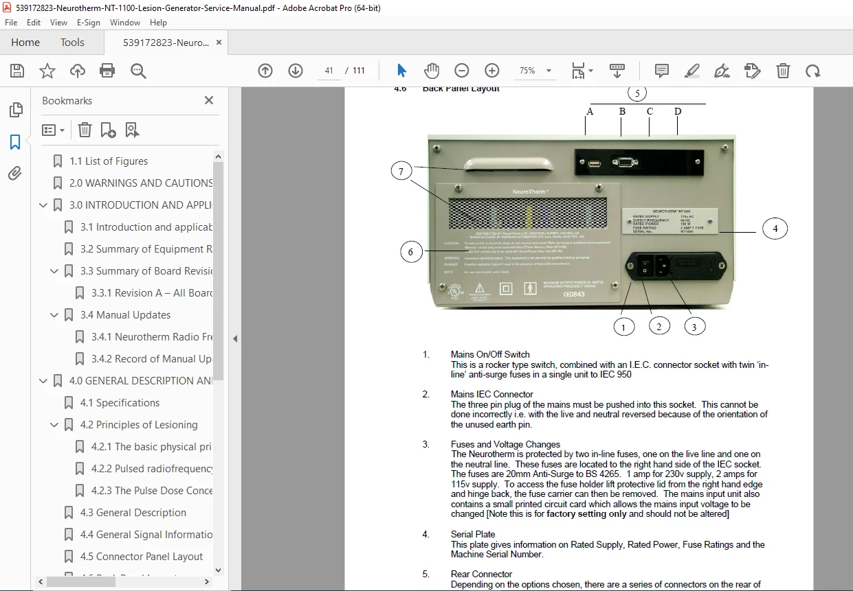
4.0 General Description and Principle of Lesioning • 4.1 Complete Specifications (as detailed above) • 4.2 Principles of Lesioning: – 4.2.1 Basic physical principles of radiofrequency ablation – 4.2.2 Pulsed radiofrequency theory and mechanisms – 4.2.3 Pulse Dose Concept and advantages • 4.3 General Description of NT-1100 architecture • 4.4 General Signal Information and processing • 4.5 Connector Panel Layout (front panel configuration) • 4.6 Back Panel Layout (rear connections and controls)
5.0 Detailed Description of Modules • 5.1 Power Entry Module: – Isolation transformer specifications – Power supply board operation – Thermal protection systems • 5.2 Fuse Board: – Fuse specifications and locations – Protection circuitry
6.0 Circuit Diagrams and Component Lists Complete schematics and component layouts for all 11 printed circuit boards:
• 6.1 Power Supply Board (RF100C) – Circuit diagram with voltage regulation – Component layout and part numbers – 67V, 12V, 14V secondary winding outputs
• 6.2 Fuse Board (RF101D) – Fuse protection circuit diagram – 75V DC fusing for RF amplifier – Component placement
• 6.3 Impedance Board (RF102D) – 53 KHz impedance measurement circuitry – Signal processing and display circuits – Audible tone generator circuit
• 6.4 Stimulate Board (RF103D + Sub Board) – Biphasic square wave generation – Pulse frequency and width control – BCD code interface for computer control – Motor and sensory stimulation circuits
• 6.5 RF Amplifier Board (RF104C) – 480 KHz sine wave generation – 30-watt power amplifier (200 ohm load) – 0-75 Vrms output range – Heat sink and cooling design – Low power cordotomy mode – Over-temperature protection – Short-circuit tolerance
• 6.6 RF Voltage and Current Metering Board (RF105C) – 75V DC supply switching – Toroid coil voltage/current detection – Full-wave rectification circuits – Analog output to computer interface – Test load switching (150 ohm, 100 watt) – Impedance interlacing timing circuits
• 6.7 Temperature Board (RF106D) – Thermocouple signal conditioning – Temperature measurement and display – Control algorithm circuits – 95°C safety cutoff circuit
• 6.8 Interlock Board (RF107D) – Safety interlock logic – RF enable/disable control – Probe connection detection – Error signal processing
• 6.9 Connection Board (RF109B) – Probe socket wiring and connections – Multi-probe switching matrix – Signal routing circuits
• 6.10 Interface Board (RF110D) – Computer I/O interface – Analog and digital signal conversion – Front panel control interface – Display driver circuits
• 6.11 Computer Mother Board (RF111B) – Microprocessor control system – BCD code output for mode selection – Analog input processing – Digital I/O management – Software enable/disable logic – Watchdog timer circuitry
Key Features for Biomedical Technicians
Circuit-Level Documentation:
- Complete schematic diagrams for all 11 PCB assemblies
- Detailed component layouts with reference designators
- Component value specifications and part numbers
- Signal flow diagrams and functional block descriptions
- Voltage test points and measurement procedures
Maintenance & Troubleshooting:
- Power supply verification procedures
- Impedance measurement calibration
- RF output power testing methods
- Temperature sensor verification
- Stimulation output testing
- Safety interlock testing procedures
- Fuse replacement specifications
Design Architecture:
- Modular board-level construction for serviceability
- Separate power domains for isolation
- Hardware and software redundant safety systems
- Test load integration for verification
- Front panel diagnostic LED indicators
Professional Applications
This service manual is essential for:
- Biomedical Equipment Technicians (BMETs) servicing hospital pain management equipment
- Medical Device Service Engineers performing warranty and post-warranty repairs
- Clinical Engineering Departments maintaining RF ablation systems
- Hospital Technical Services ensuring regulatory compliance
- Medical Equipment Distributors providing technical support
- Pain Management Clinics with in-house technical staff
- Training Programs educating biomedical technicians on RF generator technology
File Details
- Manual Name: Neurotherm Radio Frequency Lesion Generator Service Manual
- Model Covered: NT-1100
- Manual Revision: June 2006 (includes Revision A and B board changes)
- Manual Quality: Factory original PDF – Excellent quality with clear schematics
- Total Pages: 111 pages
- File Format: PDF (optimized, A4 size, searchable text)
- Language: English
- Publisher: Morgan Automation Ltd for Neurotherm
- Author: Erik Speekenbrink
This service manual provides factory-level technical information essential for maintaining EN60601 medical device compliance and ensuring safe, effective operation of this specialized pain management equipment.