New Holland 810LA 815LA 830LA 835LA 850LA 855LA 857LA 910LA 915LA 917LA 935LA 937LA 975LA Farm Loader Service Manual – Download
Original price was: $90.00.$37.95Current price is: $37.95.
New Holland 810LA 815LA 830LA 835LA 850LA 855LA 857LA 910LA 915LA 917LA 935LA 937LA 975LA Farm Loader Service Manual
Part Number : 60034447
Description
New Holland 810LA 815LA 830LA 835LA 850LA 855LA 857LA 910LA 915LA 917LA 935LA 937LA 975LA Farm Loader Service Manual
FILE DETAILS:
New Holland 810LA 815LA 830LA 835LA 850LA 855LA 857LA 910LA 915LA 917LA 935LA 937LA 975LA Farm Loader Service Manual
- Item Number:60034447
- Description:New Holland Farm Loader
- Language:English
- Type:PDF
- Model:810LA 815LA 830LA 835LA 850LA 855LA 857LA 910LA 915LA 917LA 935LA 937LA 975LA
NEW HOLLAND 810LA 815LA 830LA 835LA 850LA 855LA 857LA 910LA 915LA 917LA 935LA 937LA 975LA FARM LOADER SERVICE MANUAL – DOWNLOAD:
IMAGE PREVIEW:
SAMPLE PAGE FROM THE MANUAL:
New Holland 810LA 815LA 830LA 835LA 850LA 855LA 857LA 910LA 915LA 917LA 935LA 937LA 975LA Farm Loader Service Manual
- General information
- The operator’s safety and safety during maintenance are two of the most important things to consider when designing a new loader. As many safety features as possible are incorporated into the design.
- Every year, many accidents take place that could be avoided with a few seconds’ reflection and more careful loader/tractor operation and maintenance. Avoid personal injury.
- Read the following personal safety instructions and insist that everybody who works with you, or for you, also complies with the instructions.
- Only use implements that are approved by the manufacturer for use with the loader and control system. Incorrectly designed implements may cause personal injury and damage to the loader.
- For this reason, do not install third party implements without making sure they have been approved by the loader manufacturer.
TABLE OF CONTENTS:
New Holland 810LA 815LA 830LA 835LA 850LA 855LA 857LA 910LA 915LA 917LA 935LA 937LA 975LA Farm Loader Service Manual
1. Introduction…………………………………………………………………. 4
1.1. Necessary additional documentation………………………………………… 4
1.2. Identification………………………………………………………….. 5
1.2.1. Model and serial number…………………………………………….. 5
1.3. Alignment reference……………………………………………………… 6
1.4. Setting joystick position………………………………………………… 6
1.5. Subframe identification …………………………………………………. 7
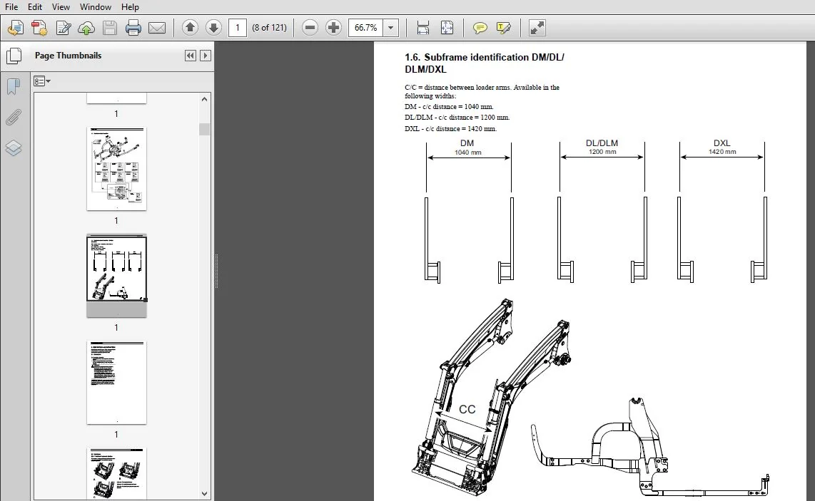
1.6. Subframe identification DM/DL/DLM/DXL……………………………………… 8
2. Description and definitions……………………………………………………. 9
2.1. Description…………………………………………………………….. 9
2.2. Definitions…………………………………………………………….. 10
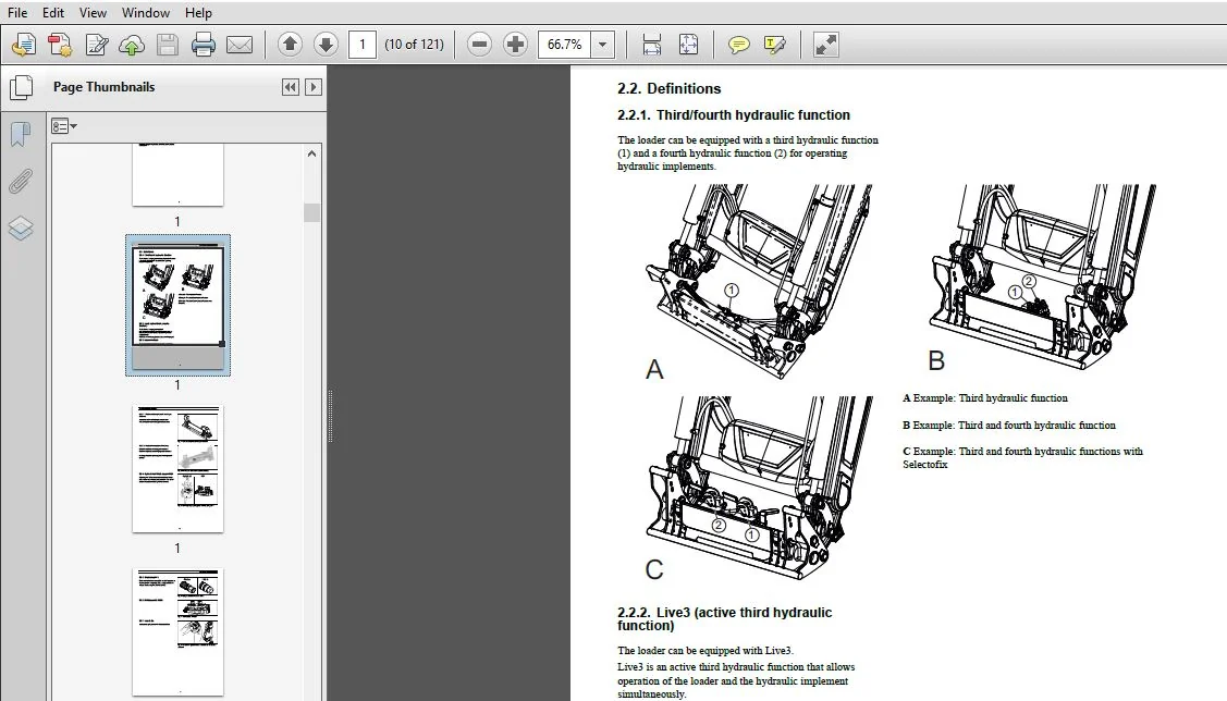
2.2.1. Third/fourth hydraulic function……………………………………… 10
2.2.2. Live3 (active third hydraulic function)………………………………. 10
2.2.3. Implement lock…………………………………………………….. 10
2.2.4. Hydro Quick / Multi-coupler MC4……………………………………… 11
2.2.5. Single couplers……………………………………………………. 12
2.2.6. Multicoupler 2 (MC2)……………………………………………….. 12
2.2.7. Lock & Go…………………………………………………………. 12
2.2.8. Position indicator…………………………………………………. 13
2.2.9. Compact Valve Unit (CVU)……………………………………………. 13
2.2.10. Hydraulic implement connection, Multi-coupler………………………… 14
2.2.11. Hose kit…………………………………………………………. 14
2.2.12. Soft Ride, Load Damping System……………………………………… 14
2.2.13. Material buckets………………………………………………….. 15
2.2.14. Heavy Duty Material Buckets………………………………………… 15
2.2.15. Construction Tooth Buckets…………………………………………. 15
2.2.16. Light Material/ Snow Buckets……………………………………….. 15
2.2.17. Fork Lifts……………………………………………………….. 16
2.2.18. Log Grab Attachment for Fork Lifts………………………………….. 17
2.2.19. Bale spike……………………………………………………….. 17
2.2.20. Big Bale Fork / with Backstop………………………………………. 17
2.2.21. Grapple with optional backscreen……………………………………. 18
2.2.22. Flexigrip 160, 200………………………………………………… 19
2.2.23. Quadrogrip 200……………………………………………………. 19
2.2.24. Weld on Hook Set………………………………………………….. 19
2.2.25. Systems DM, DL and DXL…………………………………………….. 20
2.2.26. Mechanical Self Levelling loader, MSL……………………………….. 20
2.2.27. Non-Self Levelling loader, NSL……………………………………… 20
2.2.28. Tool carrier……………………………………………………… 21
2.2.29. Implement………………………………………………………… 21
2.2.30. Implement hooks…………………………………………………… 21
3. Safety instructions…………………………………………………………… 23
3.1. General information……………………………………………………… 23
3.1.1. Guards……………………………………………………………. 23
3.1.2. Warning, prohibition and information decals…………………………… 23
3.2. Explanation of warning levels…………………………………………….. 23
3.2.1. Symbol explanation…………………………………………………. 24
3.2.2. Responsibility…………………………………………………….. 25
3.3. Installing the loader……………………………………………………. 25
3.4. Joystick operation………………………………………………………. 27
3.5. Protection equipment…………………………………………………….. 27
3.5.1. Service…………………………………………………………… 27
3.5.2. Welding…………………………………………………………… 27
3.5.3. Safety belt……………………………………………………….. 28
3.5.4. ROPS, Rollover protection structure………………………………….. 28
3.6. Operation………………………………………………………………. 28
3.6.1. Before work……………………………………………………….. 28
3.6.2. Operator/driver location……………………………………………. 29
3.6.3. Connecting implement……………………………………………….. 29
3.6.4. Workplace…………………………………………………………. 30
3.6.5. Stability…………………………………………………………. 32
3.6.6. Tractor stability………………………………………………….. 32
3.7. Risk factors……………………………………………………………. 33
3.7.1. During transport and work…………………………………………… 33
3.7.2. During service…………………………………………………….. 35
3.7.3. After work………………………………………………………… 36
3.8. Replacement parts……………………………………………………….. 37
3.9. Location of warning, prohibition and information decals (EU)…………………. 38
3.10. Location of warning, prohibition and information decals (NAFTA)……………… 39
3.11. Location of safety signs on implements……………………………………. 40
4. Installation – subframe……………………………………………………….. 42
4.1. Installation preparation – subframe……………………………………….. 42
4.2. Installation – subframe on tractor……………………………………….. 43
4.3. Installation checks – subframe installation……………………………….. 43
5. Installation – Front Loaders…………………………………………………… 44
5.1. Installation Preparation, Front Loaders……………………………………. 44
5.1.1. Lock & Go…………………………………………………………. 44
5.1.2. Position indicator…………………………………………………. 44
5.2. Connection – Front loader with subframe……………………………………. 45
5.2.1. Connecting the loader using lifting equipment…………………………. 45
5.2.2. Coupling a parked loader……………………………………………. 48
5.3. Checking front loader installation………………………………………… 50
5.4. Disconnecting-Front loader with subframe…………………………………… 52
5.4.1. Unhitching the loader using lifting equipment…………………………. 52
5.4.2. Disconnecting the loader……………………………………………. 54
6. Installation – Control system………………………………………………….. 56
6.1. Hose kit……………………………………………………………….. 56
6.2. Compact Valve Unit, CVU………………………………………………….. 56
6.2.1. CVU equipped with: Basic NSL (no extra functions)……………………… 56
6.2.2. CVU equipped with: Soft Ride + shock valves (tilt)…………………….. 57
6.2.3. CVU equipped with: Third hydraulic function…………………………… 57
6.2.4. CVU equipped with: Third function + Soft Ride…………………………. 57
6.2.5. CVU equipped with: Third function + hydraulic implement lock……………. 58
6.2.6. CVU equipped with: Third function + Soft Ride + hydraulic implement lock…. 58
6.2.7. CVU equipped with: Third and fourth hydraulic functions………………… 59
6.2.8. CVU equipped with: Live3…………………………………………… 59
6.2.9. CVU equipped with: Live3 + Soft Ride + shock valves (tilt)……………… 60
6.2.10. CVU equipped with: Live3 + hydraulic implement lock…………………… 60
6.2.11. CVU equipped with: Live3 + Soft Ride + hydraulic implement lock………… 61
7.0.12. The tractor’s own joystick………………………………………… 62
7. Service – general…………………………………………………………….. 62
8. Service – subframe……………………………………………………………. 63
9. Service – Front loaders……………………………………………………….. 64
9.1. Lubrication…………………………………………………………….. 64
9.2. Tool carrier…………………………………………………………… 64
9.3. Loaders………………………………………………………………… 65
9.3.1. Pins and bushings………………………………………………….. 65
9.3.2. Tool carrier, replacing pins and bushings…………………………….. 65
9.3.3. Replacing the pins and bushings, triangular link……………………… 67
9.3.4. Replacing pins and bushings, lift cylinder and bearing box……………… 67
9.4. Bearing box…………………………………………………………….. 69
10. Service – Loader hydraulics…………………………………………………… 70
10.1. Hydraulic system……………………………………………………….. 70
10.2. Hoses and connectors …………………………………………………… 70
10.2.1. Replacing hoses or connectors………………………………………. 71
10.3. Main hose kit………………………………………………………….. 71
10.4. Boom suspension………………………………………………………… 73
10.4.1. Replacing accumulators…………………………………………….. 73
10.5. Compact Valve Unit (CVU) with associated function modules…………………… 76
10.5.1. Module CB01 connecting block ”Basic” ……………………………….. 77
10.5.2. Module CB03 connecting block ”Soft Ride”…………………………….. 78
10.5.3. Module CB04 connecting block ”Tilt”…………………………………. 78
10.5.4. Module SV01 selector valve Third hydraulic function…………………… 79
10.5.5. Module SV02 selector valve fourth hydraulic function………………….. 80
10.5.6. Module IL01 Hydraulic lock valve…………………………………… 81
11. Service – Cylinders………………………………………………………….. 82
11.1. Tilt cylinder – Mechanical Self Levelling loader, (MSL)…………………….. 82
11.1.1. Tilt cylinder disassembly………………………………………….. 82
11.1.2. Removing the piston……………………………………………….. 85
11.1.3. Remove the piston seals……………………………………………. 85
11.1.4. Remove the top nut seals…………………………………………… 86
11.1.5. Remove the bottom guide seals………………………………………. 86
11.1.6. Installing new sealing components on the piston………………………. 86
11.1.7. Installing new sealing components on the top nut……………………… 86
11.1.8. Installing new sealing components on the bottom guide…………………. 87
11.1.9. Installing the top nut, piston and bottom guide on the piston rod………. 88
11.1.10. Final assembly – tilt cylinder…………………………………….. 88
11.2. Tilt cylinder – Non-Self Levelling loader (NSL)……………………………. 91
11.2.1. Tilt cylinder disassembly………………………………………….. 91
11.2.2. Removing the piston……………………………………………….. 93
11.2.3. Remove the piston seals……………………………………………. 94
11.2.4. Remove the top nut seals…………………………………………… 94
11.2.5. Installing new sealing components on the piston………………………. 94
11.2.6. Installing new sealing components on the top nut……………………… 94
11.2.7. Installing the bearing and the piston on the piston rod……………….. 95
11.2.8. Final assembly – tilt cylinder……………………………………… 96
11.3. Lift cylinder………………………………………………………….. 98
11.3.1. Tilt cylinder disassembly………………………………………….. 98
11.3.2. Removing the piston………………………………………………..100
11.3.3. Remove the piston seals…………………………………………….101
11.3.4. Remove the top nut seals……………………………………………101
11.3.5. Installing new sealing components on the piston……………………….101
11.3.6. Installing new sealing components on the top nut………………………101
11.3.7. Installing the bearing and the piston on the piston rod………………..102
11.3.8. Final assembly – lift cylinder………………………………………103
12. Troubleshooting………………………………………………………………105
12.1. Troubleshooting table – loaders…………………………………………..105
12.1.1. CVU………………………………………………………………108
13. Tightening torques……………………………………………………………110
13.1. Tightening torques………………………………………………………110
13.1.1. Table – Tightening torque…………………………………………..110
14. Storage……………………………………………………………………..111
15. Specifications……………………………………………………………….112
15.1. Mechanical self levelling, MSL……………………………………………113
15.2. Non self levelling, NSL………………………………………………….116
16. Wiring diagram……………………………………………………………….118
16.1. Wiring diagram – Loader………………………………………………….118
16.2. Wiring diagram -Loader with Live3…………………………………………119
16.3. Wiring diagram – Loader with all hydraulic functions………………………..120
PLEASE NOTE:
- This is the same manual used by the DEALERSHIPS to SERVICE your vehicle.
- The manual can be all yours – Once payment is complete, you will be taken to the download page from where you can download the manual. All in 2-5 minutes time!!
- Need any other service / repair / parts manual, please feel free to contact us at heydownloadss @gmail.com . We may surprise you with a nice offer