New Holland B110 B115 Loader Backhoe Tier 3 Service Manual 87643850 NA – PDF DOWNLOAD
Original price was: $78.95.$34.95Current price is: $34.95.
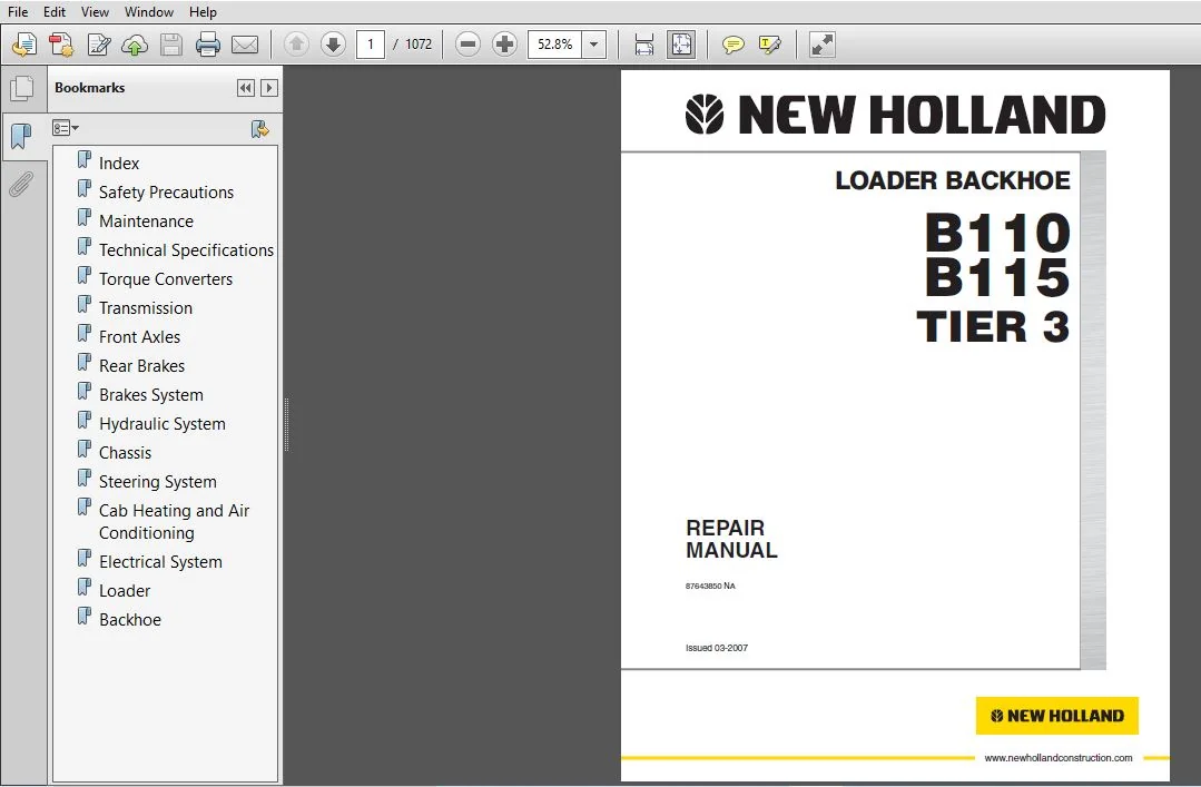
New Holland B110 B115 Loader Backhoe Tier 3 Service Manual
Part Number: 87643850NA
Description
New Holland B110 B115 Loader Backhoe Tier 3 Service Manual
FILE DETAILS:
New Holland B110 B115 Loader Backhoe Tier 3 Service Manual
Format: PDF
Language: English
Pages: 1072
Number: 87643850NA
Bookmarks: Yes
Searchable: Yes
Wiring Diagrams: Yes
Hydraulic Diagrams: Yes
DESCRIPTION:
New Holland B110 B115 Loader Backhoe Tier 3 Service Manual
SAFETY RULES:
Carefully follow specified repair and maintenance procedures. Do not wear rings, wristwatches, jewels, unbuttoned or flapping clothing such as ties, torn clothes, scarves, open jackets or shirts with open ips which could get hold into moving parts. We advise to use approved safety clothing such as anti-slipping footwear, gloves, safety goggles, helmets, etc. Never carry out any repair on the machine if someone is sitting on the operator’s seat, except if they are certified operators to assist in the operation to be carried out. Never operate the machine or use attachments from a place other than sitting at the operator’s seat.
- Never carry out any operation on the machine when the engine is running, except when specifically indicated. Stop the engine and ensure that all pressure is relieved from hydraulic circuits before removing caps, covers, valves, etc. All repair and maintenance operations should be carried out with the greatest care and attention.
- Service stairs and platforms used in a workshop or in the field should be built in compliance with the safety rules in force. Disconnect the batteries and label all controls to warn that the Machine is being serviced. Block the machine and all equipment which should be raised.
- Never check or fill fuel tanks and accumulator batteries, nor use starting liquid if you are smoking or near open flames as such fluids are flammable. Brakes are inoperative when they are manually released for maintenance purposes.
- In such cases, the machine should be kept constantly under control using blocks or similar devices. The fuel filling gun should remain always in contact with the filler neck. Maintain this contact until the fuel stops flowing into the tank to avoid possible sparks due to static electricity buildup. Use exclusively specified towing points for towing the machine.
- Connect parts carefully. Ensure that foreseen pins and/or locks are steadily fixed before applying traction. Do not stop near towing bars, cables or chains working under load. To transfer a failed machine, use a trailer or a low loading platform trolley if available.
- To load and unload the machine from the transportation mean, select a flat area providing a firm support to the trailer or truck wheels. Firmly tie the machine to the truck or trailer platform and block wheels as required by the forwarder. For electrical heaters, battery-chargers and similar equipment use exclusive auxiliary power supplies with a efficient ground to avoid electrical shock haard. Always use lifting equipment and similar of appropriate capacity to lift or move heavy components. Pay special attention to bystanders. Never pour gasoline or diesel oil into open, wide and low containers.
- Never use gasoline, diesel oil or other flammable liquids as cleaning agents. Use non-flammable non-toxic proprietary solvents. Wear protection goggles with side guards when cleaning parts using compressed air. Do not exceed a pressure of 2.1 bar, in accordance with local regulations.
- Do not run the engine in a closed building without proper ventilation. Do not smoke, use open flames, cause sparks in the nearby area when filling fuel or handling highly flammable liquids. Do not use flames as light sources when working on a machine or checking for leaks. Move with caution when working under a Machine, and also on or near a Machine.
- Wear proper safety accessories: helmets, goggles and special footwear. During checks which should be carried out with the engine running, ask an assistant to sit at the operator’s seat and keep the service technician under visual control at any moment. In case of operations outside the workshop, drive the machine to a flat area and block it. if working on an incline cannot be avoided, first block the Machine carefully.
- Move it to a flat area as soon as possible with a certain extent of safety. Ruined or plied cables and chains are unreliable. Do not use them for lifting or trailing. Always handle hem wearing gloves of proper thickness. Chains should always be safely fastened. Ensure that fastening device is strong enough to hold the load foreseen. No persons should stop near the fastening point, trailing chains or cables.
- The working area should be always kept CLEAN and DRY. Immediately clean any spillage of water or oil. Do not pile up grease or oil soaked rags, as they constitute a great fire haard. Always place them into a metal container. Before starting the Machine or its attachments, check, adjust and block the operator’s seat. Also ensure that there are no persons within the Machine or attachment operating range. Do not keep in your pockets any object which might fall unobserved into the Machine’s inner compartments.
TABLE OF CONTENTS:
New Holland B110 B115 Loader Backhoe Tier 3 Service Manual
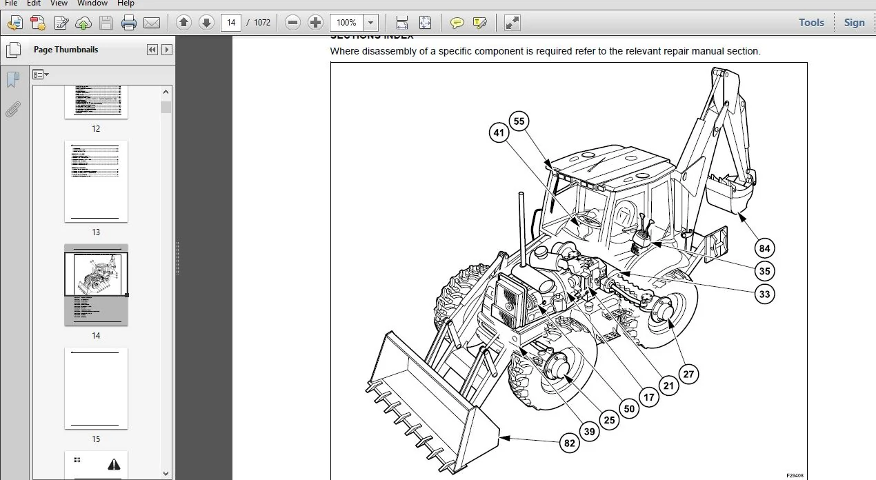
INDEX
SECTION 00 – SAFETY PRECAUTIONS
SECTION 01 – MAINTENANCE
SECTION 02 – TECHNICAL SPECIFICATIONS
1 LOADER BACKHOE MODELS 3
2 IDENTIFICATION OF MAIN COMPONENTS 4
3 TECHNICAL SPECIFICATIONS 5
4 LOADER ATTACHMENT DIMENSIONS AND PERFORMANCE 8
5 BACKHOE ATTACHMENT DIMENSIONS AND PERFORMANCE 10
6 LIFTING CAPACITIES 12
7 LOADER BUCKET WITH FORKS DIMENSIONS AND PERFORMANCE 14
8 FLUID AND LUBRICANT CAPACITIES AND SPECIFICATIONS 15
SECTION 17 – TORQUE CONVERTERS
1 POWERSHUTTLE TORQUE CONVERTER 3
11 DESCRIPTION AND OPERATION 3
12 TECHNICAL SPECIFICATIONS 4
13 OVERHAUL 4
14 INSPECTION 4
15 DISASSEMBLY AND ASSEMBLY 5
16 STALL TEST 5
17 FAULT FINDING 6
2 POWERSHIFT TORQUE CONVERTER 7
21 DESCRIPTION AND OPERATION 7
22 TECHNICAL SPECIFICATIONS 8
23 OVERHAUL 8
24 INSPECTION 9
25 DISASSEMBLY AND ASSEMBLY 9
26 STALL TEST 11
27 FAULT FINDING 12
SECTION 21 – TRANSMISSION
1 POWERSHUTTLE TRANSMISSION “TURNER MODEL COM-T4-2025” 3
11 TECHNICAL SPECIFICATIONS 3
12 TIGHTENING TORQUES 5
13 TRANSMISSION CONTROLS 6
14 LUBRICATION 11
15 TRANSMISSION OIL FLOW AND SUPPLY 12
16 TRANSMISSION HYDRAULIC VALVES AND PRESSURE TEST POINTS 18
17 TRANSMISSION POWER FLOW 19
18 TRANSMISSION 2WD COMPONENTS 23
19 TRANSMISSION 4WD COMPONENTS 26
110 TRANSMISSION REMOVAL 31
111 DISASSEMBLY AND ASSEMBLY 32
112 FAULT FINDING 90
2
113 SPECIAL TOOLS 93
2 POWERSHIFT TRANSMISSION “DANA T16000” 94
21 TECHNICAL SPECIFICATIONS 94
22 TRANSMISSION CONTROLS 95
23 LUBRICATION 105
24 PRESSURE SPECIFICATIONS AND CHECK POINTS 106
25 TRANSMISSION COOLER 108
26 TRANSMISSION HYDRAULIC DIAGRAM 109
27 OPERATION 110
28 POWER FLOWS 117
29 GEAR AND CLUTCH LAY OUT 132
210 TRANSMISSION / ENGINE REMOVAL FROM LOADER 133
211 TRANSMISSION COMPONENTS 137
212 DISASSEMBLY AND ASSEMBLY 155
213 SPECIAL TOOLS 264
214 FAULT FINDING 265
215 FAULT FINDING 267
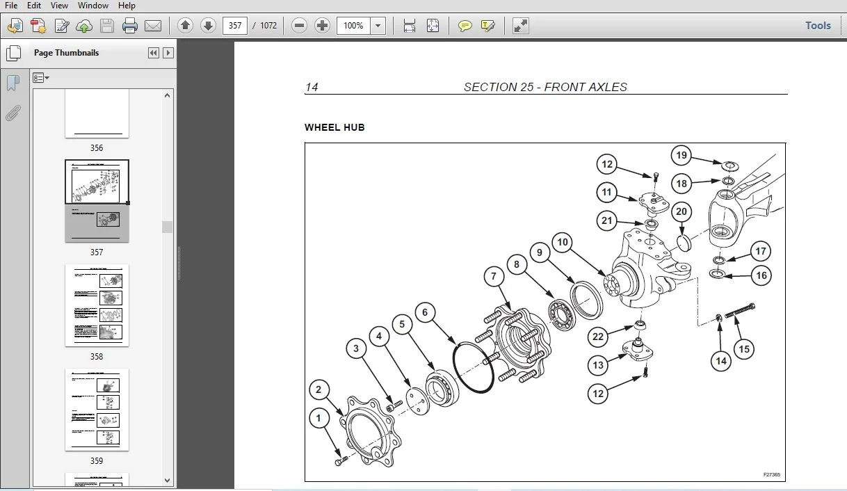
SECTION 25 – FRONT AXLES
1 FRONT AXLE 2WD “CARRARO” 3
11 TECHNICAL SPECIFICATIONS 3
12 DISASSEMBLY AND ASSEMBLY 5
13 FAULT FINDING 23
2 FRONT AXLE 4WD “CARRARO” 25
21 TECHNICAL SPECIFICATIONS 25
22 DISASSEMBLY AND ASSEMBLY 31
23 FAULT FINDING 77
3 FRONT AXLE 4WS “CARRARO” 80
31 TECHNICAL SPECIFICATIONS 80
32 DISASSEMBLY AND ASSEMBLY 84
33 FAULT FINDING 137
4 SPECIAL TOOLS 140
SECTION 27 – REAR AXLE
1 REAR AXLE 2WS 3
11 DESCRIPTION AND OPERATION 3
12 TECHNICAL SPECIFICATIONS 6
13 DISASSEMBLY AND ASSEMBLY 8
14 FAULT FINDING 27
2 REAR AXLE 4WS “CARRARO” 28
21 TECHNICAL SPECIFICATIONS 28
22 DISASSEMBLY AND ASSEMBLY 32
23 FAULT FINDING 81
3 SPECIAL TOOLS 84
SECTION 33 – BRAKES SYSTEM
1 TECHNICAL SPECIFICATIONS 3
2 HAND BRAKE 6
21 HAND BRAKE ADJUSTMENT 7
3
3 BRAKE MASTER CYLINDERS 8
31 BRAKE RESERVOIR 13
32 BRAKE BLEEDING PROCEDURE 13
SECTION 35 – HYDRAULIC SYSTEM
1 HYDRAULIC DIAGRAMS 3
11 HYDRAULIC DIAGRAM – 2WS MECHANICAL MODELS 3
12 HYDRAULIC DIAGRAM – 2WS PILOT MODELS 5
13 HYDRAULIC DIAGRAM – 4WS MECHANICAL MODELS 7
14 HYDRAULIC DIAGRAM – 4WS PILOT MODELS 9
2 HYDRAULIC PUMP 11
21 DESCRIPTION AND OPERATION 11
22 TECHNICAL SPECIFICATIONS 11
23 LOAD SENSING VALVE 13
24 REMOVAL 15
25 COMPONENTS 16
26 DISASSEMBLY AND ASSEMBLY 17
3 CONTROL VALVES 21
31 CONTROL VALVES “HUSCO” (B110 MECHANICAL MODELS) 21
32 CONTROL VALVES “REXROTH” (B115 MECHANICAL MODELS) 58
33 CONTROL VALVES “REXROTH” (B110 – B115 PILOT MODELS) 74
34 SOLENOID VALVE FOR PILOTING THE BACKHOE CONTROL VALVE
(WITH HYDRAULIC CONTROL) 82
35 ACCUMULATOR GLIDE RIDE “PARKER” 85
36 CIRCUIT RELIEF VALVES 88
4 HYDRAULIC SWING SYSTEM 98
41 DESCRIPTION AND OPERATION 98
42 HYDRAULIC OIL FLOW 99
43 PRECISION SWING CONTROL 101
5 HYDRAULIC CYLINDERS 104
51 LOADER CYLINDER 105
52 LOADER BUCKET CYLINDER 111
53 4X1 BUCKET CYLINDER 117
54 BACKHOE BOOM CYLINDER 120
55 BACKHOE CROWD CYLINDER 124
56 BACKHOE BUCKET CYLINDER 128
57 SHORT AND LONG TELESCOPIC CYLINDER 132
58 STABILIZERS CYLINDER 136
59 SWING CYLINDER 140
510 SPECIAL TOOLS 144
6 PILOT HYDRAULIC CONTROL LEVERS 145
61 TECHNICAL SPECIFICATIONS 145
62 DESCRIPTION AND OPERATION 146
63 DISASSEMBLY AND ASSEMBLY 149
64 PILOT HYDRAULIC CONTROL VALVE 152
7 FAULT FINDING AND FLOW TESTING 155
71 PRELIMINARY CHECKS 155
72 FAULT FINDING (WITH “HUSCO” CONTROL VALVES) 156
73 PRESSURE TESTING (WITH “HUSCO” CONTROL VALVES) 161
74 FAULT FINDING (WITH “REXROTH” CONTROL VALVES) 169
SECTION 39 – CHASSIS
1 DESCRIPTION AND OPERATION 3
2 REMOVAL AND INSTALLATION COMPONENTS 4
21 COMPONENTS WITHIN THE CHASSIS 4
22 COMPONENTS BELOW THE CHASSIS 5
23 COMPONENTS ATTACHED OUTSIDE THE CHASSIS 7
24 COMPONENTS ATTACHED ABOVE THE CHASSIS 8
25 TIGHTENING TORQUES 10
SECTION 41 – STEERING SYSTEM
1 STEERING SYSTEM 2WS 4
2 STEERING SYSTEM 4WS 7
3 STEERING MOTOR 12
31 TECHNICAL SPECIFICATIONS 13
32 COMPONENTS 15
33 DISASSEMBLY AND ASSEMBLY 16
34 SPECIAL TOOLS 33
35 FAULT FINDING 33
SECTION 50 – CAB HEATING AND AIR CONDITIONING
1 TECHNICAL SPECIFICATIONS 3
2 CAB HEATING 5
21 DESCRIPTION AND OPERATION 5
3 AIR CONDITIONING 12
31 PRINCIPALS OF AIR CONDITIONING 12
32 SAFETY PRECAUTIONS 17
33 DESCRIPTION AND OPERATION 18
34 FAULT FINDING AND TESTING 26
35 FLUSHING THE SYSTEM 44
36 EVACUATING THE SYSTEM 46
37 CHARGING THE SYSTEM 47
38 COMPONENTS OVERHAUL 48
39 COMPRESSOR 53
310 SPECIAL TOOLS 67
SECTION 55 – ELECTRICAL SYSTEM
1 GENERALITIES 3
11 TEMPORARY WIRING HARNESS REPAIR 3
12 FAULT FINDING 4
2 ELECTRICAL DIAGRAMS 5
21 ELECTRICAL DIAGRAMS – POWERSHUTTLE CAB 5
22 ELECTRICAL DIAGRAMS – POWERSHIFT CAB 22
23 ELECTRICAL DIAGRAMS – 4WS 38
24 ELECTRICAL DIAGRAMS – ROPS 55
3 CONTROLS AND INSTRUMENTS 69
31 FRONT INSTRUMENT PANEL 69
32 CALIBRATION OF SPEEDOMETER 71
33 SIDE INSTRUMENT PANEL 72
34 IMMOBILISER CIRCUIT 76
5
4 DIAGNOSTICS DISPLAY 77
41 SYMBOL 78
42 SETUP MENU 79
43 PROCEDURE ABOUT SELF TEST 81
44 ON BOARD ERROR CODE RETRIEVAL 82
45 BACKLIGHTING AND DIMMING 83
46 WORK HOURS 84
47 FUNCTIONAL DESCRIPTION 85
48 MAINTENANCE 91
49 WARNING MESSAGES 92
5 STARTING SYSTEM 98
51 DESCRIPTION AND OPERATION 98
52 FAULT FINDING 99
53 STARTER MOTOR 102
6 ALTERNATOR 108
61 TECHNICAL SPECIFICATIONS 108
62 DESCRIPTION AND OPERATION 108
63 COMPONENTS 110
64 REMOVAL 111
65 PRELIMINARY CHECK AND TESTS 112
66 FAULT FINDING 121
7 BATTERY 122
71 TECHNICAL SPECIFICATIONS 122
72 DESCRIPTION AND OPERATION 122
73 REMOVAL AND INSTALLATION 123
74 MAINTENANCE 125
75 TESTS 127
76 CONNECTING A BOOSTER BATTERY 129
77 BATTERY MASTER SWITCH 129
8 COMPONENT TESTING 130
81 GENERAL INTRODUCTION 130
82 COMPONENT TESTING 131
83 GROUND POINTS 131
84 KEY-START AND STOP SWITCH 133
85 ALTERNATOR 134
86 TRANSMISSIONS 134
87 PARKING BRAKE SWITCH 138
88 CAB 139
89 4WD SWITCH 144
810 BRAKE PEDAL SWITCHES 144
811 BRAKE OIL LEVEL SWITCH 145
812 FRONT WORK LAMP SWITCH – REAR WORK LAMP SWITCH (2) MAIN LIGHT SWITCH 145
813 HAZARD SWITCH 146
814 FLASHER MODULE 146
815 MULTI FUNCTION SWITCH 147
816 FRONT WIPER MOTOR (1) – REAR WIPER MOTOR (2) 147
817 4WS -STEERING SELECTOR SWITCH 148
818 STEERING CONTROL UNIT 149
819 4WS REAR AXLE STEERING SENSOR 151
820 4WS FRONT AXLE STEERING SENSOR 151
821 STEERING SOLENOIDS 152
822 DIFFERENTIAL LOCK SWITCH (1) 153
823 LOADER 154
6
824 BACKHOE 156
825 REVERSING BUZZER 160
826 FUEL LEVEL SENDER 160
SECTION 82 – LOADER
1 LOADER ATTACHMENT CONTROLS 4
2 LOADER BUCKET SELF LEVELING 7
3 LOADER ATTACHMENT SAFETY STRUT 10
4 LOADER BUCKET REMOVAL 12
5 LOADER ARM REMOVAL (B110) 15
6 LOADER ARM REMOVAL (B115) 17
SECTION 84 – BACKHOE
1 DESCRIPTION AND OPERATION 3
2 BACKHOE ATTACHMENT MECHANICAL CONTROLS 6
3 BACKHOE ATTACHMENT HYDRAULIC CONTROLS 14
4 REMOVAL AND INSTALLATION 16
5 TELESCOPIC DIPPER (HED) REVISION 23
NEW HOLLAND B110 B115 LOADER BACKHOE TIER 3 SERVICE MANUAL 87643850 NA – PDF DOWNLOAD:
IMAGES PREVIEW OF THE MANUAL:
PLEASE NOTE:
- This is the SAME exact manual used by your dealers to fix your vehicle.
- The same can be yours in the next 2-3 mins as you will be directed to the download page immediately after paying for the manual.
- Any queries / doubts regarding your purchase, please feel free to contact [email protected]