New Holland BB940A BB950A BB960A Baler Operation Manual PDF
Original price was: $56.95.$18.95Current price is: $18.95.
New Holland BB940A BB950A BB960A Baler Operators Manual
Description
New Holland BB940A BB950A BB960A Baler Operators Manual
FILE DETAILS:
New Holland BB940A BB950A BB960A Baler Operators Manual
Language : English
Pages : 314
Downloadable : YES
Format : PDF
Size : 5.06 MB
DESCRIPTION:
New Holland BB940A BB950A BB960A Baler Operators Manual
GENERAL:
This manual has been prepared to assist you in the correct procedure for running in, driving, operating, adjusting and maintaining your new machine. Thismachine has been designed and built to givemaximumperformance, economy and ease of operation under a wide variety of crops and conditions. Prior to delivery, your machine was carefully inspected both at the factory and by your dealer to ensure that it reaches you in optimum condition. To maintain this condition and ensure trouble–free operation it is important that routine services, as specified in this manual, are carried out at the recommended intervals.
- Before attempting to drive or operate your machine, read this manual carefully (especially chapter covering the Safety Precautions) and keep it in a convenient place for future reference. ”Left” and ”right” used throughout this manual are determined from the rear, facing in the direction of travel of the machine during operation. If at any time you require advice concerning your machine, do not hesitate to contact your authorised dealer.
- He has factory–trained personnel, genuine service parts and the necessary equipment to carry out your service requirements. IMPORTANT: This machine has been designed and built according to the European Directive EEC/89/392. Always use genuine New Holland Service Parts when servicing and repairing your machine and do not modify your machine without a written permission of themanufacturer. Failure to do so will void the responsibility of the manufacturer.
- An EC Declaration of Confirmity is separately delivered with your machine. Store this EC Declaration into the storage space for your Operator’s Manual (refer to section 2 — Controls, Instruments and Operation). Check local road legislation before driving the baler on public roads. When operating interchangeable New Holland built equipment, ensure the equipment is CE approved.
- As this publication is distributed throughout our international network, the equipment illustrated, either as standard or as an accessory, may vary according to the country in which the equipment is to be used. Low cost configurations, as chosen by the customer, may deviate from specifications given. Several illustrations in this manual show the safety guarding or the additional guards, legally required by certain countries, open or removed to illustrate better a particular feature or adjustment. Themachinemust not be used in this condition. For your own safety, ensure that all guards areclosed or replaced before operating the machine.
TABLE OF CONTENTS:
New Holland BB940A BB950A BB960A Baler Operators Manual
Title Page No
Section 1 – General Information And Safety 1–1
Intended Use 1–1
Product Identification 1–1
Airborne Noise Emission 1–2
Electromagnetic Compatibility (Emc) 1–2
Vibration Level Information 1–3
Legal Obligations 1–3
Safety Requirements For Fluid Power Systems And Components 1–3
Precautionary Statements 1–3
Safety Precautions 1–4
Wheels And Tyres 1–8
Angle Of Operation 1–8
Safety Decals 1–8
Needles/Knotter Safety Lock 1–20
Access To Machine Components 1–20
Protective Devices 1–23
Toolboxes 1–23
Lifting The Baler 1–24
Section 2 – Controls, Instruments And Operation 2–1
Controls, Indicators And Gauges 2–1
Flywheel Brake 2–1
Jack 2–1
Tractor Requirements 2–2
Horsepower Requirements 2–2
Tractor Drawbar / Tow Hitch 2–2
Tractor Wheel Setting 2–3
Power Take–off Shaft 2–3
Attaching The Baler To The Tractor 2–4
Attachment Of The PTO Shaft 2–18
Safety Chain / Safety Cable (Not For France) 2–20
Braking Systems 2–20
Fail Safe Brake Control (France Only) 2–20
Tractor Hydraulic Brake Connections (If Fitted)(*) 2–21
Tractor Pneumatic Brake Connections (If Fitted On The Baler)(*) 2–21
Tractor Hydraulic Connections 2–23
Tractor Electrical System 2–25
Baler Electrical System 2–26
InfoViewt monitor Installation 2–28
User Settings 2–55
Pickup Compensation Cylinder 2–66
Transporting The Baler 2–67
Starting The Baler 2–70
Parking The Baler 2–71
Pressure Gauge 2–72
Bale Length Control 2–73
Mechanical Bale Counter 2–73
NOT FOR REPRODUCTION
Table of Contents
ii
Section 3 – Field and Site operation 3–1
Description Of Operation 3–1
Product Feeding 3–6
Pick-up 3–6
CropCuttert Controls 3–11
Packer Units 3–11
Packer Cutter Units 3–12
Rotor Cutter Units 3–16
Unplugging The Rotor Cutter System 3–26
Pre-compression Chamber 3–27
Stuffer Trip Sensitivity Lever 3–27
Stuffer 3–28
Charge Holding Fingers 3–29
Pressing 3–30
Plunger/Bale Chamber 3–30
Hay Dogs 3–30
Bale Density System 3–31
General 3–31
Automatic Bale Density Control 3–32
Manual Bale Density Control 3–34
Manual Override Bale Density Control 3–36
Tying 3–37
General 3–37
Knotter / Needle Drive Components 3–38
Threading The Baler 3–39
Knotters 3–45
Monitoring Flags 3–45
Missed Knots 3–47
Ejection 3–47
Bale–chute 3–47
Bale-ejectt System (If Fitted) 3–51
Removing A Bale From The Bale Chamber 3–52
Tandem Auto-steer Axle (If Fitted) 3–55
Operation 3–55
Auto-steer Lock-out Valve 3–57
Shearbolts 3–58
Baling 3–59
Windrow/Swath Size 3–60
Before Using The Machine 3–60
Knives 3–60
Starting To Bale 3–61
Empty Bale Chamber Start-up 3–62
Continued Baling 3–62
Performance Checks 3–63
Section 4 – Lubrication And Maintenance 4–1
Lubrication 4–1
General Information 4–1
Lubrication And Maintenance Quick Reference 4–2
Service At 10 Hours, 400 Bales Or Daily 4–4
Centralized Greasing System 4–4
Automatic Greasing System (If Installed) 4–14
Remaining Conventional Grease Points 4–16
Service At 50 Hour Or 2000 Bales Or Weekly 4–18
Pto Drive Line Greasing 4–18
Automatic Oiling System 4–21
Linkages, Threaded Rods And Pivots 4–23
Ball Ring Hitch And Wear Plate 4–23
Main Drive Gearbox 4–24
Stuffer Drive Gearbox 4–25
Knotter Drive Gearbox 4–26
Bale Density Hydraulic Circuit 4–27
General Information 4–29
Chains 4–30
Packer/Rotor Drive Chain 4–30
Pick–up Main Drive Chain And Pick–up Reel Drive Chain 4–31
Pick–up Auger Drive Chain 4–31
Main Drive 4–33
PTO Drive Slip Clutch 4–33
Burnishing The Slip Clutch 4–33
Service At 100 Hours Or 4000 Bales Or Monthly 4–34
Flywheel Brake 4–34
Product Feeding 4–36
Pick–up Slip Clutch 4–36
Pick-up Tine Replacement 4–37
Auger Stripper Plates 4–38
Packer Slip Clutch 4–39
Rotor Cut-out Clutch 4–40
Knife Drawer Adjustments 4–41
Cropcutter Knife Sharpening 4–42
Pressing 4–44
Stuffer Brake 4–46
Stuffer Fingers To Plunger Timing 4–47
Crop Holding Fingers 4–49
Stuffer Adjustment 4–50
Plunger/Bale Chamber 4–51
Hay Dogs 4–53
Twine Tying Mechanism 4–54
Twine Tension 4–55
Description Of The Knotter Assembly 4–56
Knotter Adjustments 4–57
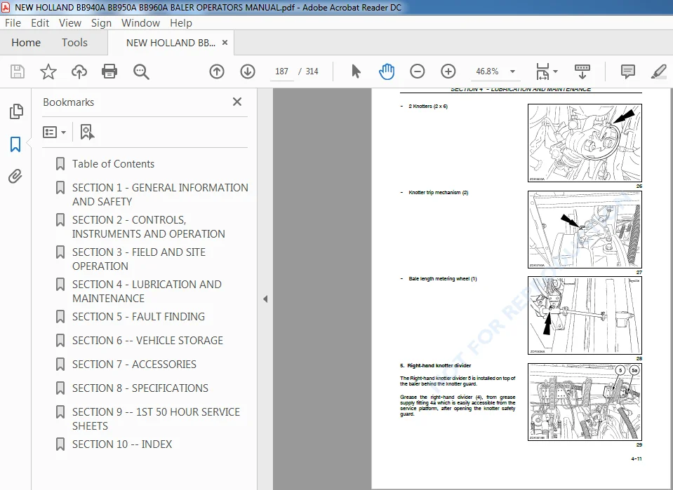
Knotter Trip Mechanism 4–60
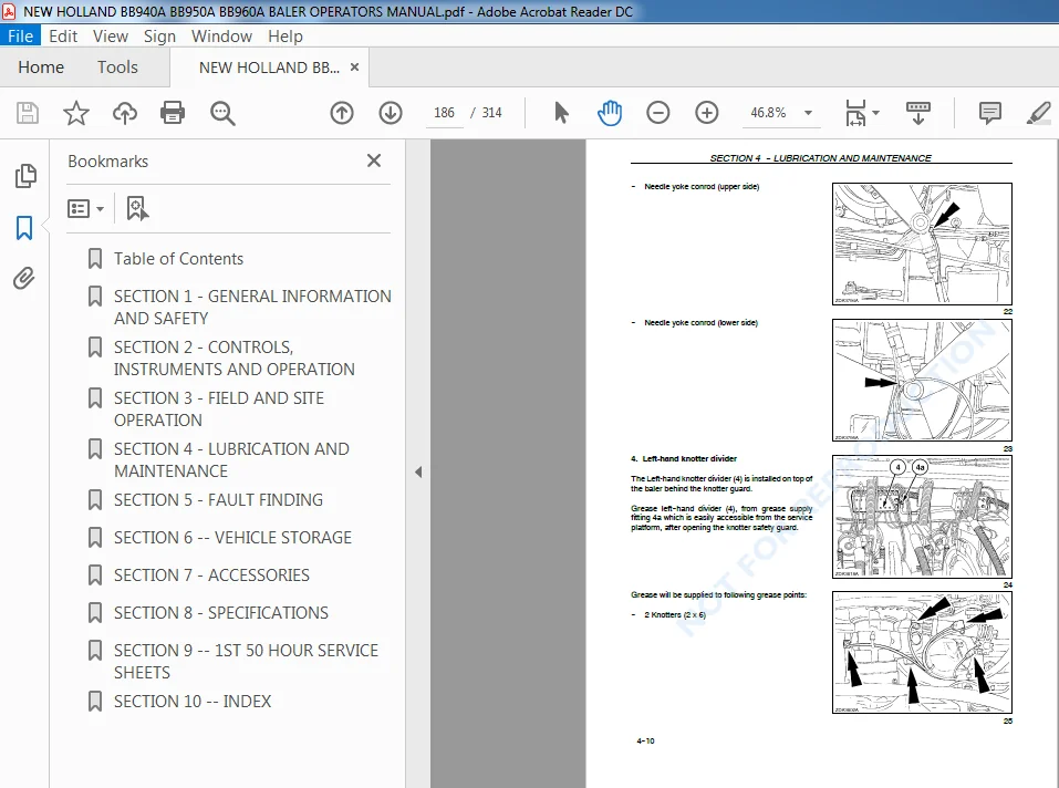
Needle Adjustment 4–62
Maximum Needle Penetration 4–63
Needles To Plunger Timing / Knotter Drive Shearbolt Replacement 4–65
Tucker Arm Alignment 4–66
Needle Carriage Support 4–67
Needle Brake 4–67
Needle Protection Linkage 4–69
Table of Contents
iv
Section 4 – Lubrication And Maintenance 4–1
Twine Fingers 4–70
Electrical System 4–72
Power Distribution 4–75
Overriding 4–75
Lights-bulb Replacement 4–77
Hydraulic System 4–79
Wheels And Tyres 4–80
Brake System (If Fitted) 4–81
Hydraulic Brake System (If Fitted) 4–81
Air Brake System (If Fitted) 4–83
Cleaning The Baler 4–84
Section 5 – Fault Finding 5–1
Tying 5–1
Product Feeding 5–8
Drives 5–9
Bale Shape 5–11
Integrated Automatic Oiler 5–12
Bale Density Regulation 5–13
Packer Cutter System 5–14
Rotor Cutter System 5–15
Electrical System 5–16
Section 6 — Vehicle Storage 6–1
End-of-season Service 6–1
Ordering Parts And/Or Accessories 6–2
Preseason Service 6–3
Section 7 – Accessories 7–1
Tractor Drawbar Kit 7–1
Hard Faced Cutter Knives 7–1
Working Light Kit 7–2
Revolving Flashlight 7–2
InfoViewt Monitor Support 7–2
Automatic Greasing Pump 7–2
Quick Fill Pump 7–3
Bale Eject System 7–3
Fill Flow Kit 7–3
Plate Bale Chute 7–3
Roller Bale Chute 7–4
Printer 7–4
Section 8 – Specifications 8–1
Overall Measurements 8–3
Technical Data 8–4
Section 9 — 1st 50 Hour Service Sheets 9–1
Check And Adjust, As Required (Customer Copy) 9–1
Check And Adjust, As Required (Dealer Copy) 9–3
Section 10 — Index 10–1
NEW HOLLAND BB940A BB950A BB960A BALER OPERATORS MANUAL – PDF DOWNLOAD:
IMAGES PREVIEW OF THE MANUAL:
PLEASE NOTE:
- This is the same manual used by the dealers to diagnose and troubleshoot your vehicle
- You will be directed to the download page as soon as the purchase is completed. The whole payment and downloading process will take anywhere between 2-5 minutes
- Need any other service / repair / parts manual, please feel free to contact [email protected] . We still have 50,000 manuals unlisted