NEW HOLLAND E16 E18 Workshop Manual 604.13.396 – PDF DOWNLOAD
Original price was: $78.00.$28.95Current price is: $28.95.
NEW HOLLAND E16 E18 Workshop Manual 604.13.396 – PDF DOWNLOAD
Description
NEW HOLLAND E16 E18 Workshop Manual 604.13.396 – PDF DOWNLOAD
IMAGES PREVIEW OF THE MANUAL:
DESCRIPTION:
NEW HOLLAND E16 E18 Workshop Manual 604.13.396 – PDF DOWNLOAD
INTRODUCTION
- This service manual has been prepared in order to increase repair quality, providing to the technicians the elements for a good knowledge of the product and showing the proper procedures to carry out the maintenance operations.
- We recommend to thoroughly read the content and follow it when necessary. It is a concise guide. It covers construction features, operation principle, troubleshooting, disassembly and assembly of components and repair action.
- Using this manual in systematic and rational way it is possible to reduce the repairing errors and delay that could cause machine stop with a detriment of cost management.
- The information quoted in this service manual are supplied also to be used for training aids. Therefore it is advisable to be used in the training of new personnel that will be employed in the machine maintenance.
SAFETY PRECAUTIONS
GENERALITIES
- Read the Operation and Maintenance Instruction Manual carefully before starting, operating, maintaining, fuelling or servicing the machine. Carefully read the explanation to each and all safety signs in the special section of this Manual before starting, operating, maintaining, fuelling or servicing the machine.
- Machine-mounted safety plates are colour coded yellow with black borders when they refer to points where special WARNING must be paid and failure to observe them may cause a serious DANGER to the integrity of machine operators.
- They are white with red borders and black lettering when they refer to a FORBIDDEN practice. It is fundamental that all machine operators know very well the meaning of each safety plate as this considerably decreases operating hazards and accidents. Do not allow unauthorised personnel to operate or service this machine.
- Do not wear rings, wrist watches, jewellery, loose or hanging garments, such as ties, torn clothing, scarves, unbuttoned or unzipped jackets that can get caught in moving parts. Wear certified safety clothes such as: hard hat, noslip footwear, heavy gloves, ear protection, safety glasses , reflector vests, respirators every time the job requires it.
- Ask your employer about safety regulations in force and protective equipment. Always keep the operator’s compartment, step plates, grab-rails and handles clean and clear of foreign objects, oil, grease, mud or snow to minimise the danger of slipping or stumbling. Remove mud or grease from your shoes before operating the machine. Do not jump on or off the machine.
- Always keep both hands and one foot, or both feet and one hand in contact with steps and/or grab rails. Do not use controls or hoses as hand holds. Hoses and controls are movable parts and do not provide solid support.
- Besides, controls may be inadvertently moved and cause unexpected movement of the machine or its attachments.
- Never operate the machine or its attachments from any position other than sitting in the driver’s seat. Keep head, body, limbs, hands and feet inside the operator’s compartment at all times to reduce exposure to external hazards.
- Be careful of possible slippery conditions of the steps and hand rails as well as of the ground around the machine. Wear protective boots or shoes with the soles made of highly no-slip rubber.
- Do not leave the machine until it has come to a complete stop. Always check height, width and weight limitations which may be encountered in the working site and ensure the machine does not exceed them.
- Assess exact paths of gas ducts, water mains, telephone lines, sewers, overhead and underground electric lines and all other possible obstacles. Such paths should be opportunely defined by competent Authorities.
- If necessary, require that the service is interrupted or said installations are moved prior to starting the work.
- You must know the working capacity of the machine. Define the rear upperstructure swing area and provide for opportune barriers to prevent access into it.
- Never exceed machine lifting capacity. Remain within the limits shown in the loading capacity chart located on the machine
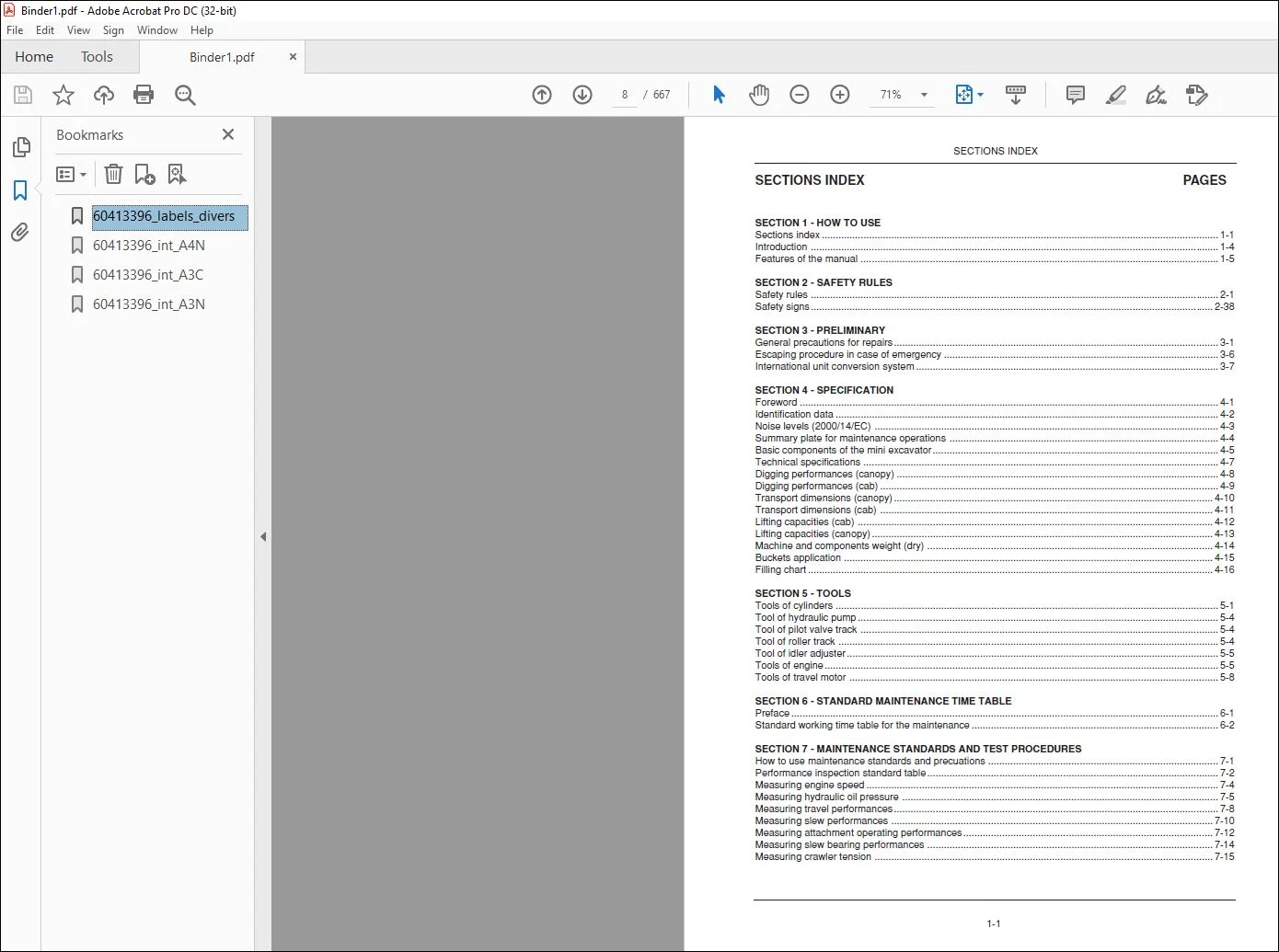
TABLE OF CONTENTS:
NEW HOLLAND E16 E18 Workshop Manual 604.13.396 – PDF DOWNLOAD
Sections index 1-1
Introduction 1-4
Manual handling 1-4
Symbols and indications 1-5
Features of the manual 1-6
Manual composition 1-6
Brief information for manual consultation 1-8
SECTION 1 – HOW TO USE
Sections index 1-1
Introduction 1-4
Features of the manual 1-5
SECTION 2 – SAFETY RULES
Safety rules 2-1
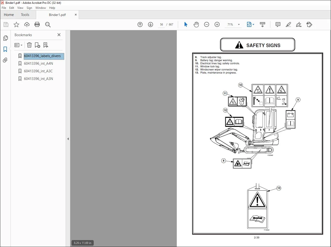
Safety signs 2-38
SECTION 3 – PRELIMINARY
General precautions for repairs 3-1
Escaping procedure in case of emergency 3-6
International unit conversion system 3-7
SECTION 4 – SPECIFICATION
Foreword 4-1
Identification data 4-2
Noise levels (2000/14/EC) 4-3
Summary plate for maintenance operations 4-4
Basic components of the mini excavator 4-5
Technical specifications 4-7
Digging performances (canopy) 4-8
Digging performances (cab) 4-9
Transport dimensions (canopy) 4-10
Transport dimensions (cab) 4-11
Lifting capacities (cab) 4-12
Lifting capacities (canopy) 4-13
Machine and components weight (dry) 4-14
Buckets application 4-15
Filling chart 4-16
SECTION 5 – TOOLS
Tools of cylinders 5-1
Tool of hydraulic pump 5-4
Tool of pilot valve track 5-4
Tool of roller track 5-4
Tool of idler adjuster 5-5
Tools of engine 5-5
Tools of travel motor 5-8
SECTION 6 – STANDARD MAINTENANCE TIME TABLE
Preface 6-1
Standard working time table for the maintenance 6-2
SECTION 7 – MAINTENANCE STANDARDS AND TEST PROCEDURES
How to use maintenance standards and precuations 7-1
Performance inspection standard table 7-2
Measuring engine speed 7-4
Measuring hydraulic oil pressure 7-5
Measuring travel performances 7-8
Measuring slew performances 7-10
Measuring attachment operating performances 7-12
Measuring slew bearing performances 7-14
Measuring crawler tension 7-15
SECTION 8 – HYDRAULIC SYSTEM
Function and features of hydraulic circuit 8-1
Hydraulic circuits and components 8-2
Hydraulic circuit operation 8-6
SECTION 9 – ELECTRICAL SYSTEM
How to read circuit diagram 9-1
SECTION 10 – ATTACHMENT
Attachment assy and name 10-1
Bucket 10-2
Arm 10-5
Boom 10-10
Swing 10-15
Dozer 10-22
Hydraulic cylinders 10-26
SECTION 11 – UPPER STRUCTURE
Canopy 11-1
Cab 11-4
Guard 11-6
Floor plate 11-10
Battery 11-13
Counterweight 11-14
Fuel tank 11-17
Hydraulic oil tank 11-20
Air cleaner 11-25
Muffler 11-27
Hydraulic pump 11-28
Radiator 11-43
Engine 11-47
Control valve 11-49
Solenoid valve 11-84
Pilot valve 11-86
Pilot valve travel 11-96
Slew motor 11-105
Joint swivel 11-139
Selector valve 11-154
Upper frame 11-159
SECTION 12 – TRAVEL SYSTEM
Low structure 12-1
Crawler 12-3
Slide plate 12-12
Roller tracks 12-14
Idler adjuster 12-19
Sprocket 12-28
Travel motor 12-29
Slew bearing 12-71
Lower frame 12-76
SECTION 13 – TROUBLESHOOTING HYDRAULIC SYSTEM
General precautions 13-1
Trouble diagnosis: Hydraulic 13-2
Troubleshooting 13-3
SECTION 14 – TROUBLESHOOTING ELECTRICAL SYSTEM
Trouble diagnosis: Electrical 14-1
Troubleshooting 14
SECTION 15 – TROUBLESHOOTING ENGINE
Trouble diagnosis: Engine 15-1
Troubleshooting 15-2
SECTION 16 – ENGINE
Specifications and Performance 16-1
Cross Sectional Views 16-15
Cooling water, lubricating oil and fuel oil 16-17
Troubleshooting 16-21
Measuring instruments 16-25
Measurement, inspection and adjustment 16-29
Adjustment the valve head clearance 16-31
Checking the v-belt tension 16-32
Measuring and checking the injection pressure and spray patterns of the fuel injection valve 16-32
Checking and adjustament the fuel injection timing 16-36
Adjustament the no-load maximum (or minimum) revolutions 16-38
Checking the cooling water system and radiator for water leakage 16-38
Checking the battery 16-39
Checking the sensors 16-41
Checking the oil cooler 16-42
Checking the piston cooling nozzle 16-43
Measuring Procedure, Service Data and Corrective Action 16-45
Disassembly and reassembly 16-73
Service data 16-83
Tightening torque 16-89
Fuel injection pump for indirect injection system 16-91
Fuel Injection Pump for Direct Injection System 16-97
Governor 16-111
Turbocharger 16-123
Need help? Contact: [email protected]
https://vimeo.com/731606710
PLEASE NOTE:
- This is the same manual used by the dealers to diagnose and troubleshoot your vehicle
- You will be directed to the download page as soon as the purchase is completed. The whole payment and downloading process will take anywhere between 2-5 minutes
- Need any other service / repair / parts manual, please feel free to contact [email protected] . We still have 50,000 manuals unlisted
S.M