New Holland F106.6 F106.6A F156.6 F156.6A Grader Service Repair Manual 87726937A – PDF DOWNLOAD
Original price was: $56.95.$27.95Current price is: $27.95.
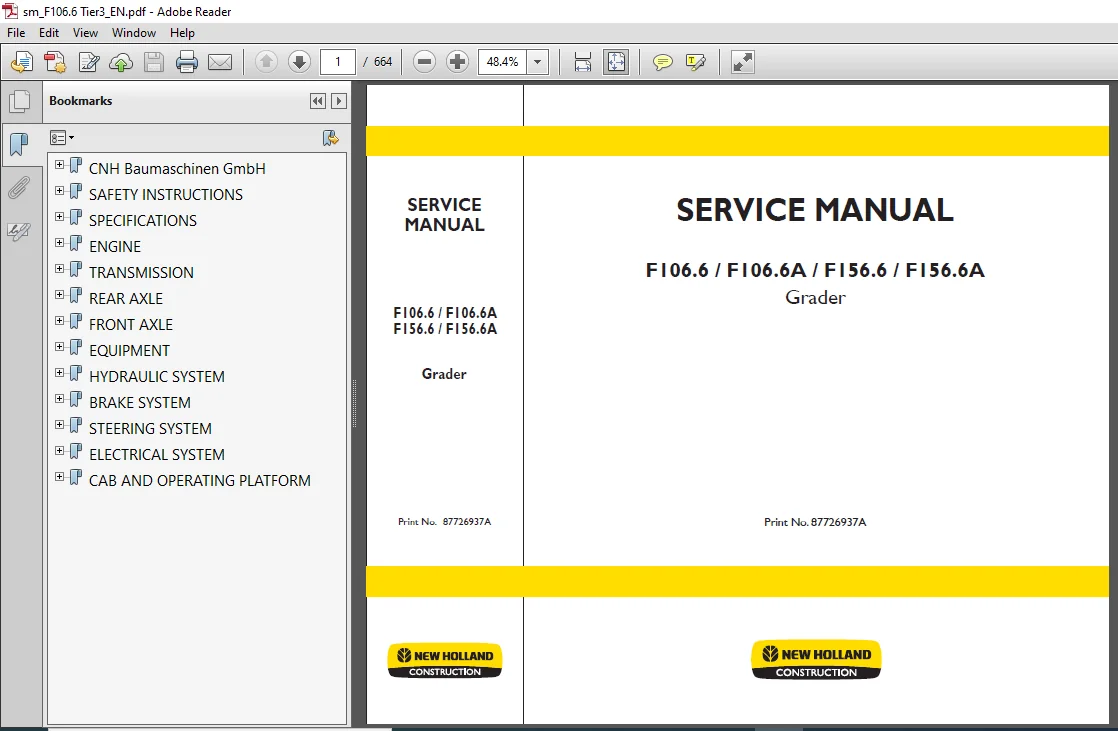
New Holland F106.6 F106.6A F156.6 F156.6A Grader Service Repair Manual
Print No. 87726937A
Description
New Holland F106.6 F106.6A F156.6 F156.6A Grader Service Repair Manual
FILE DETAILS:
New Holland F106.6 F106.6A F156.6 F156.6A Grader Service Repair Manual
Language : English
Pages : 664
Downloadable : YES
Format : PDF
Size : 23.6 MB
Print No. 87726937A
DESCRIPTION:
New Holland F106.6 F106.6A F156.6 F156.6A Grader Service Repair Manual
BASIC SAFETY INFORMATION:
This machine is constructed according to the recognized mechanical safety regulations, and using state-of-the-art technology. Nevertheless, when in operation, situations can occur that present serious or mortal dangers to the operator and third parties, or which could cause damage to the machine and other property. The machine should be used only if it is in proper operating condition, and only by operators who are aware of the dangers, know the safety procedures, and have read the operating instructions! The important notes are placed at the start of this section. Immediately repair any faults (or have them repaired) if these could have a prejudicial effect on safety.
1.2 Correct use:
This Grader is principally designed for:
• Creating a double course
• Clearing top soils
• Scarifying old road surfaces and hard ground
• Cutting embankments
• Clearing ice and snow
• Placing, spreading, mixing, and compressing materials.
The Grader can also be used in conjunction with other operating equipment for special applications. The Technical Data provide clear information on this subject. Proper use of the machine also means following the operating instructions and applying the inspection and maintenance conditions. Using the grader for any other purpose, for example:
- transporting personnel,
- as a working platform,
- towing or carrying loads without attaching the proper working attachments, is considered improper use.
Improper use of the machine can pose mortal danger to operating personnel or other persons, or may result in physical injuries, or may cause damage to property.
TABLE OF CONTENTS:
New Holland F106.6 F106.6A F156.6 F156.6A Grader Service Repair Manual
CNH Baumaschinen GmbH....................................................................................................................................................  0
	TO THE READER........................................................................................................................................................  3
	USE..................................................................................................................................................................  3
	REPAIR...............................................................................................................................................................  3
	FURTHER REFERENCE MATERIAL...........................................................................................................................................  3
	NOTES:...............................................................................................................................................................  4
SAFETY INSTRUCTIONS......................................................................................................................................................  7
	1 BASIC SAFETY INFORMATION........................................................................................................................................... 11
		1.1 Warning notes and symbols.................................................................................................................................... 11
		1.2 Correct use.................................................................................................................................................. 11
		1.3 Organizational procedures.................................................................................................................................... 12
		1.4 Personnel selection and qualifications - basic responsibilities.............................................................................................. 13
		1.5 Safety information for specific phases of operation.......................................................................................................... 14
		1.6 Special operations when using the machine, servicing and fault repair work as part of working procedure, waste disposal...................................... 15
		1.7 Notes on special types of hazard............................................................................................................................. 17
			1.7.1 Electrical energy...................................................................................................................................... 17
			1.7.2 Gas, dust, vapour, smoke............................................................................................................................... 17
			1.7.3 Hydraulic, pneumatic system............................................................................................................................ 17
			1.7.4 Noise.................................................................................................................................................. 17
			1.7.5 Oil, grease and other chemical substances.............................................................................................................. 17
		1.8 Transport, towing and restarting............................................................................................................................. 18
	2 WARNING AND INSTRUCTION PLATES..................................................................................................................................... 20
		2.1 Left side of vehicle......................................................................................................................................... 20
		2.2 Right side of vehicle........................................................................................................................................ 22
	3 OPERATION.......................................................................................................................................................... 25
		3.1 General Remarks.............................................................................................................................................. 25
		3.2 Fuelling..................................................................................................................................................... 27
		3.3 Fuelling system (optional)................................................................................................................................... 28
		3.4 Driving...................................................................................................................................................... 29
		3.5 Towing /recovery............................................................................................................................................. 31
			3.5.1 Towing devices......................................................................................................................................... 31
			3.5.2 Transport.............................................................................................................................................. 31
			3.5.3 Crane loading.......................................................................................................................................... 31
		3.6 Everyday operation........................................................................................................................................... 32
		3.7 Using the grader............................................................................................................................................. 32
		3.8 Working equipment............................................................................................................................................ 33
		3.9 SECURING THE MACHINE......................................................................................................................................... 34
	4 INSPECTION AND MAINTENANCE......................................................................................................................................... 35
		4.1 General information.......................................................................................................................................... 35
		4.2 Fuel system.................................................................................................................................................. 39
		4.3 Electrical system............................................................................................................................................ 40
		4.4 Power shift transmission..................................................................................................................................... 41
		4.5 Hydraulic system............................................................................................................................................. 41
		4.6 Brakes....................................................................................................................................................... 42
		4.7 Wheels and tyres............................................................................................................................................. 43
		4.8 Air conditioning system (optional)........................................................................................................................... 45
		4.9 Repair....................................................................................................................................................... 46
	5 PROTECTING ELECTRONIC UNITS WHEN WELDING........................................................................................................................... 48
		5.1 Disconnect the connectors of the electronic equipment........................................................................................................ 48
			5.1.1 Transmission control ‘EST37A’ (XA1) and front wheel drive control ‘FWD’ (XA8.1)........................................................................ 48
			5.1.2 AIC connections........................................................................................................................................ 49
			5.1.3 Engine control......................................................................................................................................... 49
			5.1.4 Cab connectors......................................................................................................................................... 49
			5.1.5 Alternator connector................................................................................................................................... 50
	6 VACUUM PUMP........................................................................................................................................................ 51
		6.1 General information.......................................................................................................................................... 51
		6.2 Package content.............................................................................................................................................. 51
		6.3 Vacuum pump connection....................................................................................................................................... 51
SPECIFICATIONS........................................................................................................................................................... 53
	1 Dimensions......................................................................................................................................................... 57
		1.1 Main dimensions F106.6 and F106.6 A.......................................................................................................................... 57
		1.2 Main dimensions F156.6 and F156.6 A.......................................................................................................................... 58
	2 Engine............................................................................................................................................................. 59
	3 Torque converter................................................................................................................................................... 59
	4 Transmission....................................................................................................................................................... 59
		4.1 Ratios....................................................................................................................................................... 60
	5 Tyre............................................................................................................................................................... 61
		5.1 Tyre types and pressures..................................................................................................................................... 61
			5.1.1 F106.6 / F106.6A....................................................................................................................................... 61
			5.1.2 F156.6 / F156.6A....................................................................................................................................... 61
			5.1.3 Wheel nut torques...................................................................................................................................... 61
	6 Rear axle.......................................................................................................................................................... 61
	7 Front axle......................................................................................................................................................... 61
	8 All-wheel drive.................................................................................................................................................... 62
	9 Hydraulic system................................................................................................................................................... 62
		9.1 Working equipment pump....................................................................................................................................... 62
		9.2 Pump for front wheel drive (for F106.6A / F156.6A only)...................................................................................................... 62
		9.3 Radial piston motor (F106.6A / F156.6A)...................................................................................................................... 62
		9.4 Motor for blade turntable.................................................................................................................................... 62
		9.5 Cylinder on F106.6 / F106.6A................................................................................................................................. 63
		9.6 Cylinder on F156.6 / F156.6A................................................................................................................................. 64
	10 Brake............................................................................................................................................................. 65
		10.1 Service brake............................................................................................................................................... 65
		10.2 Parking brake............................................................................................................................................... 65
	11 Steering.......................................................................................................................................................... 66
		11.1 Specifications for F106.6 / F106.6A......................................................................................................................... 66
		11.2 Specifications for F156.6 and F156.6A....................................................................................................................... 67
	12 Equipment......................................................................................................................................................... 68
		12.1 Centre equipment............................................................................................................................................ 68
		12.2 Front equipment (optional).................................................................................................................................. 69
		12.3 Rear equipment (optional)................................................................................................................................... 69
	13 Cab............................................................................................................................................................... 70
	14 Electrical system................................................................................................................................................. 70
	15 Operating fluids and lubricants................................................................................................................................... 71
		15.1 Fill quantities and specifications for F106.6 and F106.6A................................................................................................... 71
		15.2 Fill quantities and specifications for F156.6 and F156.6A................................................................................................... 72
ENGINE................................................................................................................................................................... 73
	1 General information................................................................................................................................................ 77
	2 Engine removal and installation.................................................................................................................................... 79
		2.1 Removal...................................................................................................................................................... 79
		2.2 Separate engine from transmission............................................................................................................................ 83
		2.3 Attach engine to transmission................................................................................................................................ 84
		2.4 Installation................................................................................................................................................. 85
TRANSMISSION............................................................................................................................................................. 89
	1 General Description................................................................................................................................................ 95
		1.1 Preface...................................................................................................................................................... 95
		1.2 Model plate.................................................................................................................................................. 95
		1.3 Technical data............................................................................................................................................... 96
		1.4 Composition.................................................................................................................................................. 96
		1.5 Important Notes..............................................................................................................................................100
	2 Version............................................................................................................................................................101
		2.1 Torque converter.............................................................................................................................................101
		2.2 Measurement plan and connections.............................................................................................................................103
		2.3 Power shift transmission.....................................................................................................................................105
		2.4 Hydraulic system.............................................................................................................................................107
		2.5 Electrical system............................................................................................................................................111
		2.6 Maintenance..................................................................................................................................................114
	3 ZF diagnostic system...............................................................................................................................................117
		3.1 General......................................................................................................................................................117
		3.2 Automatic detection of fill parameters.......................................................................................................................117
		3.3 Diagnosis....................................................................................................................................................121
		3.4 Diagnosis - inspection.......................................................................................................................................121
	4 Preface............................................................................................................................................................127
	5 General............................................................................................................................................................128
		5.1 International units of measurement...........................................................................................................................130
		5.2 Comparison table for units of measurement....................................................................................................................130
		5.3 Tightening torques for bolts.................................................................................................................................131
		5.4 Markings on model plate for ZF power shift transmission......................................................................................................132
		5.5 Structure of 6 WG-160........................................................................................................................................133
		5.6 Measurement plan and connections for 6 WG-160................................................................................................................135
		5.7 Notes on oil quality required................................................................................................................................137
	6 Tools..............................................................................................................................................................138
		6.1 Special tools for disassembly/assembly.......................................................................................................................138
		6.2 Commercially available tools for disassembly/assembly........................................................................................................146
	7 Disassembly of electro-hydraulic control unit and ZF fine filter (expendable filter)...............................................................................151
	8 Removal of inductive sensor, Hall sensor, breather, oil fill and drain screw.......................................................................................156
	9 Disassembly of engine connection, pressure oil pump, converter counter-pressure valve and temperature sensor (measuring point ‘63’ downstream of converter)........157
		9.1 Engine connection (direct mounting)..........................................................................................................................157
		9.2 Engine connection (separate mounting)........................................................................................................................158
		9.3 Pressure oil pump............................................................................................................................................160
		9.4 Converter counterpressure valve..............................................................................................................................162
	10 Disassembly of emergency steering pump............................................................................................................................163
		10.1 Version without emergency steering pump.....................................................................................................................163
		10.2 Version with emergency steering pump........................................................................................................................163
	11 Disassembly of output shafts......................................................................................................................................164
		11.1 Output flange on output side without parking brake..........................................................................................................164
		11.2 Output flange on output side with parking brake.............................................................................................................164
		11.3 Output flange converter side (without axle shut-off)........................................................................................................165
		11.4 Output flange converter side (with axle shut-off)...........................................................................................................166
	12 Disassembly of power take-offs....................................................................................................................................170
	13 Removal of drive shaft, output shaft and couplings................................................................................................................172
	14 Disassembly of couplings KV/KR/K1/K2/K3/K4, drive shaft and output shaft..........................................................................................175
		14.1 Coupling KV.................................................................................................................................................175
		14.2 Coupling KR.................................................................................................................................................179
		14.3 Coupling K1.................................................................................................................................................183
		14.4 Coupling K2.................................................................................................................................................187
		14.5 Coupling K3.................................................................................................................................................191
		14.6 Coupling K4.................................................................................................................................................195
		14.7 Drive shaft.................................................................................................................................................199
		14.8 Drive shaft.................................................................................................................................................200
	15 Assembly of couplings KV/KR/K1/K2/K3/K4, drive shaft and output shaft.............................................................................................201
		15.1 Coupling KV.................................................................................................................................................203
		15.2 Coupling KR.................................................................................................................................................209
		15.3 Coupling K1.................................................................................................................................................215
		15.4 Coupling K2.................................................................................................................................................220
		15.5 Coupling K3.................................................................................................................................................225
		15.6 Coupling K4.................................................................................................................................................230
		15.7 Drive shaft.................................................................................................................................................236
		15.8 Drive shaft.................................................................................................................................................238
	16 Installation of drive shaft, output shaft and couplings...........................................................................................................239
	17 Assembly of power take-offs.......................................................................................................................................246
	18 Assembly of output shafts.........................................................................................................................................248
		18.1 Output flange on output side without parking brake..........................................................................................................248
		18.2 Output flange on output side with parking brake.............................................................................................................249
		18.3 Output flange converter side (without axle shut-off)........................................................................................................251
		18.4 Output flange converter side (with axle shut-off)...........................................................................................................252
	19 Assembly of engine connection, pressure oil pump, converter counter-pressure valve and temperature sensor (measuring point ‘63’ downstream of Converter)..........259
		19.1 Converter counter-pressure valve............................................................................................................................259
		19.2 Pressure oil pump...........................................................................................................................................260
		19.3 Engine connection (direct mounting).........................................................................................................................263
		19.4 Engine connection (separate mounting).......................................................................................................................263
	20 Assembly of emergency steering pump...............................................................................................................................267
		20.1 Version without emergency steering pump.....................................................................................................................267
		20.2 Version with emergency steering pump........................................................................................................................267
	21 Assembly of inductive sensor, Hall sensor, breather, oil fill and drain screw.....................................................................................269
	22 Assembly of electro-hydraulic control unit with proportional valves...............................................................................................271
		22.1 Mounting the electric control unit..........................................................................................................................272
		22.2 WK valve....................................................................................................................................................279
		22.3 Mounting ZF fine filter (pressure filter)...................................................................................................................281
	23 Function description and maintenance instructions for spring-loaded calliper FSG 90...............................................................................283
		23.1 Structure and function......................................................................................................................................285
		23.2 Assembly and setting instruction............................................................................................................................286
			23.2.1 Brake installation....................................................................................................................................286
			23.2.2 Basic setting instruction.............................................................................................................................287
			23.2.3 Adjustment instruction................................................................................................................................287
		23.3 Parking brake emergency release.............................................................................................................................288
		23.4 Maintenance and repair work.................................................................................................................................289
			23.4.1 Maintenance and replacement of the brake lining carrier...............................................................................................289
			23.4.2 Replacing the seals...................................................................................................................................292
			23.4.3 General notes.........................................................................................................................................293
REAR AXLE................................................................................................................................................................295
	1 General information................................................................................................................................................299
		1.1 Using the manual.............................................................................................................................................299
		1.2 Conventions and terms used...................................................................................................................................299
		1.3 General disassembly/assembly instructions....................................................................................................................300
	2 General properties.................................................................................................................................................303
		2.1 Intended use.................................................................................................................................................303
		2.2 Product identification.......................................................................................................................................303
		2.3 General description..........................................................................................................................................304
	3 Tandem axle removal and installation...............................................................................................................................307
		3.1 Removal......................................................................................................................................................307
		3.2 Installation.................................................................................................................................................309
	4 Disassembly/assembly procedures....................................................................................................................................311
FRONT AXLE...............................................................................................................................................................313
	1 General information................................................................................................................................................317
		1.1 Using the manual.............................................................................................................................................317
		1.2 Conventions and terms used...................................................................................................................................317
		1.3 General disassembly/assembly instructions....................................................................................................................318
	2 General properties.................................................................................................................................................321
		2.1 Intended use.................................................................................................................................................321
		2.2 Product identification.......................................................................................................................................321
		2.3 General Description..........................................................................................................................................322
		2.4 Technical properties.........................................................................................................................................323
			2.4.1 Outside dimensions (in millimetres)....................................................................................................................323
			2.4.2 Sealants and adhesives.................................................................................................................................324
			2.4.3 Tightening torques.....................................................................................................................................325
			2.4.4 Special tools..........................................................................................................................................326
	3 All-wheel drive (F106.6A / F156.6A)................................................................................................................................327
		3.1 Technical data...............................................................................................................................................327
		3.2 Hydraulic system.............................................................................................................................................328
		3.3 Hydraulic diagram............................................................................................................................................330
		3.4 Components...................................................................................................................................................333
			3.4.1 Variable delivery pump.................................................................................................................................333
			3.4.2 Feed pump (integrated).................................................................................................................................334
			3.4.3 Valve VA ON/OFF........................................................................................................................................334
			3.4.4 Pressure reservoir.....................................................................................................................................334
			3.4.5 Flow divider...........................................................................................................................................335
			3.4.6 Wheel motors...........................................................................................................................................336
			3.4.7 Wheel motor actuation / chamber switchover valve.......................................................................................................336
	4 Front axle removal and installation................................................................................................................................337
		4.1 Removal......................................................................................................................................................337
		4.2 Installation.................................................................................................................................................340
	5 Disassembly/assembly procedures....................................................................................................................................343
		5.1 Hub and transmission (F106.6A and F156.6A)...................................................................................................................343
			5.1.1 Disassembly............................................................................................................................................343
			5.1.2 Assembly...............................................................................................................................................348
		5.2 Casing.......................................................................................................................................................353
			5.2.1 Disassembly............................................................................................................................................353
			5.2.2 Assembly...............................................................................................................................................360
		5.3 Steering cylinder............................................................................................................................................367
			5.3.1 Disassembly............................................................................................................................................367
			5.3.2 Assembly...............................................................................................................................................370
		5.4 Wheel camber cylinder........................................................................................................................................373
			5.4.1 Disassembly............................................................................................................................................373
			5.4.2 Assembly...............................................................................................................................................377
		5.5 Hydraulic system (F106.6A and F156.6A).......................................................................................................................381
			5.5.1 Disassembly............................................................................................................................................381
			5.5.2 Assembly...............................................................................................................................................388
	6 Setting and testing the front-wheel drive on F106.6A and F156.6.A..................................................................................................395
		6.1 Entering equipment data in the FWD control using the EDS tester..............................................................................................395
		6.2 Parameter setting for the FWD control........................................................................................................................397
		6.3 Individual settings of individual pump values according to pump characteristics (acceptance report)..........................................................400
		6.4 Setting individual pump characteristic values if there is no acceptance report...............................................................................402
		6.5 General function check.......................................................................................................................................403
		6.6 Testing with EDS tester and pressure measuring unit..........................................................................................................404
		6.7 Error codes sent by the FWD control..........................................................................................................................410
		6.8 Fault table..................................................................................................................................................410
EQUIPMENT................................................................................................................................................................413
	1 Centre equipment...................................................................................................................................................417
		1.1 Removal and installation.....................................................................................................................................417
			1.1.1 Removal................................................................................................................................................417
			1.1.2 Installation...........................................................................................................................................420
		1.2 Disassembly and assembly.....................................................................................................................................423
			1.2.1 Disassembly............................................................................................................................................423
			1.2.2 Assembly...............................................................................................................................................430
	2 Front equipment (optional), scraper blade or scarifier.............................................................................................................439
		2.1 Removal and installation.....................................................................................................................................439
			2.1.1 Removal................................................................................................................................................439
			2.1.2 Installation...........................................................................................................................................440
		2.2 Disassembly and assembly.....................................................................................................................................441
			2.2.1 Disassembly............................................................................................................................................441
			2.2.2 Assembly...............................................................................................................................................443
	3 Rear equipment (optional - scarifier)..............................................................................................................................444
		3.1 Removal and installation.....................................................................................................................................444
			3.1.1 Removal................................................................................................................................................444
			3.1.2 Installation...........................................................................................................................................445
		3.2 Disassembly and assembly.....................................................................................................................................446
			3.2.1 Disassembly............................................................................................................................................446
			3.2.2 Assembly...............................................................................................................................................447
	4 Front frame........................................................................................................................................................448
		4.1 Removal and installation.....................................................................................................................................448
			4.1.1 Removal................................................................................................................................................448
			4.1.2 Installation...........................................................................................................................................450
HYDRAULIC SYSTEM.........................................................................................................................................................453
	1 General............................................................................................................................................................457
		1.1 Intended use.................................................................................................................................................457
		1.2 Main components..............................................................................................................................................457
		1.3 Drive unit...................................................................................................................................................459
	2 Wiring diagrams for hydraulic system...............................................................................................................................460
		2.1 Hydraulic diagram F106.6.....................................................................................................................................460
		2.2 Hydraulic diagram F106.6A....................................................................................................................................462
		2.3 Hydraulic diagram F156.6.....................................................................................................................................464
		2.4 Hydraulic diagram F156.6A....................................................................................................................................466
		2.5 Hydraulic diagram - front drive..............................................................................................................................468
			2.5.1 Hydraulic diagram, front drive F106.6A.................................................................................................................469
			2.5.2 Hydraulic diagram, front drive F156.6A.................................................................................................................470
	3 Main functions.....................................................................................................................................................471
		3.1 General......................................................................................................................................................471
		3.2 Working equipment............................................................................................................................................471
		3.3 All-wheel drive (F106.6A and F156.6A)........................................................................................................................471
		3.4 Brake / steering.............................................................................................................................................471
		3.5 Oil cooling..................................................................................................................................................471
		3.6 Special functions............................................................................................................................................472
		3.7 Description of operation.....................................................................................................................................473
	4 Main components....................................................................................................................................................479
		4.1 Control block................................................................................................................................................479
		4.2 Double pump..................................................................................................................................................489
		4.3 Valve block..................................................................................................................................................492
		4.4 Hydraulic filter.............................................................................................................................................494
		4.5 Blade turntable hydraulic motor (orbit gear motor)...........................................................................................................495
		4.6 Blade lift cylinder, left and right..........................................................................................................................496
		4.7 Blade swing cylinder.........................................................................................................................................497
		4.8 Swing arm-detent pin cylinder................................................................................................................................498
		4.9 Blade movement cylinder......................................................................................................................................499
		4.10 Blade tilt cylinder (tilt angle adjustment cylinder)........................................................................................................500
		4.11 Joint cylinder..............................................................................................................................................501
		4.12 Rear scarifier cylinder (optional)..........................................................................................................................502
		4.13 Front scraper blade cylinder (optional).....................................................................................................................503
		4.14 Wheel camber cylinder.......................................................................................................................................504
		4.15 Steering cylinder...........................................................................................................................................505
		4.16 Radial piston motor.........................................................................................................................................506
		4.17 Rotary oil feed rotor.......................................................................................................................................507
BRAKE SYSTEM.............................................................................................................................................................509
	1 Description of brake system........................................................................................................................................513
		1.1 General......................................................................................................................................................513
		1.2 Service brake................................................................................................................................................514
		1.3 Parking brake................................................................................................................................................516
		1.4 Brake diagram................................................................................................................................................518
			1.4.1 Brake diagram, F106.6 and F106.6A......................................................................................................................519
			1.4.2 Brake diagram, F156.6 and F156.6A......................................................................................................................520
	2 Brake system components - function description.....................................................................................................................521
		2.1 Reservoir charge valve - shutoff valve.......................................................................................................................521
			2.1.1 Purpose................................................................................................................................................521
			2.1.2 Mode of operation......................................................................................................................................522
		2.2 Brake valve..................................................................................................................................................524
			2.2.1 Purpose................................................................................................................................................524
			2.2.2 Mode of operation......................................................................................................................................524
		2.3 Warning and signalling equipment.............................................................................................................................526
		2.4 Installation position........................................................................................................................................527
			2.4.1 Service brake..........................................................................................................................................527
			2.4.2 Parking brake..........................................................................................................................................528
	3 Troubleshooting....................................................................................................................................................529
STEERING SYSTEM..........................................................................................................................................................531
	1 System description.................................................................................................................................................535
		1.1 General......................................................................................................................................................535
		1.2 Technical data...............................................................................................................................................535
		1.3 Steering hydraulic system....................................................................................................................................536
		1.4 Emergency steering...........................................................................................................................................536
		1.5 Steering diagram.............................................................................................................................................538
			1.5.1 Steering diagram F106.6................................................................................................................................539
			1.5.2 Steering diagram F106.6A...............................................................................................................................540
			1.5.3 Steering diagram F156.6................................................................................................................................541
			1.5.4 Steering diagram F156.6A...............................................................................................................................542
	2 Steering system components - function description..................................................................................................................543
		2.1 Steering / emergency steering collector block................................................................................................................543
		2.2 Steering servo control.......................................................................................................................................544
		2.3 Cross-flushing...............................................................................................................................................547
		2.4 Safety valve 12 bar..........................................................................................................................................547
ELECTRICAL SYSTEM........................................................................................................................................................549
	1 Controls and indicators............................................................................................................................................553
		1.1 Instrument cluster warning indicator lamp....................................................................................................................553
		1.2 Front controls...............................................................................................................................................554
		1.3 Side console controls........................................................................................................................................555
		1.4 Fuses and diagnostic sockets.................................................................................................................................556
	2 Circuit diagram sheets.............................................................................................................................................559
		2.1 Contents of wiring diagram sheets............................................................................................................................559
		2.2 Sheet 3 - Fuse and relay box No. 1/2.........................................................................................................................560
		2.3 Sheet 4 - Fuse and relay box No. 2/3.........................................................................................................................561
		2.4 Sheet 5 - Fuse and relay box No. 3/4.........................................................................................................................562
		2.5 Sheet 6 - Fuse and relay box No. 4...........................................................................................................................563
		2.6 Sheet 7 - Power supply / starter motor.......................................................................................................................564
		2.7 Sheet 8 - Power supply EDC...................................................................................................................................565
		2.8 Sheet 9 - EDC, cod start.....................................................................................................................................566
		2.9 Sheet 10 - WIF, electronic accelerator pedal, start request..................................................................................................567
		2.10 Sheet 11 - CAN structure....................................................................................................................................568
		2.11 Sheet 12 - CAN structure....................................................................................................................................569
		2.12 Sheet 13 - Ground AIC_1, voltmeter, fill level sensor, hydraulic fluid/coolant temperature, brake alert pressure switch, parking brake switch / solenoid....570
		2.13 Sheet 14 - Power supply AIC_2, starter switch, start position, transmission neutralisation, brake light, buzzer.............................................571
		2.14 Sheet 15 - Floating position................................................................................................................................572
		2.15 Sheet 16 - Steering, emergency steering, fan control........................................................................................................573
		2.16 Sheet 17 - Power supply switch pad, connections to steering column switch, hydraulic fluid filter pressure switch, air filter pressure switch...............574
		2.17 Sheet 18 - Turn signal lamps................................................................................................................................575
		2.18 Sheet 19 - Illumination.....................................................................................................................................576
		2.19 Sheet 20 - Illumination.....................................................................................................................................577
		2.20 Sheet 21 - Illumination.....................................................................................................................................578
		2.21 Sheet 22 - Reversing relay, reversing lamp, reversing alert, socket, driver’s seat connector................................................................579
		2.22 Sheet 23 - Wiper/washer system (front)......................................................................................................................580
		2.23 Sheet 24 - Wiper/washer system (rear).......................................................................................................................581
		2.24 Sheet 25 - Rotating beacon, roof ventilator, blower/ heater, air conditioning...............................................................................582
		2.25 Sheet 26 - Transmission control EST-37A.....................................................................................................................583
		2.26 Sheet 27 - FWD wheel control................................................................................................................................584
		2.27 Sheet 28 - Working hydraulics rapid feed....................................................................................................................585
		2.28 Sheet 29 - Refuelling system................................................................................................................................586
		2.29 Sheet 30 - Interior light, radio............................................................................................................................587
		2.30 Sheet 31 - Spare fuses / relays.............................................................................................................................588
		2.31 Sheet 32 - Layout of relay and fuse box in side console (front view)........................................................................................589
		2.32 Sheet 33 - Layout of diagnostic sockets / 24VDC socket in side console (front view).........................................................................590
		2.33 Sheet 34 - Layout of switches / buttons on control console / steering column................................................................................591
		2.34 Sheet 35 - Layout of switches / buttons on side console.....................................................................................................592
		2.35 Sheet 36 - Layout of voltage distributors and ground bolts on side console (front view).....................................................................593
		2.36 Sheet 37 - Connector interface on side console (top view)...................................................................................................594
	3 Wiring harnesses...................................................................................................................................................595
		3.1 Cable set, rear frame (Sheet 1)..............................................................................................................................595
		3.2 Cable set, rear frame (Sheet 2)..............................................................................................................................596
		3.3 Cable set, engine - transmission (Sheet 1)...................................................................................................................597
		3.4 Cable set, engine - transmission (Sheet 2)...................................................................................................................598
		3.5 Cable set, engine - transmission (Sheet 3)...................................................................................................................599
		3.6 Cable set, engine - transmission (Sheet 4)...................................................................................................................600
		3.7 Cable set, engine - transmission (Sheet 5)...................................................................................................................601
		3.8 Cable set, engine - transmission (Sheet 6)...................................................................................................................602
		3.9 Cable set, control console (Sheet 1).........................................................................................................................603
		3.10 Cable set, control console (Sheet 2)........................................................................................................................604
		3.11 Cable set, control console (Sheet 3)........................................................................................................................605
		3.12 Cable set, control console (Sheet 4)........................................................................................................................606
		3.13 Cable set, control console (Sheet 5)........................................................................................................................607
		3.14 Cable set, control console (Sheet 6)........................................................................................................................608
		3.15 Cable set, driver’s cab floor (Sheet 1).....................................................................................................................609
		3.16 Cable set, driver’s cab floor (Sheet 2).....................................................................................................................610
		3.17 Cable set, driver’s cab floor (Sheet 3).....................................................................................................................611
		3.18 Cable set, driver’s cab floor (Sheet 4).....................................................................................................................612
		3.19 Cable set, driver’s cab floor (Sheet 5).....................................................................................................................613
		3.20 Cable set, driver’s cab floor (Sheet 6).....................................................................................................................614
		3.21 Cable set, driver’s cab floor (Sheet 7).....................................................................................................................615
		3.22 Cable set, driver’s cab floor (Sheet 8).....................................................................................................................616
		3.23 Cable set, side console (Sheet 1)...........................................................................................................................617
		3.24 Cable set, side console (Sheet 2)...........................................................................................................................618
		3.25 Cable set, side console (Sheet 3)...........................................................................................................................619
		3.26 Cable set, side console (Sheet 4)...........................................................................................................................620
		3.27 Cable set, side console (Sheet 5)...........................................................................................................................621
		3.28 Cable set, side console (Sheet 6)...........................................................................................................................622
		3.29 Cable set, side console (Sheet 7)...........................................................................................................................623
		3.30 Cable set, side console (Sheet 8)...........................................................................................................................624
		3.31 Cable set, side console (Sheet 9)...........................................................................................................................625
		3.32 Cable set, FWD control......................................................................................................................................626
		3.33 Cable set, floating position................................................................................................................................627
	4 Error codes........................................................................................................................................................628
		4.1 View error codes.............................................................................................................................................628
			4.1.1 Diagnosis screen.......................................................................................................................................628
			4.1.2 Error screen...........................................................................................................................................628
		4.2 Error code classification....................................................................................................................................629
			4.2.1 Vehicle error codes....................................................................................................................................630
			4.2.2 Engine fault codes.....................................................................................................................................632
		4.3 Transmission error code......................................................................................................................................644
		4.4 FWD control error code (all-wheel control)...................................................................................................................651
		4.5 Internal AIC error code......................................................................................................................................651
		4.6 Clear fault memory...........................................................................................................................................652
CAB AND OPERATING PLATFORM...............................................................................................................................................653
	1 Removal and installation of cab and operating platform.............................................................................................................657
		1.1 Cab removal..................................................................................................................................................657
		1.2 Removal of operating platform................................................................................................................................658
		1.3 Installation of operating platform...........................................................................................................................660
		1.4 Cab installation.............................................................................................................................................662
	2 Cab components.....................................................................................................................................................663
	3 Heating and ventilation............................................................................................................................................664
NEW HOLLAND F106.6 F106.6A F156.6 F156.6A GRADER SERVICE REPAIR MANUAL 87726937A – PDF DOWNLOAD:
IMAGES PREVIEW OF THE MANUAL:
PLEASE NOTE:
- This is the SAME MANUAL used by the dealerships to diagnose your vehicle
- No waiting for couriers / posts as this is a PDF manual and you can download it within 2 minutes time once you make the payment.
- Your payment is all safe and the delivery of the manual is INSTANT – You will be taken to the DOWNLOAD PAGE.
- So have no hesitations whatsoever and write to us about any queries you may have : heydownloadss @gmail.com