New Holland LB75.B LB90.B LB95.B LB110.B LB115.B 4WS Backhoe Loader Service Manual 6036702103 – PDF DOWNLOAD
Original price was: $89.95.$34.95Current price is: $34.95.
New Holland LB75.B LB90.B LB95.B LB110.B LB115.B 4WS Backhoe Loader Service Manual 6036702103 – PDF DOWNLOAD
Description
New Holland LB75.B LB90.B LB95.B LB110.B LB115.B 4WS Backhoe Loader Service Manual 6036702103 – PDF DOWNLOAD
IMAGES PREVIEW OF THE MANUAL:
DESCRIPTION:
New Holland LB75.B LB90.B LB95.B LB110.B LB115.B 4WS Backhoe Loader Service Manual 6036702103 – PDF DOWNLOAD
Chapter 1 – General Instructions:
IMPORTANT NOTICE:
- All maintenance and repair operations described in this manual should be carried out exclusively by authorised
workshops. All instructions detailed should be carefully observed and special equipment indicated should be
used if necessary. - Everyone who carries out service operations described without carefully observing these prescriptions will be
directly responsible of deriving damages.
SHIMMING:
At each adjustment, select adjusting shims, measure them individually using a micrometer and then sum up
recorded values. Do not rely on measuring the whole shimming set, which may be incorrect, or on rated value
indicated for each shim.
ROTATING SHAFT SEALS:
To correctly install rotating shaft seals, observe the following instructions:
– Let the seal soak into the same oil as it will seal for at least half an hour before mounting;
– Thoroughly clean the shaft and ensure that the shaft working surface is not damaged;
– Place the sealing lip towards the fluid. In case of a hydrodynamic lip, consider the shaft rotation direction and
orient grooves in order that they deviate the fluid towards the inner side of the seal;
– Coat the sealing lip with a thin layer of lubricant (oil rather than grease) and fill with grease the gap between
the sealing lip and the dust lip of double lip seals;
– Insert the seal into its seat and press it down using a flat punch. Do no tap the seal with a hammer or a drift;
– Take care to insert the seal perpendicularly to its seat while you are pressing it. Once the seal is settled,
ensure that it contacts the thrust element if required.;
– To prevent damaging the sealing lip against the shaft, place a suitable protection during installation.
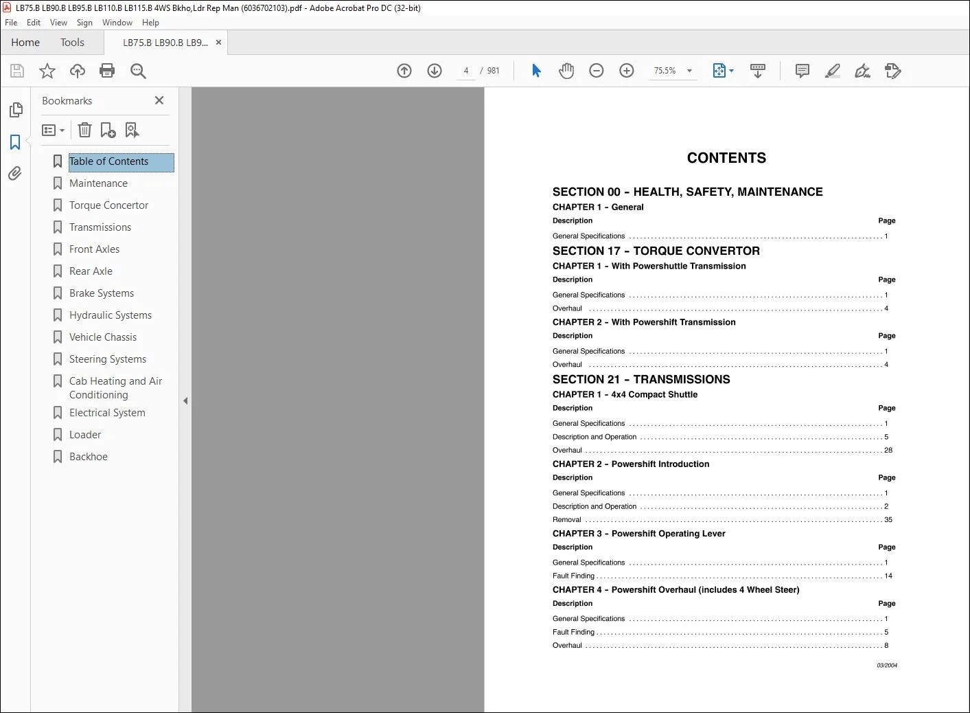
TABLE OF CONTENTS:
New Holland LB75.B LB90.B LB95.B LB110.B LB115.B 4WS Backhoe Loader Service Manual 6036702103 – PDF DOWNLOAD
SECTION 00 – HEALTH, SAFETY, MAINTENANCE
CHAPTER 1 – General
Description Page
General Specifications 1
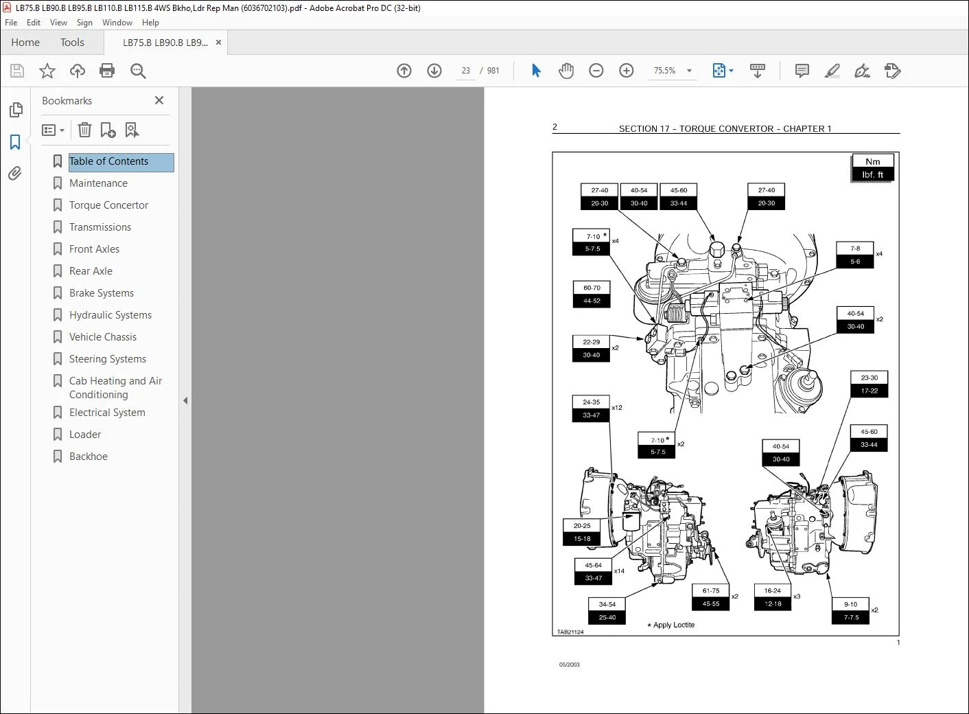
SECTION 17 – TORQUE CONVERTOR
CHAPTER 1 – With Powershuttle Transmission
Description Page
General Specifications 1
Overhaul 4
CHAPTER 2 – With Powershift Transmission
Description Page
General Specifications 1
Overhaul 4
SECTION 21 – TRANSMISSIONS
CHAPTER 1 – 4×4 Compact Shuttle
Description Page
General Specifications 1
Description and Operation 5
Overhaul 28
CHAPTER 2 – Powershift Introduction
Description Page
General Specifications 1
Description and Operation 2
Removal 35
CHAPTER 3 – Powershift Operating Lever
Description Page
General Specifications 1
Fault Finding 14
CHAPTER 4 – Powershift Overhaul (includes 4 Wheel Steer)
Description Page
General Specifications 1
Fault Finding 5
Overhaul 8
03/2004
2 CONTENTS
SECTION 25 – FRONT AXLES
CHAPTER 1 – Front Axle for 2 and 4 Wheel Drive Only
Description Page
General Specifications 1
Overhaul 1 O
CHAPTER 2 – Front Axle for 4 Wheel Steer Only
Description Page
General Specifications 1
Overhaul 3
CHAPTER 3 – Front Axle
Description Page
Identification 1
Overhaul 4
CHAPTER 7 – Front Axle
Description Page
Identification 1
Overhaul 4
CHAPTER 10- Front Axle
Identification 1
SECTION 27 – REAR AXLES
CHAPTER 1 – Rear Axle with Foot Operated Diff Lock for 2 and 4 Wheel Drive Only
Description Page
General Specifications 1
Overhaul 6
CHAPTER 2 – Rear Axle with Electrically Operated Diff Lock for 2 and 4 Wheel Drive
Only
Description Page
General Specifications 1
Overhaul 8
CHAPTER 3 – Rear Axle for 4 Wheel Steer Only
Description Page
General Specifications 1
Overhaul 2
CHAPTER 4 – Rear Axle
Description Page
Identification 1
SECTION 33 – BRAKE SYSTEMS
CHAPTER 1 – Brakes for 2 and 4 Wheel Drive Only
Description Page
General Specifications 1
Overhaul 8
CHAPTER 2 – Brakes for 4 Wheel Steer Only
Description Page
General Specifications 1
Overhaul 5
SECTION 35 – HYDRAULIC SYSTEMS
CHAPTER 1 – Hydraulic Circuits and Components for HUSCO Only
Description Page
General Specifications 2
Hydraulic Valve Spool Seals 15
Stabliliser and Extendible Dipper Control Valves 21
Loader Control Valve 33
Backhoe Control Valve 49
CHAPTER 2 – Fault Finding, Pressure and Flow Testing for HUSCO Only
Description Page
General Specifications 2
Fault Finding 6
Pressure Testing 11
Flow Testing (Pump Performance Test) 21
CHAPTER 3 – Hydraulic Circuits and Components for REXROTH
Description Page
General Specifications 1
Description and Operation 5
Hydraulic Circuits 10
CHAPTER 4 – Fault Finding, Pressure and Flow Testing for REXROTH Only
Description Page
Specifications 1
Preliminary Checks 2
Fault Finding Charts 3
Pressure Testing 7
Steering Stndby 7
Steering Circuit Relief Valve 7
System Pressure Relief Valve 8
Loader Bucket Relief Valve (Piston End) 9
Extendible Dipper Relief Valve (Piston End) 8
Swing System Relief Valve 9
Dipperstick Bucket and Boom Relief Valves 9
Flow Testing (Pump Performance Test) 10
CHAPTER 5 – Control Valves for REXROTH with Mechanical or Hydraulic Control
Description Page
General Specifications 1
Loader Control Valve Overhaul 2
Backhoe Control Valve Overhaul 3
Control Valve Disassembly 4
Control Valve Section Disassembly 8
CHAPTER 6 – Swing System and Hydraulic Cylinders
Description Page
General Specifications 1
Swing System Description and Operation 3
Hydraulic Cylinders Description and Operation 6
Backhoe and Loader Cylinders – Removal and Installation 9
Backhoe and Loader Cylinder Overhaul 18
Swing Cylinder Removal and Overhaul 22
CHAPTER 7 – Hydraulic Pump
General Specifications 1
Tightening torques 1
Description and Operation 2
Pump Overhaul 5
Flow Divider Overhaul 7
Rear Pump Overhaul 8
Front Pump Overhaul 11
CHAPTER 8 – Rexroth Control Blocks
Description Page
General Specifications 1
Tightening torques 1
Exploded Wiew of the Lever 2
Overhaul of the Control Block 5
SECTION 39 – VEHICLE CHASSIS
CHAPTER 1 – CHASSIS COMPONENTS
Description Page
General Specifications 1
Overhaul 6
SECTION 41 – STEERING SYSTEMS
CHAPTER 1 – Steering for 2 and 4 Wheel Drive Only
Description Page
General Specifications 1
Fault Finding 7
Overhaul 8
CHAPTER 2 – Steering for 4 Wheel Steer Only
Description Page
General Specifications 1
Fault Finding 7
Overhaul 1 O
SECTION 50 – CAB HEATING AND AIR CONDITIONING
CHAPTER 1 – Cab Heating
Description Page
General Specifications 1
Fault Finding 5
Overhaul 6
CHAPTER 2 – Cab Air Conditioning
Description Page
General Specifications 1
Description & operation 5
Fault Finding 16
Overhaul 38
SECTION 55 – ELECTRICAL SYSTEM
CHAPTER 1 – System General
Description Page
Electrical Equipment Specifications 1
Tempory wiring harness repair 2
Electrical System General Fault Finding 3
CHAPTER 2 1- Powershuttle Wiring Diagrams (N/A and Europeen Model)
Description Page
Fuses and Relays 2
Components 3
Connector 4
Wiring Diagrams (N/A and Europeen Model) 6
Connectors (Details) 18
CHAPTER 2 2- Powershift Wiring Diagrams (N/A and Europeen Model)
Description Page
Fuses and Relays 2
Components 3
Connector 4
Wiring Diagrams (N/A and Europeen Model) 6
Connectors (Details) 18
CHAPTER 2 3- Powershift 4 WS Wiring Diagrams (N/A and Europeen Model)
Description Page
Fuses and Relays 2
03/2004
CONTENTS
Components 3
Connector 4
Wiring Diagrams (N/A and Eurpeen Model 6
Connectors (Details) 18
CHAPTER 2 4- ROPS Wiring Diagrams (N/A and Europeen Model)
Description Page
Fuses and Relays 2
Components 3
Connector 4
Wiring Diagrams (N/A and Europeen Model) 6
Connectors (Details) 19
CHAPTER 3 – Starter Motor 2, 7kW
Description Page
General Specifications 1
Fault Finding 3
Exploded Wiew of the Starter 6HA
CHAPTER 4 – Alternator 90A
Description Page
General Specifications 1
Fault Finding 4
Exploded Wiew of the Alternator 6
CHAPTER 5 – Battery
Description Page
General Specifications 1
Removal and Installation 2
Battery Maintenance and Tests 3
Battery Charging 4
Common Causes of Battery Failure 6
CHAPTER 6 – Service Diagnostics, Calibration and Immobiliser
Description Page
Service Indicators 1
Alarms and Diagnostics Signalling 2
Calibration of speedometer 4
CHAPTER 7 – Component Testing
General Introduction 2
Component Testing 3
Component Earth Points 4
SECTION 82 – LOADER
CHAPTER 1 – Loader Frame, Controls and Buckets for 2 and 4 Wheel Drive Only
Tightening Torques and Special Tools 1
General Specifications 2
Description and Operation 5
Overhaul – Loader Controls 6
CHAPTER 2 – Loader Frame, Controls and Buckets for 4 Wheel Steer Only
General Specifications 2
Description and Operation 4
Overhaul – Loader Controls 5
SECTION 84 – BACKHOE
CHAPTER 1 – Backhoe, Boom and Dipperstick assembly
Description Page
General Specifications 1
Description and Operation 7
Backhoe Control Linkage Overhaul 15
Component Removal 18
Dipperstick 21
Extendible Dipperstick Overhaul 27
Contact us: [email protected]
PLEASE NOTE:
- This is the same manual used by the DEALERSHIPS to SERVICE your vehicle.
- The manual can be all yours – Once payment is complete, you will be taken to the download page from where you can download the manual. All in 2-5 minutes time!!
- Need any other service / repair / parts manual, please feel free to contact us at heydownloadss @gmail.com . We may surprise you with a nice offer
S.V