New Holland LB90.B LB95.B LB110.B LB115.B Tractor Backhoe Loader Workshop Manual 60413547 – PDF DOWNLOAD
Original price was: $89.00.$38.95Current price is: $38.95.
New Holland LB90.B LB95.B LB110.B LB115.B Tractor Backhoe Loader Workshop Manual
Part No: 60413547
Description
New Holland LB90.B LB95.B LB110.B LB115.B Tractor Backhoe Loader Workshop Manual
FILE DETAILS:
New Holland LB90.B LB95.B LB110.B LB115.B Tractor Backhoe Loader Workshop Manual
Size: 113 MB
Format: PDF
Language: English
Number of Pages: 1083 pages
Brand: New Holland
Type of document: Workshop Manual
Model: LB110.B, LB115.B, LB90.B, LB95.B
Part No: 60413547
DESCRIPTION:
New Holland LB90.B LB95.B LB110.B LB115.B Tractor Backhoe Loader Workshop Manual
SAFETY RULES:
Carefully follow specified repair and maintenance procedures. Do not wear rings, wristwatches, jewels, unbuttoned or flapping clothing such as ties, torn clothes, scarves, open jackets or shirts with open ips which could get hold into moving parts. We advise to use approved safety clothing such as anti-slipping footwear, gloves, safety goggles, helmets, etc. Never carry out any repair on the machine if someone is sitting on the operator’s seat, except if they are certified operators to assist in the operation to be carried out. Never operate the machine or use attachments from a place other than sitting at the operator’s seat.
- Never carry out any operation on the machine when the engine is running, except when specifically indicated. Stop the engine and ensure that all pressure is relieved from hydraulic circuits before removing caps, covers, valves, etc. All repair and maintenance operations should be carried out with the greatest care and attention. Service stairs and platforms used in a workshop or in the field should be built in compliance with the safety rules in force. Disconnect the batteries and label all controls to warn that the Machine is being serviced. Block the machine and all equipment which should be raised.
- Never check or fill fuel tanks and accumulator batteries, nor use starting liquid if you are smoking or near open flames as such fluids are flammable. Brakes are inoperative when they are manually released for maintenance purposes. In such cases, the machine should be kept constantly under control using blocks or similar devices. The fuel filling gun should remain always in contact with the filler neck.
- Maintain this contact until the fuel stops flowing into the tank to avoid possible sparks due to static electricity buildup. Use exclusively specified towing points for towing the machine. Connect parts carefully. Ensure that foreseen pins and/or locks are steadily fixed before applying traction. Do not stop near towing bars, cables or chains working under load. To transfer a failed machine, use a trailer or a low loading platform trolley if available. To load and unload the machine from the transportation mean, select a flat area providing a firm support to the trailer or truck wheels.
- Firmly tie the machine to the truck or trailer platform and block wheels as required by the forwarder. For electrical heaters, battery-chargers and similar equipment use exclusive auxiliary power supplies with a efficient ground to avoid electrical shock haard. Always use lifting equipment and similar of appropriate capacity to lift or move heavy components. Pay special attention to bystanders. Never pour gasoline or diesel oil into open, wide and low containers.
- Never use gasoline, diesel oil or other flammable liquids as cleaning agents. Use non-flammable non-toxic proprietary solvents. Wear protection goggles with side guards when cleaning parts using compressed air. Do not exceed a pressure of 2.1 bar, in accordance with local regulations. Do not run the engine in a closed building without proper ventilation. Do not smoke, use open flames, cause sparks in the nearby area when filling fuel or handling highly flammable liquids. Do not use flames as light sources when working on a machine or checking for leaks. Move with caution when working under a Machine, and also on or near a Machine.
- Wear proper safety accessories: helmets, goggles and special footwear. During checks which should be carried out with the engine running, ask an assistant to sit at the operator’s seat and keep the service technician under visual control at any moment. In case of operations outside the workshop, drive the machine to a flat area and block it. If working on an incline cannot be avoided, first block the Machine carefully.
- Move it to a flat area as soon as possible with a certain extent of safety. Ruined or plied cables and chains are unreliable. Do not use them for lifting or trailing. Always handle them wearing gloves of proper thickness. Chains should always be safely fastened. Ensure that fastening device is strong enough to hold the load foreseen. No persons should stop near the fastening point, trailing chains or cables. The working area should be always kept CLEAN and DRY. Immediately clean any spillage of water or oil.
- Do not pile up grease or oil soaked rags, as they constitute a great fire haard. Always place them into a metal container. Before starting the Machine or its attachments, check, adjust and block the operator’s seat. Also ensure that there are no persons within the Machine or attachment operating range. Do not keep in your pockets any object which might fall unobserved into the Machine’s inner compartments.
TABLE OF CONTENTS:
New Holland LB90.B LB95.B LB110.B LB115.B Tractor Backhoe Loader Workshop Manual
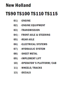
SECTION 00 – SAFETY PRECAUTIONS
SECTION 01 – MAINTENANCE
SECTION 02 – TECHNICAL SPECIFICATIONS
1 MODELS 3
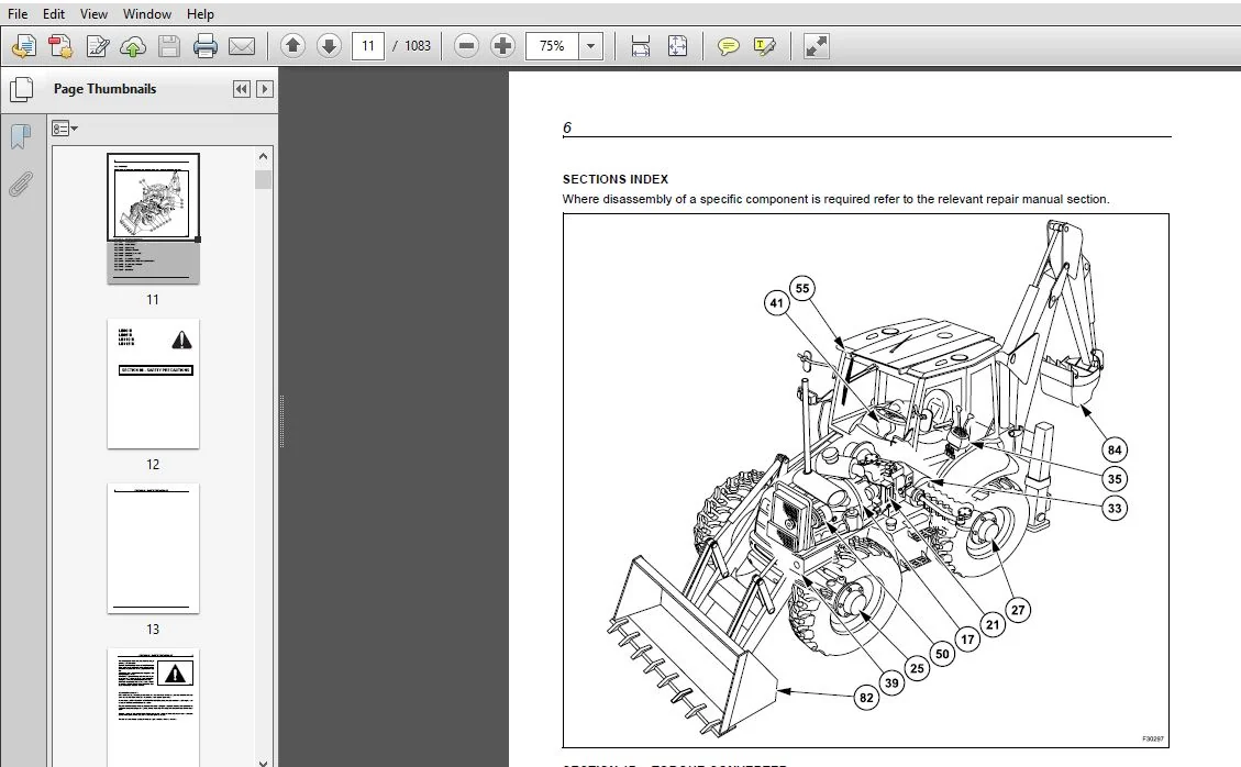
2 IDENTIFICATION OF MAIN COMPONENTS 4
3 TECHNICAL SPECIFICATIONS 5
4 LOADER ATTACHMENT DIMENSIONS AND PERFORMANCE 9
5 BACKHOE ATTACHMENT DIMENSIONS AND PERFORMANCE 13
6 LIFTING CAPACITIES 18
7 LOADER BUCKET WITH FORKS DIMENSIONS AND PERFORMANCE 23
8 FLUID AND LUBRICANT CAPACITIES AND SPECIFICATIONS 24
SECTION 17 – TORQUE CONVERTERS
1 POWERSHUTTLE TORQUE CONVERTER 3
11 DESCRIPTION AND OPERATION 3
12 TECHNICAL SPECIFICATIONS 4
13 OVERHAUL 4
14 INSPECTION 4
15 DISASSEMBLY AND ASSEMBLY 5
16 STALL TEST 5
17 FAULT FINDING 6
2 POWERSHIFT TORQUE CONVERTER 7
21 DESCRIPTION AND OPERATION 7
22 TECHNICAL SPECIFICATIONS 8
23 OVERHAUL 8
24 INSPECTION 9
25 DISASSEMBLY AND ASSEMBLY 9
26 STALL TEST 11
27 FAULT FINDING 12
SECTION 21 – TRANSMISSION
1 POWERSHUTTLE TRANSMISSION “TURNER MODEL COM-T4-2025” 3
11 TECHNICAL SPECIFICATIONS 3
12 TIGHTENING TORQUES 5
13 TRANSMISSION CONTROLS 6
14 LUBRICATION 11
15 TRANSMISSION OIL FLOW AND SUPPLY 12
16 TRANSMISSION HYDRAULIC VALVES AND PRESSURE TEST POINTS 18
17 TRANSMISSION POWER FLOW 19
18 TRANSMISSION 2WD COMPONENTS 23
19 TRANSMISSION 4WD COMPONENTS 26
110 TRANSMISSION REMOVAL 31
111 DISASSEMBLY AND ASSEMBLY 32
112 FAULT FINDING 90
113 SPECIAL TOOLS 93
2 POWERSHIFT TRANSMISSION “DANA T16000” 94
21 TECHNICAL SPECIFICATIONS 94
22 TRANSMISSION CONTROLS 95
23 LUBRICATION 105
24 PRESSURE SPECIFICATIONS AND CHECK POINTS 106
25 TRANSMISSION COOLER 108
26 TRANSMISSION HYDRAULIC DIAGRAM 109
27 OPERATION 110
28 POWER FLOWS 117
29 GEAR AND CLUTCH LAY OUT 132
210 TRANSMISSION REMOVAL AND INSTALLATION 133
211 TRANSMISSION COMPONENTS 137
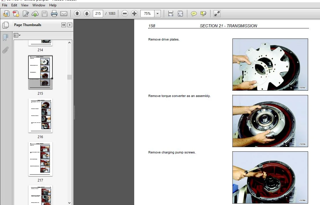
212 DISASSEMBLY AND ASSEMBLY 155
213 SPECIAL TOOLS 264
214 FAULT FINDING 265
215 FAULT FINDING 267
SECTION 25 – FRONT AXLES
1 FRONT AXLE 2WD “CARRARO” 3
11 TECHNICAL SPECIFICATIONS 3
12 DISASSEMBLY AND ASSEMBLY 5
13 FAULT FINDING 23
2 FRONT AXLE 4WD “CARRARO” 25
21 TECHNICAL SPECIFICATIONS 25
22 DISASSEMBLY AND ASSEMBLY 31
23 FAULT FINDING 77
3 FRONT AXLE 4WS “CARRARO” 80
31 TECHNICAL SPECIFICATIONS 80
32 DISASSEMBLY AND ASSEMBLY 84
33 FAULT FINDING 137
4 SPECIAL TOOLS 140
SECTION 27 – REAR AXLE
1 REAR AXLE 2WS 3
11 DESCRIPTION AND OPERATION 3
12 TECHNICAL SPECIFICATIONS 6
13 DISASSEMBLY AND ASSEMBLY 8
14 FAULT FINDING 27
2 REAR AXLE 4WS “CARRARO” 28
21 TECHNICAL SPECIFICATIONS 28
22 DISASSEMBLY AND ASSEMBLY 32
23 FAULT FINDING 81
3 SPECIAL TOOLS 84
SECTION 33 – BRAKES SYSTEM
1 TECHNICAL SPECIFICATIONS 3
2 HAND BRAKE 6
3
21 HAND BRAKE ADJUSTMENT 7
3 BRAKE CYLINDERS 8
4 OIL BRAKE TANK 13
5 BLEEDING PROCEDURE 13
SECTION 35 – HYDRAULIC SYSTEM
1 HYDRAULIC DIAGRAMS 3
11 HYDRAULIC DIAGRAM – 2WS CENTRE PIVOT MECHANICAL MODELS 3
12 HYDRAULIC DIAGRAM – 2WS SIDESHIFT MECHANICAL MODELS 5
13 HYDRAULIC DIAGRAM – 2WS CENTRE PIVOT PILOT MODELS 7
14 HYDRAULIC DIAGRAM – 2WS SIDESHIFT PILOT MODELS 10
15 HYDRAULIC DIAGRAM – 4WS CENTRE PIVOT MECHANICAL MODELS 13
16 HYDRAULIC DIAGRAM – 4WS SIDESHIFT MECHANICAL MODELS 15
17 HYDRAULIC DIAGRAM – 4WS CENTRE PIVOT PILOT MODELS 17
18 HYDRAULIC DIAGRAM – 4WS SIDESHIFT PILOT MODEL 20
2 HYDRAULIC PUMP 23
21 DESCRIPTION AND OPERATION 23
22 TECHNICAL SPECIFICATIONS 24
23 LOAD SENSING VALVE 26
24 REMOVAL 28
25 COMPONENTS 29
26 DISASSEMBLY AND ASSEMBLY 30
3 CONTROL VALVES 34
31 CONTROL VALVES “HUSCO” (LB110B CENTRE PIVOT MECHANICAL MODELS) 34
32 CONTROL VALVES “REXROTH” (MECHANICAL MODELS) 71
33 CONTROL VALVES “REXROTH” (PILOT MODELS) 87
4 HYDRAULIC SWING SYSTEM 111
41 DESCRIPTION AND OPERATION 111
42 HYDRAULIC OIL FLOW 112
43 PRECISION SWING CONTROL 114
5 HYDRAULIC CYLINDERS 117
51 LOADER CYLINDER 118
52 LOADER BUCKET CYLINDER 124
53 4X1 BUCKET CYLINDER 130
54 BACKHOE BOOM CYLINDER 133
55 BACKHOE DIPPER CYLINDER 137
56 BACKHOE BUCKET CYLINDER 141
57 SHORT AND LONG TELESCOPIC CYLINDER 145
58 STABILIZER CYLINDER (CENTRE PIVOT MODELS) 149
59 STABILIZER CYLINDER (SIDESHIFT MODELS) 153
510 SWING CYLINDER 157
511 BACKHOE SIDESHIFT LOCKING CYLINDER (SIDESHIFT) 161
512 SPECIAL TOOLS 163
6 CONTROL LEVERS 164
61 TECHNICAL SPECIFICATIONS 164
62 DESCRIPTION AND OPERATION 165
63 DISASSEMBLY AND ASSEMBLY 168
64 CONTROL LEVER VALVE 171
7 FAULT FINDING AND FLOW TESTING 174
71 PRELIMINARY CHECKS 174
4
72 FAULT FINDING (WITH “HUSCO” CONTROL VALVES) – LB110B CENTRE PIVOT 175
73 PRESSURE TESTING (WITH “HUSCO” CONTROL VALVES) – LB110B CENTRE PIVOT 180
74 FAULT FINDING (WITH “REXROTH” CONTROL VALVES) 188
75 PRESSURE TESTING (WITH “REXROTH” CONTROL VALVES) 192
SECTION 39 – CHASSIS
1 DESCRIPTION AND OPERATION 3
2 REMOVAL AND INSTALLATION COMPONENTS 6
21 COMPONENTS WITHIN THE CHASSIS 6
22 COMPONENTS BELOW THE CHASSIS 7
23 COMPONENTS ATTACHED OUTSIDE THE CHASSIS 9
24 COMPONENTS ATTACHED ABOVE THE CHASSIS 10
25 TIGHTENING TORQUES 12
SECTION 41 – STEERING SYSTEM
1 STEERING SYSTEM 2WS 4
2 STEERING SYSTEM 4WS 7
3 POWER STEERING 12
31 TECHNICAL SPECIFICATIONS 13
32 COMPONENTS 15
33 DISASSEMBLY AND ASSEMBLY 16
34 SPECIAL TOOLS 33
35 FAULT FINDING 33
SECTION 50 – CAB HEATING AND AIR CONDITIONING
1 TECHNICAL SPECIFICATIONS 3
2 CAB HEATING 5
21 DESCRIPTION AND OPERATION 5
3 AIR CONDITIONING 12
31 PRINCIPALS OF AIR CONDITIONING 12
32 SAFETY PRECAUTIONS 16
33 DESCRIPTION AND OPERATION 17
34 FAULT FINDING AND TESTING 25
35 FLUSHING THE SYSTEM 43
36 EVACUATING THE SYSTEM 45
37 CHARGING THE SYSTEM 46
38 COMPONENTS OVERHAUL 47
39 COMPRESSOR 51
310 SPECIAL TOOLS 65
SECTION 55 – ELECTRICAL SYSTEM
1 GENERALITIES 3
11 TEMPORARY WIRING HARNESS REPAIR 3
12 FAULT FINDING 4
2 ELECTRICAL DIAGRAMS 5
21 ELECTRICAL DIAGRAMS – POWERSHUTTLE CAB 5
22 ELECTRICAL DIAGRAMS – POWERSHIFT CAB 24
23 ELECTRICAL DIAGRAMS – 4WS 43
24 ELECTRICAL DIAGRAMS – ROPS 62
5
3 CONTROLS AND INSTRUMENTS 77
31 FRONT INSTRUMENT PANEL 77
32 SIDE INSTRUMENT PANEL 79
33 DIAGNOSTIC SIGNALING 81
34 CALIBRATION OF SPEEDOMETER 83
35 IMMOBILISER CIRCUIT 84
4 STARTING SYSTEM 85
41 DESCRIPTION AND OPERATION 85
42 FAULT FINDING 86
43 STARTER MOTOR 89
5 ALTERNATOR 95
51 TECHNICAL SPECIFICATIONS 95
52 DESCRIPTION AND OPERATION 95
53 COMPONENTS 97
54 REMOVAL 98
55 PRELIMINARY CHECK AND TESTS 99
56 FAULT FINDING 108
6 BATTERY 109
61 TECHNICAL SPECIFICATIONS 109
62 DESCRIPTION AND OPERATION 109
63 BATTERY REPLACEMENT 110
64 MAINTENANCE 112
65 TESTS 114
66 CONNECTING A BOOSTER BATTERY 116
67 BATTERY MASTER SWITCH (optional LB90B – LB95B) 116
7 COMPONENT TESTING 117
71 GENERAL INTRODUCTION 117
72 COMPONENT TESTING 118
73 GROUND POINTS 118
SECTION 82 – LOADER
1 LOADER ATTACHMENT CONTROLS 4
2 LOADER BUCKET SELF LEVELING 7
3 LOADER ATTACHMENT SAFETY STRUT 10
4 LOADER BUCKET REMOVAL 12
5 LOADER REMOVAL (2WS) 15
6 LOADER REMOVAL (4WS) 17
SECTION 84 – BACKHOE
1 DESCRIPTION AND OPERATION 3
2 BACKHOE ATTACHMENT MECHANICAL CONTROL VERSION 6
3 BACKHOE ATTACHMENT PILOT CONTROL VERSION 12
4 REMOVAL AND INSTALLATION 14
5 TELESCOPIC DIPPER REVISION 24
NEW HOLLAND LB90.B LB95.B LB110.B LB115.B TRACTOR BACKHOE LOADER WORKSHOP MANUAL 60413547 – PDF DOWNLOAD:
IMAGES PREVIEW OF THE MANUAL:
PLEASE NOTE:
- This is the SAME MANUAL used by the dealerships to diagnose your vehicle
- No waiting for couriers / posts as this is a PDF manual and you can download it within 2 minutes time once you make the payment.
- Your payment is all safe and the delivery of the manual is INSTANT – You will be taken to the DOWNLOAD PAGE.
- So have no hesitations whatsoever and write to us about any queries you may have : heydownloadss @gmail.com