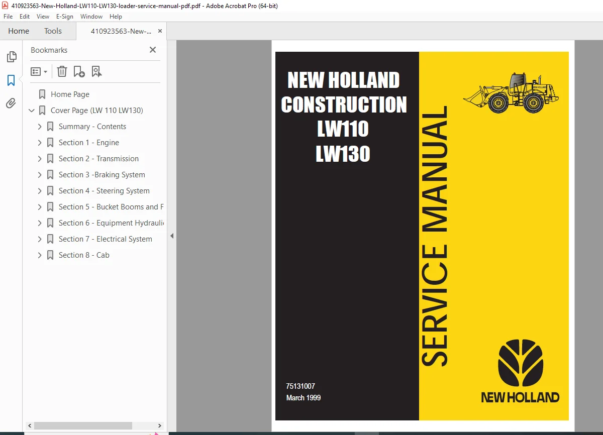
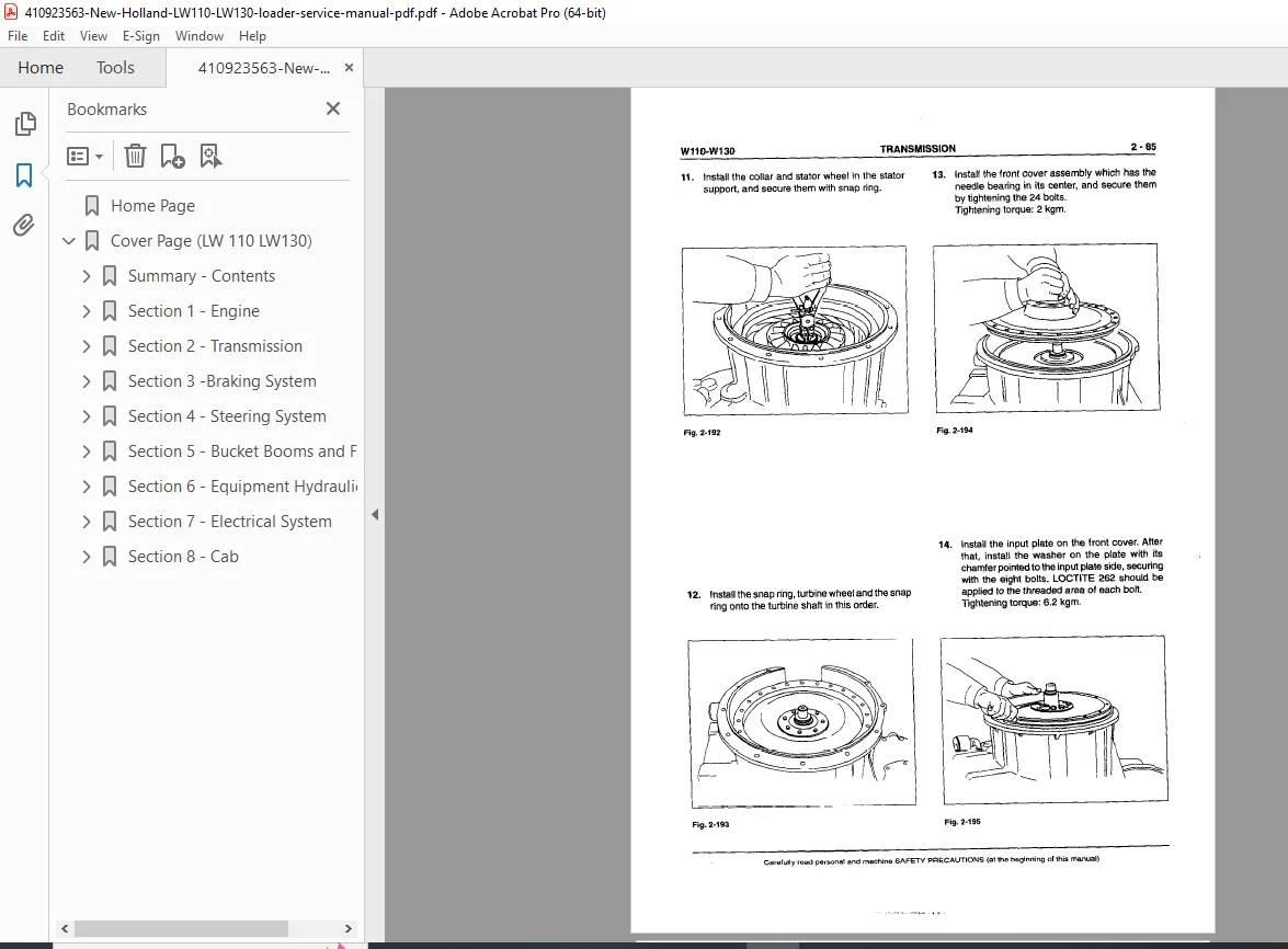
New Holland LW110 LW130 Wheel Loader Service Manual PDF
Original price was: $95.00.$28.95Current price is: $28.95.
Complete New Holland service manual for LW110 and LW130 wheel loaders. Comprehensive workshop repair guide covering engine, transmission, drive line, braking system, steering system, bucket boom and frame, hydraulic system, electrical system, and cab. Features detailed specifications, torque values, troubleshooting procedures, component removal and installation, adjustment procedures, hydraulic schematics, and electrical diagrams. Essential technical reference for construction equipment technicians servicing wheel loaders.
Description
New Holland LW110 LW130 Wheel Loader Service Manual Workshop Repair Guide PDF DOWNLOAD
DESCRIPTION
New Holland LW110 / LW130 Wheel Loader Complete Service Manual
This comprehensive factory service manual provides complete technical documentation for New Holland LW110 and LW130 wheel loaders, published in March 1999. Essential reference for heavy equipment technicians, construction equipment mechanics, and service facilities performing maintenance, repairs, and overhauls on these professional wheel loaders.
📋 FILE DETAILS
| Specification | Details |
|---|---|
| Manual Name | New Holland LW110/LW130 Service Manual |
| Document Number | 75131007 |
| Equipment Models | LW110 and LW130 Wheel Loaders |
| Publication Date | March 1999 |
| Pages | 332 pages |
| PDF Quality | Scanned factory documentation |
| File Size | 14.2 MB |
| Manufacturer | New Holland Construction |
🚜 NEW HOLLAND LW110/LW130 SPECIFICATIONS
LW110 WHEEL LOADER
Identification:
- Marking: LW110
- Model Number: 2621.iOO.OOl
Engine – Fiat 8065.25.290:
- Type: 4-stroke diesel, direct injection, turbocharged
- Net Power: 83 kW at flywheel
- Number of Cylinders: 6
- Bore x Stroke: 104 x 115 mm
- Total Displacement: 5,861 cm³
- Maximum Torque Speed: 1,500 rpm
- Maximum Power Speed: 2,300 rpm
- Firing Order: 1-5-3-6-2-4
- Injector Setting: 260 ± 12 bar
- Valve/Rocker Operation Lash:
- Intake: 0.30 mm
- Exhaust: 0.30 mm
Engine Operating Speeds:
- Minimum idle speed (no load): 790-870 rpm
- Maximum idle speed (no load): 2,430-2,530 rpm
- Converter stall speed: 2,310-2,410 rpm
- Steering stall at idle: >600 rpm
- Attachment stall: 2,300-2,400 rpm
- Full stall: 1,510-1,710 rpm
- Minimum starting temperature: -15°C
Temperature and Pressure Sensors:
- Engine coolant high temperature: 101 ± 1°C
- Engine oil low pressure switch: 0.5 ± 0.1 bar
Transmission:
- Torque converter equipped
- Multiple speed ranges
- Transmission disengagement sensor: 15 ± 1 bar
- Transmission oil high temperature sensor
- Induction sensors for gear teeth detection
Braking System:
- Disc brakes in oil bath
- Axle-mounted brake system
- Brake pump delivery at nominal speed: 26 L/min
- Brake oil low pressure sensor
- Brake lights pressure switch: 1.8 ± 0.5 bar
- Parking brake pressure switch
Hydraulic System:
- Double-acting hydraulic cylinders
- Attachment hydraulic controls
- Boom and bucket hydraulic systems
LW130 WHEEL LOADER
Similar Specifications with Enhanced Capacity:
- Larger operating weight
- Enhanced hydraulic capacity
- Similar engine platform
- Upgraded transmission components
- Higher lift capacity
- Increased bucket capacity
📖 COMPREHENSIVE SERVICE MANUAL CONTENTS
SUMMARY SECTION
Manual Organization:
- Complete table of contents
- Section index guide
- Quick reference navigation
Capacities and Fluid Types:
- Engine oil capacity and specifications
- Transmission fluid capacity and type
- Hydraulic oil capacity and grade
- Coolant capacity and specifications
- Brake fluid type
- Axle oil capacity
- Differential oil specifications
- Grease specifications
SAFETY RULES
Critical Safety Information:
Accident Prevention:
- Most accidents are preventable
- Simple safety rules compliance
- Operator responsibility
- Pre-service safety checks
Equipment Safety:
- WARNING: Hydraulic Equipment Safety
- Lower equipment to ground before servicing
- Never service with equipment raised
- Use proper support if access requires raised position
- Never rely solely on hydraulic cylinders for support
- Mechanical blocking required for safety
General Safety Rules:
- Never clean, lubricate, or adjust while machine is in motion
- Proper lockout/tagout procedures
- Personal protective equipment requirements
- Fire prevention measures
- Hydraulic system pressure hazards
- Hot fluid warnings
- Electrical system precautions
UNITS OF MEASURE
Measurement Standards:
- Metric units (SI)
- Conversion charts
- Torque specifications
- Pressure measurements
- Temperature scales
- Fluid capacities
TIGHTENING TORQUES
Torque Specification Tables:
- Bolt size and torque values
- Thread pitch specifications
- Material grade considerations
- Special torque requirements
- Thread locking compound applications
- Assembly sequences
- Critical fastener identification
SECTION 1: ENGINE
Fiat 8065.25.290 Engine Service:
Engine Systems:
- Fuel System:
- Fuel injection system
- Injection pump service
- Injector removal and installation
- Injector testing and adjustment
- Fuel filters
- Fuel lines and connections
- Fuel tank service
- Cooling System:
- Radiator service
- Water pump removal and installation
- Thermostat testing and replacement
- Coolant hoses
- Fan and fan belt
- Temperature sensors
- Coolant circulation
- Lubrication System:
- Oil pump service
- Oil filter replacement
- Oil pan removal
- Oil pressure testing
- Lubrication passages
- Air Intake System:
- Air filter service
- Turbocharger maintenance
- Intake manifold
- Air cleaner housing
- Turbocharged system diagnosis
- Exhaust System:
- Exhaust manifold
- Muffler and piping
- Turbocharger exhaust
- System leaks and repairs
Engine Mechanical:
- Cylinder head removal and installation
- Valve train service
- Valve adjustment procedures
- Camshaft removal
- Piston and connecting rod service
- Crankshaft service
- Engine block inspection
- Bearing replacement
- Timing gear service
- Engine assembly procedures
Engine Electrical:
- Starting system
- Alternator service
- Engine sensors
- Wiring harness
- Ground connections
SECTION 2: DRIVE LINE/TRANSMISSION
Transmission System:
Torque Converter:
- Operation principles
- Testing procedures
- Removal and installation
- Inspection criteria
- Overhaul procedures
Transmission Assembly:
- Disassembly procedures
- Component inspection
- Bearing and seal replacement
- Clutch pack service
- Planetary gear sets
- Valve body service
- Pump assembly
- Assembly procedures
- Adjustment specifications
Drive Shaft:
- Universal joint service
- Drive shaft removal
- Balance verification
- Replacement procedures
Axles:
- Front axle service
- Rear axle service
- Differential service
- Disc brake system
- Axle shaft replacement
- Bearing adjustment
- Oil seal replacement
Brakes in Oil Bath:
- Disc brake service
- Caliper overhaul
- Brake adjustment
- Hydraulic system service
- Performance testing
SECTION 3: BRAKING SYSTEM
Service Brake System:
Hydraulic Brake Components:
- Master cylinder service
- Brake pump operation
- Accumulator testing
- Brake control valve
- Pressure sensors
- Hydraulic lines and fittings
Brake System Service:
- Bleeding procedures
- Pressure testing
- Component replacement
- Adjustment procedures
- Performance verification
Parking Brake:
- Mechanical parking brake
- Adjustment procedures
- Cable replacement
- Pressure switch testing
Safety Features:
- Brake pressure warning system
- Brake light activation
- Emergency brake procedures
SECTION 4: STEERING SYSTEM
Hydrostatic Steering:
Steering Components:
- Steering pump service
- Orbital steering unit
- Hydraulic cylinders
- Priority valve
- Flow divider
- Accumulator
Steering System Service:
- Pump removal and installation
- Cylinder replacement
- System bleeding
- Pressure testing
- Steering linkage
- Articulation joint service
- Pin and bushing replacement
Steering Adjustments:
- Steering wheel position
- Cylinder stroke adjustment
- Pressure relief settings
- Flow control adjustment
SECTION 5: BUCKET BOOM AND FRAME
Loader Linkage:
Boom Assembly:
- Boom structure
- Lift arm service
- Pivot points
- Pin replacement
- Bushing service
- Lubrication points
Bucket Linkage:
- Bucket attachment
- Quick coupler (if equipped)
- Linkage geometry
- Pin and bushing service
- Dump angle adjustment
Frame Structure:
- Main frame inspection
- Weld crack detection
- Structural repair procedures
- Articulation frame service
- Center pin service
Hydraulic Cylinders:
- Lift cylinders
- Tilt cylinders
- Cylinder removal
- Seal replacement
- Rod inspection
- Cylinder repair
SECTION 6: HYDRAULIC SYSTEM
Complete Hydraulic System:
Hydraulic Pump:
- Pump types and operation
- Pump removal and installation
- Flow testing
- Pressure testing
- Pump overhaul
- Drive coupling service
Control Valves:
- Main control valve assembly
- Spool valve service
- Detent adjustment
- Pilot controls
- Valve disassembly
- Inspection procedures
- Seal replacement
Hydraulic Cylinders:
- Cylinder types
- Disassembly procedures
- Seal kit installation
- Rod reconditioning
- Tube inspection
- Assembly procedures
- Testing and adjustment
Hydraulic Lines and Fittings:
- Hose replacement
- Fitting types
- Pressure ratings
- Routing guidelines
- Clamp locations
Hydraulic Filters:
- Filter locations
- Replacement intervals
- Filter specifications
- Bypass valve testing
Hydraulic Reservoir:
- Tank capacity
- Breather service
- Drain and refill
- Internal baffles
- Suction strainer
Hydraulic Schematics:
- Complete hydraulic diagrams
- Circuit identification
- Component location
- Pressure specifications
- Flow rates
SECTION 7: ELECTRICAL SYSTEM
Electrical Components:
Battery and Charging:
- Battery specifications
- Charging system
- Alternator testing
- Voltage regulator
- Wiring connections
Starting System:
- Starter motor service
- Solenoid testing
- Starting circuit
- Safety interlocks
Lighting System:
- Headlights
- Work lights
- Tail lights
- Turn signals
- Hazard lights
- Instrument lighting
Instruments and Gauges:
- Instrument cluster
- Gauge calibration
- Sender unit testing
- Warning lights
- Hour meter
Electrical Schematics:
- Complete wiring diagrams
- Circuit identification
- Connector pinouts
- Wire color codes
- Fuse locations and ratings
- Relay identification
Sensors and Switches:
- Temperature sensors
- Pressure switches
- Seat switch
- Neutral safety switch
- Brake light switch
- Reverse alarm
SECTION 8: CAB
Operator Cab:
Cab Structure:
- ROPS (Roll-Over Protective Structure)
- FOPS (Falling Object Protective Structure)
- Cab mounting system
- Isolation mounts
- Structural integrity
Cab Components:
- Seat and seatbelt
- Steering wheel and column
- Control levers
- Pedal assembly
- Door and windows
- Mirrors
HVAC System:
- Heater operation
- Air conditioning (if equipped)
- Ventilation system
- Filter replacement
- Control panel
Cab Removal:
- Preparation procedures
- Disconnect procedures
- Lifting points
- Installation procedures
🔧 MAINTENANCE PROCEDURES
Scheduled Maintenance:
- Daily checks
- 10-hour service
- 50-hour service
- 250-hour service
- 500-hour service
- 1,000-hour service
- Annual service
- Component life limits
Lubrication:
- Grease point locations
- Lubrication chart
- Grease specifications
- Lubrication intervals
- Special lubrication requirements
🛠️ TROUBLESHOOTING GUIDES
Systematic Diagnostics:
- Engine problems
- Transmission issues
- Hydraulic system faults
- Brake system problems
- Steering difficulties
- Electrical failures
- Performance issues
Diagnostic Procedures:
- Symptom analysis
- Testing procedures
- Component isolation
- Pressure and flow testing
- Electrical testing
💡 TECHNICAL HIGHLIGHTS
Wheel Loader Features:
- Articulated steering
- Hydrostatic power steering
- Torque converter transmission
- Load-sensing hydraulics
- ROPS/FOPS certified cab
- Multiple attachment capability
👥 ESSENTIAL FOR TECHNICIANS
This manual is critical for:
- Heavy Equipment Mechanics servicing wheel loaders
- Construction Equipment Technicians performing repairs
- Fleet Maintenance Personnel managing loader fleets
- Rental Equipment Service Centers maintaining inventory
- Mining and Quarry Mechanics supporting operations
- Agricultural Equipment Technicians servicing farm loaders
- Technical Training Programs teaching heavy equipment repair
🏗️ APPLICATIONS
Industry Usage:
- Construction sites
- Quarries and mines
- Material handling
- Agriculture
- Landscaping
- Snow removal
- Waste management
- Forestry operations
⚙️ SERVICE CAPABILITIES
Complete Coverage:
- Component-level repair
- System overhauls
- Hydraulic service
- Engine rebuilding
- Transmission overhaul
- Electrical diagnostics
- Frame and structure repair
📐 TECHNICAL SPECIFICATIONS
Operating Specifications:
- Bucket capacity ranges
- Lift height
- Dump clearance
- Operating weight
- Wheelbase
- Turning radius
- Travel speeds
- Gradeability
🔍 DIAGNOSTIC TOOLS
Required Equipment:
- Pressure gauges
- Flow meters
- Multimeter
- Scan tools (if equipped)
- Torque wrenches
- Specialty tools for specific components
⚠️ IMPORTANT SAFETY
Service Precautions:
- High-pressure hydraulics
- Heavy component handling
- Pinch points
- Hot surfaces
- Electrical hazards
- Rotating components
- Stored energy (springs, accumulators)
⚡ INSTANT DOWNLOAD – SERVICE NEW HOLLAND LOADERS PROFESSIONALLY! This comprehensive 334-page New Holland factory service manual provides complete maintenance and repair procedures for LW110 and LW130 wheel loaders. From routine service to major overhauls, every system is documented with detailed procedures, torque specifications, and hydraulic schematics. Download immediately and gain expert-level knowledge for New Holland wheel loader service and repair!
Pricing Rationale:
- 334 pages of comprehensive technical content
- Covers 2 loader models (LW110/LW130)
- Factory official service manual
- Complete engine, transmission, hydraulic coverage
- Heavy equipment documentation
- Professional construction equipment
- Detailed troubleshooting procedures
- Hydraulic schematics included
- Essential for heavy equipment technicians
- Specialized construction machinery
- Complete system overhaul procedures
- Professional workshop resource