New Holland MH City to MH 8.6 Tier3 Hydraulic Manual – PDF DOWNLOAD
Original price was: $65.95.$23.95Current price is: $23.95.
New Holland MH City to MH 8.6 Tier3 Hydraulic Manual
Description
New Holland MH City to MH 8.6 Tier3 Hydraulic Manual
FILE DETAILS:
New Holland MH City to MH 8.6 Tier3 Hydraulic Manual
Language : English
Pages : 112
Downloadable : YES
Format : PDF
Size : 9.73 MB
DESCRIPTION:
New Holland MH City to MH 8.6 Tier3 Hydraulic Manual
SAMPLE PAGES FROM THE MANUAL:
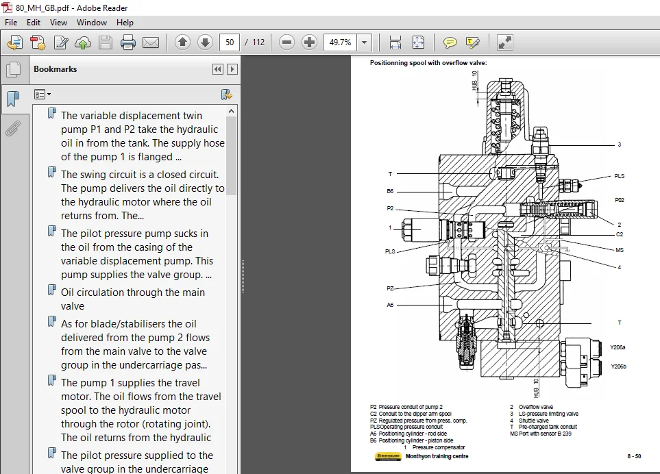
The variable displacement twin pump P1 and P2 take the hydraulic oil in from the tank. The supply hose of the pump 1 is flanged on the main valve on the right-hand side, seen in travel direction. The oil of the pump 1 flows to the main valve to pass, one after the other, the travel spool, boom spool, bucket spool, dipper arm spool and returns to the tank passing through the tank channel, radiator and return filter. The supply hose of the pump 2 is flanged on the main valve on the left-hand side, seen in travel direction.
- The oil of the pump 1 flows to the main valve to pass, one after the other, the additional spool for hammer/shears, positioning cylinder spool, bucket spool, boom spool, stabiliser/blade spool and returns to the tank passing through the tank channel, radiator and return filter.
- The pumps P1 and P2 supply the oil to the travel motor and cylinders according to the stroking of the respective spools. The oil returns, depending on its viscosity, through differential pressure valves, oil cooler or directly to the tank through the return filter.
- The swing circuit is a closed circuit. The pump delivers the oil directly to the hydraulic motor where the oil returns from. The leakage oil is compensated for by the incorporated charging pump. This pump takes in the oil from the hydraulic tank and keeps the closed circuit under pressure. The swing directions are changed by inverting the oil flow leaving the pump.
TABLE OF CONTENTS:
New Holland MH City to MH 8.6 Tier3 Hydraulic Manual
The variable displacement twin pump P1 and P2 take the hydraulic oil in from the tank. The supply hose of the pump 1 is flanged .............................................................................................................................  3
The swing circuit is a closed circuit. The pump delivers the oil directly to the hydraulic motor where the oil returns from. The.............................................................................................................................  3
The pilot pressure pump sucks in the oil from the casing of the variable displacement pump. This pump supplies the valve group. .............................................................................................................................  3
Oil circulation through the main valve.......................................................................................................................................................................................................................  3
As for blade/stabilisers the oil delivered from the pump 2 flows from the main valve to the valve group in the undercarriage pas.............................................................................................................................  5
The pump 1 supplies the travel motor. The oil flows from the travel spool to the hydraulic motor through the rotor (rotating joint). The oil returns from the hydraulic motor through the retarder valve, rotor and main valve to the tank...................  5
The pilot pressure supplied to the valve group in the undercarriage operates the parking brake, gearshift, oscillating axle blocking as well as creep speed of the travel motor..............................................................................  5
Description:.................................................................................................................................................................................................................................................  6
The drive assembly consists mainly of the Diesel engine, multi-circuit pump, gear pumps and hydraulic oil tank...............................................................................................................................................  6
The CNH Diesel engine (1) belongs to the New Engine Family (NEF). This engine is a 4 or 6 in-line cylinders unit completed with turbocharger and downstream intake air radiator..............................................................................  6
The multi-circuit pump component (2) is driven by the engine through an elastic coupling. The component comprises the variable displacement twin pump (3) with integrated pilot pressure pump and swing pump (4).............................................  6
The double gear pump (5+6) is flanged to the power take-off of the Diesel engine to be driven................................................................................................................................................................  6
The pump (5) supplies the steering, circuits and force feed travel circuit (25 a,d 30 km/h machines).........................................................................................................................................................  6
The pump (6) supplies the service brake, the work brake and grab rotation unit...............................................................................................................................................................................  6
The hydraulic oil tank stores clean and cooled oil for the pumps.............................................................................................................................................................................................  6
The variable displacement twin pump (3) takes in the oil through the port S. The built-in pilot pressure pump takes the oil from the casing of the variable displacement twin pump...........................................................................  6
The charging pump incorporated in the swing pump (4) takes the oil from a separate line, whilst the double gear pump is directly supplied from the hydraulic oil tank........................................................................................  6
Description:.................................................................................................................................................................................................................................................  7
The pump unit consists of the gear transmission, variable displacement twin pump, swing pump and pilot pressure gear pump....................................................................................................................................  7
The engine drives the gear transmission through an elastic coupling..........................................................................................................................................................................................  7
Two of the four gearwheels of the trans unit drive the variable displacement pump (2). An intermediate gearwheel moves the pilot pressure pump (3) and power take-off for the swing pump (4).................................................................  7
The transmission ratio from the drive train to the variable displacement pump and swing pump is 1............................................................................................................................................................  7
The variable displacement pump (2) has been made up from 2 axial-piston bent-axis pumps accommodated in a single casing. Each pump is equipped with its separate regulator stroking the pump to regulate the flow rate independently from the other pump.....  7
The pilot pressure is delivered by a gear pump through the port (3)..........................................................................................................................................................................................  7
The swing pump is of swashplate design. The angle of inclination determines the speed of the uppercarriage, whilst the direction of inclination defines the sense of rotation of the uppercarriage...........................................................  7
Hydraulic tank...............................................................................................................................................................................................................................................  8
	Description:.............................................................................................................................................................................................................................................  8
	The tank incorporating the filter chamber and return oil filter stores the hydraulic oil. The centrally arranged cover including.........................................................................................................................  8
	The oil pressure switch S15 on the filter chamber monitors the filter. With contaminated filter element and indamissibly high co.........................................................................................................................  8
	The aeration filter keeps the oil clean from environmental impacts. An integrated two-way valve provides, on one side, for atmos.........................................................................................................................  8
	The temperature sensor R14, a NTC-transducer (negative temperature coefficient) detects the hydraulic oil temperature. The temperature signal in form of an electric resistance is fed to the PCS-box for temperature control............................  8
Pumps........................................................................................................................................................................................................................................................  9
	1. Pilot pressure pump...................................................................................................................................................................................................................................  9
	2. Seal..................................................................................................................................................................................................................................................  9
	3. Double pump...........................................................................................................................................................................................................................................  9
	A3 Pilot pressure outlet.................................................................................................................................................................................................................................  9
	Pumps MH6.6 - MH8.6......................................................................................................................................................................................................................................  9
	A4VG swing pump..........................................................................................................................................................................................................................................  9
	A8V0 main double pump....................................................................................................................................................................................................................................  9
	1 suctionport............................................................................................................................................................................................................................................ 10
	2 barrel................................................................................................................................................................................................................................................. 10
	3 center tappet.......................................................................................................................................................................................................................................... 10
	4 springs................................................................................................................................................................................................................................................ 10
	5 distribution plate..................................................................................................................................................................................................................................... 10
	6 shape in the regulation bloc........................................................................................................................................................................................................................... 10
	8 servo-piston........................................................................................................................................................................................................................................... 10
	A1, A2 pumps outlets..................................................................................................................................................................................................................................... 10
Main pumps regulation........................................................................................................................................................................................................................................ 11
	A : Regulated pressure to the servo-piston............................................................................................................................................................................................................... 16
	HD : Pump pressure (about 8 bar in neutral).............................................................................................................................................................................................................. 16
	X3 : Torque regulated pressure from Y10.................................................................................................................................................................................................................. 16
	Y3 : Pilot pressure 45 bar............................................................................................................................................................................................................................... 16
	X1 : Flow demand regulated pressure...................................................................................................................................................................................................................... 16
	Values with the engine at 2000 rpm....................................................................................................................................................................................................................... 17
	Values with the engine at 1850 rpm....................................................................................................................................................................................................................... 18
	Values with the engine at 2150 rpm....................................................................................................................................................................................................................... 19
	Values with the engine at 2000 rpm....................................................................................................................................................................................................................... 20
	Values with the engine at 2000 rpm....................................................................................................................................................................................................................... 21
8a_MH_section_GB.pdf.........................................................................................................................................................................................................................................  0
	Travel................................................................................................................................................................................................................................................... 72
	Boom..................................................................................................................................................................................................................................................... 31
	Dipper arm............................................................................................................................................................................................................................................... 38
	Positionning............................................................................................................................................................................................................................................. 47
	Bucket................................................................................................................................................................................................................................................... 42
	Hammer................................................................................................................................................................................................................................................... 53
	Hammer/crusher........................................................................................................................................................................................................................................... 57
	Scissors................................................................................................................................................................................................................................................. 63
	Configuration of undercarriage........................................................................................................................................................................................................................... 78
	Cylinders................................................................................................................................................................................................................................................ 86
	Boom + Bucket + Dipper arm............................................................................................................................................................................................................................... 77
	SETTINGS VALUES.......................................................................................................................................................................................................................................... 95
	Hydraulic shematics...................................................................................................................................................................................................................................... 97
	Magnet................................................................................................................................................................................................................................................... 70
	Control valve............................................................................................................................................................................................................................................ 22
8c_MH_section_GB.pdf.........................................................................................................................................................................................................................................  0
	Hydraulic Checks mobile excavator (MH-units):............................................................................................................................................................................................................109
NEW HOLLAND MH CITY TO MH 8.6 TIER3 HYDRAULIC MANUAL – PDF DOWNLOAD:
IMAGES PREVIEW OF THE MANUAL:
PLEASE NOTE:
- This is the SAME exact manual used by your dealers to fix your vehicle.
- The same can be yours in the next 2-3 mins as you will be directed to the download page immediately after paying for the manual.
- Any queries / doubts regarding your purchase, please feel free to contact [email protected]