New Holland MH4.6 MHPlus C Operation and Maintenance Instruction Manual 604.21.812.00 – PDF DOWNLOAD
Original price was: $78.00.$26.95Current price is: $26.95.
New Holland MH4.6 MHPlus C Operation and Maintenance Instruction Manual 604.21.812.00 – PDF DOWNLOAD
Description
New Holland MH4.6 MHPlus C Operation and Maintenance Instruction Manual 604.21.812.00 – PDF DOWNLOAD
IMAGES PREVIEW OF THE MANUAL:
DESCRIPTION:
New Holland MH4.6 MHPlus C Operation and Maintenance Instruction Manual 604.21.812.00 – PDF DOWNLOAD
- SAFETY PRECAUTIONS
GENERALITIES - Read the Operation and Maintenance Instruction Manual carefully before starting, operating, maintaining, fuelling or servicing the machine. Carefully read the explanation to each and all safety signs in the special section of this Manual before starting, operating, maintaining, fuelling or servicing the machine. Machine-mounted safety plates are colour coded
- yellow with black borders when they refer to points where special ATTENTION must be paid and failure to observe them may cause a serious DANGER to the integrity of machine operators. They are white with red borders and black lettering when they refer to a FORBIDDEN practice. It is fundamental that all machine operators know very well the meaning of each safety plate as this considerably decreases operating hazards and accidents. Do not allow unauthorised personnel to operate
- or service this machine. Do not wear rings, wrist watches, jewellery, loose or hanging garments, such as ties, torn clothing, scarves, unbuttoned or unzipped jackets that can get caught in moving parts. Wear certified safety clothes such as: hard hat, no-slip footwear, heavy gloves, ear protection, safety glasses , reflector vests, respirators every time the job requires it. Ask
- your employer about safety regulations in force and protective equipment. Always keep the operator’s compartment, step plates, grab-rails and handles clean and clear of foreign objects, oil, grease, mud or snow to minimise the danger of slipping or stumbling. Remove mud or grease from your shoes before operating the machine. Do not jump on or off the machine. Always keep both hands and one foot, or both feet and one hand in contact with steps and/or grab rails. Do not use controls or hoses as hand holds. Hoses and controls are movable parts and do not provide solid support. Besides, controls may be
- inadvertently moved and cause unexpected movement of the machine or its attachments. Never operate the machine or its attachments from any position other than sitting in the driver’s seat. Keep head, body, limbs, hands and feet inside the operator’s compartment at all times to reduce exposure to external hazards. Be careful of possible slippery conditions of the steps and hand rails as well as of the ground around the machine. Wear protective boots or shoes with the soles made of
- highly no-slip rubber. Do not leave the machine until it has come to a complete stop. Always check height, width and weight limitations which may be encountered in the working site and ensure the machine does not exceed them. Assess exact paths of gas ducts, water mains, telephone lines, sewers, overhead and underground electric lines and all other possible obstacles.
- Such paths should be opportunely defined by competent Authorities. If necessary, require that the service is interrupted or said installations are moved prior to starting the work. You must know the working capacity of the machine. Define the rear upperstructure swing area and provide for opportune barriers to prevent access into it. Never exceed machine lifting capacity. Remain within the limits shown in the loading capacity chart located on the machine
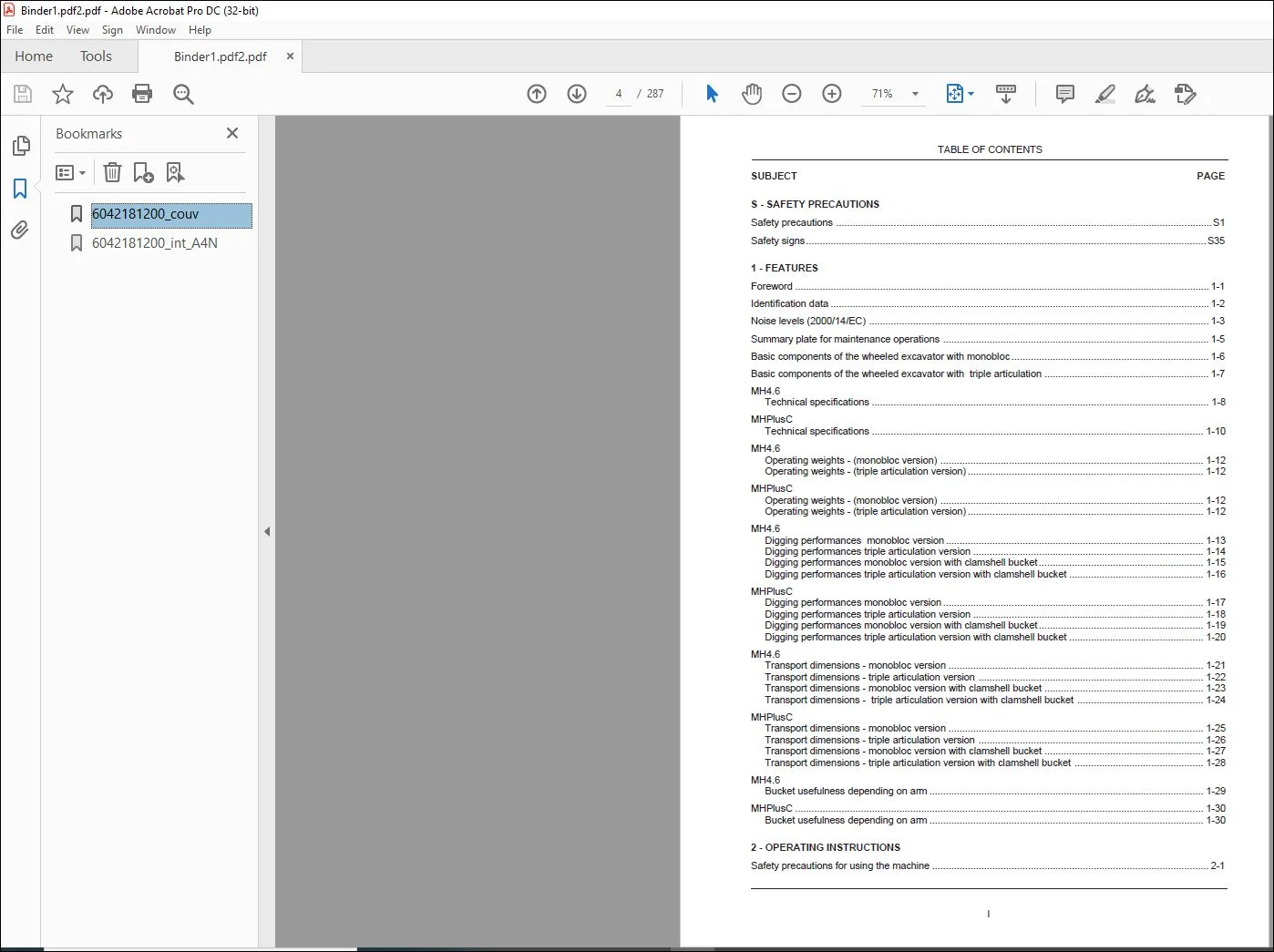
TABLE OF CONTENTS:
New Holland MH4.6 MHPlus C Operation and Maintenance Instruction Manual 604.21.812.00 – PDF DOWNLOAD
SUBJECT PAGE
S – SAFETY PRECAUTIONS
Safety precautions S1
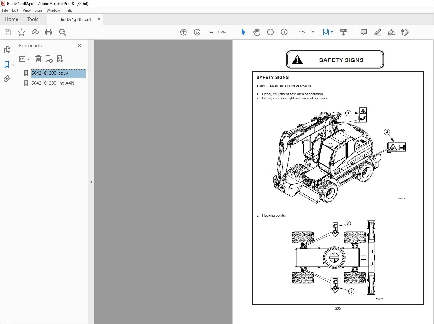
Safety signsS35
1 – FEATURES
Foreword 1-1
Identification data 1-2
Noise levels (2000/14/EC) 1-3
Summary plate for maintenance operations 1-5
Basic components of the wheeled excavator with monobloc 1-6
Basic components of the wheeled excavator with triple articulation 1-7
MH46
Technical specifications 1-8
MHPlusC
Technical specifications 1-10
MH46
Operating weights – (monobloc version) 1-12
Operating weights – (triple articulation version) 1-12
MHPlusC
Operating weights – (monobloc version) 1-12
Operating weights – (triple articulation version) 1-12
MH46
Digging performances monobloc version 1-13
Digging performances triple articulation version 1-14
Digging performances monobloc version with clamshell bucket 1-15
Digging performances triple articulation version with clamshell bucket 1-16
MHPlusC
Digging performances monobloc version 1-17
Digging performances triple articulation version 1-18
Digging performances monobloc version with clamshell bucket 1-19
Digging performances triple articulation version with clamshell bucket 1-20
MH46
Transport dimensions – monobloc version 1-21
Transport dimensions – triple articulation version 1-22
Transport dimensions – monobloc version with clamshell bucket 1-23
Transport dimensions – triple articulation version with clamshell bucket 1-24
MHPlusC
Transport dimensions – monobloc version 1-25
Transport dimensions – triple articulation version 1-26
Transport dimensions – monobloc version with clamshell bucket 1-27
Transport dimensions – triple articulation version with clamshell bucket 1-28
MH46
Bucket usefulness depending on arm 1-29
MHPlusC 1-30
Bucket usefulness depending on arm 1-30
2 – OPERATING INSTRUCTIONS
Safety precautions for using the machine
Controls and instruments 2-2
Anti-start device (anti-theft device) 2-3
Safety lever 2-4
Key-start switch 2-5
Upperstructure swing locking control 2-5
Travel control pedal 2-6
Left-hand control lever 2-7
Right-hand control lever 2-8
Brake control pedal 2-10
Pedal for hydraulic breaker control 2-10
Pedal for articulated arm positioner control 2-11
Steering wheel 2-11
Steering column panel 2-12
Monitor panel 2-17
Right hand instrument panel 2-25
Rh Knob console 2-30
Air conditioning 2-30
Lh Knob console 2-33
Radio (optional) 2-34
Hour-counter 2-38
Operator’s compartment 2-39
Adjusting the seat 2-39
Seat belt 2-41
Cab 2-42
Door 2-42
Front windscreens and windows 2-43
Cab accessories 2-44
Emergency exit 2-45
Mirrors 2-45
Grab rails and steps 2-46
Using the machine 2-47
Refuelling 2-48
Checks before engine start-up 2-49
Key-start switch 2-49
Checks after engine start-up 2-50
Starting the engine 2-50
Starting the engine after prolonged storage 2-51
Cold weather warm-up 2-51
Starting the engine using booster batteries 2-52
Stopping the engine 2-53
Travel control pedal 2-54
Road travelling procedures 2-55
Road travelling 2-55
Homologation for road 2-55
Traffic (italy) 2-55
Emergency boom lowering procedure 2-61
Excavator removal 2-62
Safety lever 2-64
Control levers 2-65
Machine warm-up 2-66
Engine speed hand control 2-67
A/I control button 2-67
Memory button 2-67
Operating the machine 2-68
Major operating norms 2-69
Precautions during operation 2-73
Parking the machine 2-74
Precautions for traveling on slopes 2-75
Handling of overhead loads 2-77
Reading key for the liftable load chart located in the cab 2-79
Bucket installation 2-80
Bucket teeth 2-81
Road transport 2-82
Norms for transport 2-82
Norms for loading/unloading the machine on a trailer 2-82
Loading the machine on a trailer 2-83
Unloading the machine from a trailer 2-84
Sea transport 2-85
Craning the machine for sea transport 2-85
Precautions in cold weather 2-86
Prolonged machine inactivity 2-87
Using the machine after prolonged storage 2-88
Decommissioning of the machine 2-88
3 – OPTIONS AND VARIANTS
Hydraulic breaker 3-1
Hydraulic breaker selection and installation 3-1
Precautions when using the hydraulic breaker 3-1
Hydraulic breaker control 3-4
Crusher 3-6
Crusher selection and installation 3-6
Precautions to be observed when 3-6
Using the crusher 3-6
Nibbler control 3-8
Hydraulic oil and filter element service interval 3-9
Equipment rotation system 3-10
Equipment swing control 3-10
Clamshell bucket system 3-11
Clamshell bucket control 3-11
Cab protection (FOPS) 3-12
Fuel transfer pump 3-13
4 – MAINTENANCE
Maintenance safety precautions 4-1
Generalities 4-2
Checking the hour-counter regularly 4-3
Service reminder plate 4-3
Preparing the machine for maintenance 4-4
Hood and access covers 4-5
External visual inspection 4-6
Engine oil 4-7
Checks before starting daily work 4-7
Hydraulic system oil 4-8
Engine cooling system 4-9
Fuel tank 4-10
Windscreen washer tank 4-11
Cyclonic pre-filter 4-11
Fuel pre-filter 4-11
Machine lubrication and maintenance general chart 4-12
After 100 hours of operation 4-13
Bucket links 4-13
Boom and arms 4-14
Stabilizers or blade 4-15
Front axle swing bushing 4-15
After 250 hours of operation 4-16
Outer and inner circulation air filters 4-16
Air filter: Outer element 4-18
Swing reduction gear oil 4-19
Oil for reduction gears front axle 4-20
Front and rear axle oil 4-21
Transmission oil 4-21
Hardware tightening torques 4-22
Tyres 4-30
Fuel tank 4-31
Hoses, lines and connections 4-32
Fuel hoses 4-40
Hydraulic oil reservoir 4-41
After 500 hours of operation 4-42
Engine oil and filter 4-42
Fuel filter 4-44
Hydraulic system oil filter 4-46
Slewing ring bearing 4-48
Slewing ring teeth 4-49
Front axle 4-50
Engine cooling system 4-51
Accumulator charge 4-52
Brake and pilot system oil filter 4-52
Air conditioner – optional 4-54
After 1000 hours of operation 4-55
Air filter: Outer element 4-55
After 1500 hours of operation 4-56
Fuel pre-filter 4-56
Alternator – fan belt 4-58
After 2000 hours of operation 4-59
Swing reduction gear oil 4-59
Transmission oil, axles oil 4-61
Engine cooling system 4-63
Air filter: Inner element 4-66
After 2500 hours of operation 4-67
Hydraulic system oil 4-67
After 3000 hours of operation 4-73
Engine valves 4-73
Filling chart model MH46 4-74
Filling chart model MHPlusC 4-75
5 – TROUBLESHOOTING
Engine 5-1
Electrical system 5-6
Controls 5-8
6 – ELECTRICAL SYSTEM
Generalities 6-1
Batteries 6-2
Fuses 6-4
Electrical system reading key 6-6
Customer Support: [email protected]
https://vimeo.com/730971954
PLEASE NOTE:
- This is the SAME exact manual used by your dealers to fix your vehicle.
- The same can be yours in the next 2-3 mins as you will be directed to the download page immediately after paying for the manual.
- Any queries / doubts regarding your purchase, please feel free to contact [email protected]
S.m