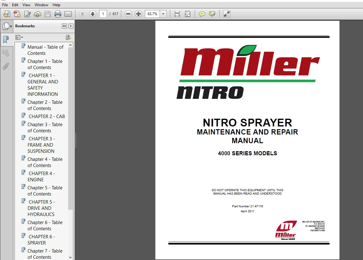
New Holland Miller Nitro Sprayer 4000 Series Models Repair Manual (21-47116) New Holland Miller – PDF Download
Original price was: $95.95.$39.95Current price is: $39.95.
- New Holland Miller Nitro Sprayer 4000 Series Models Service Repair Manual
- Publication Number:21-47116
Description
New Holland Miller Nitro Sprayer 4000 Series Models Repair Manual (21-47116) New Holland Miller
File Details:
New Holland Miller Nitro Sprayer 4000 Series Models Repair Manual_21-47116
Size: 105 MB
Format: PDF
Language: English
Number of Pages: 617 pages
Brand: New Holland
Type of document: Service Manual
Model: 4000 Series Models
Part No: 21-47116
NEW HOLLAND MILLER NITRO SPRAYER 4000 SERIES MODELS REPAIR MANUAL (21-47116) NEW HOLLAND MILLER – PDF DOWNLOAD:
Image Preview:
Description:
New Holland Miller Nitro Sprayer 4000 Series Models Repair Manual (21-47116) New Holland Miller
- This Maintenance and Repair Manual is provided to instruct the maintenance technician on repair procedures of the Miller Nitro Sprayer. Complete Remove and Install procedures are provided. When needed, additional procedures for Disassembly, Inspect, Clean, Measure, and Assembly are provided.
- Make sure the maintenance technician reads and understands this manual before working on the Miller Nitro Sprayer. Failure to follow the recommended procedures may result in injury and equipment damage, and could void the warranty.
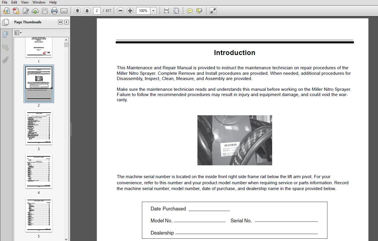
- The machine serial number is located on the inside front right side frame rail below the lift arm pivot. For your convenience, refer to this number and your product model number when requiring service or parts information. Record the machine serial number, model number, date of purchase, and dealership name in the space provided below.
Table of Contents:
New Holland Miller Nitro Sprayer 4000 Series Models Repair Manual (21-47116) New Holland Miller
Safety Precautions 1-3
Notes, Notices, Cautions, Warnings, and Dangers Definitions 1-3
General Safety Precautions 1-4
Sprayer Safety Precautions 1-5
SPRAYER OPERATIONS 1-5
SPRAYER SERVICE AND MAINTENANCE 1-5
Chemicals and Hazardous Substances Safety Precautions 1-5
HAZARDOUS SUBSTANCE ALERT 1-5
Engine Safety Precautions 1-6
ENGINE OPERATION 1-6
Wheels and Tires Safety Precautions 1-7
Electrical Safety Precautions 1-7
OPERATION OF ELECTRICAL COMPONENTS 1-7
Towing Safety Precautions 1-8
Moving a Downed Vehicle 1-8
Safety Sign and Decal Locations 1-11
SAFETY SIGNS 1-11
Major Components Locations 1-15
Hoses/Fittings – General 1-16
Application Basics 1-16
Bending, Motion, Routing 1-16
Hose and Fitting Care 1-16
Fittings Specifications 1-18
TIGHTENING HYDRAULIC FITTINGS 1-18
TIGHTENING FLARE TYPE FITTINGS 1-19
Hardware Torque Specifications 1-20
4000 Series Nitro Sprayer Models Pressure Settings 1-27
Location of Electrical Relays, Breakers, and Fuses 1-32
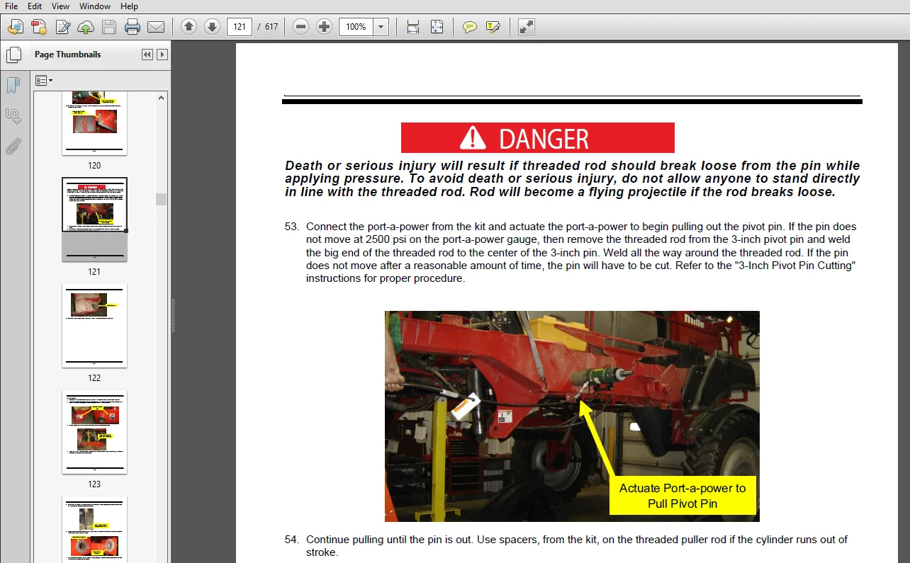
Miller Nitro Sprayer Hydraulic Oil Recommendation 1-34
Blaster Extended Antifreeze/Coolant 1-37
Nitro Sprayer Model Specifications 1-38
Model 4215 / 4215HT 1-38
Model 4240HT 1-39
Model 4275 1-40
Model 4315 1-41
Model 4365 1-42
CHAPTER 2 – CAB
General Notices, Cautions, Warnings, and Dangers For Cab Procedures 2-3
Cab Air Bags 2-4
REMOVAL 2-4
INSTALLATION 2-4
Cab Filters 2-4
CLEAN/CHANGE 2-4
Recirculation Air Filter 2-4
Cab Air (Charcoal) Filter 2-5
AC Recirculation Blower Motor 2-5
REMOVAL 2-5
INSTALLATION 2-6
AC Blower Motor 2-6
REMOVAL 2-6
INSTALLATION 2-6
AC Evaporator Heater 2-7
REMOVAL 2-7
INSTALLATION 2-8
AC Actuator Water Valve 2-9
REMOVAL 2-9
INSTALLATION 2-10
AC Duct Work 2-11
REMOVAL 2-11
RH AC Vent 2-11
LH AC Vent 2-11
INSTALLATION 2-12
LH AC Vent 2-12
RH AC Vent 2-12
Cab Interior Convenience Electrical Outlets Power Strip 2-13
GENERAL INFORMATION 2-13
Cab Interior Panels and Floor Mat 2-14
REMOVAL 2-14
Floor Mat 2-14
Front Interior Panel 2-14
Overhead Console Panel 2-14
Overhead Interior Light 2-16
Headliner 2-17
INSTALLATION 2-18
Headliner 2-18
Overhead Interior Light 2-20
Overhead Console Panel 2-21
Front Interior Panel 2-22
Floor Mat 2-22
Cab Roof 2-23
REMOVAL 2-23
INSTALLATION 2-23
Cab Steering Column Covers 2-24
REMOVAL 2-24
INSTALLATION 2-24
Cab Windshield 2-25
REPLACEMENT 2-25
Cab Windshield Wiper Motor 2-25
REMOVAL 2-25
INSTALLATION 2-25
Operator Control Console 2-25
REMOVAL 2-25
INSTALLATION 2-26
Operator Seat 2-27
REMOVAL 2-27
INSTALLATION 2-27
Operator Seat Suspension 2-27
REMOVAL 2-27
INSTALLATION 2-27
Training Seat 2-28
REMOVAL 2-28
INSTALLATION 2-28
AC/Heater Housing Cover 2-29
REMOVAL 2-29
INSTALLATION 2-30
AC Hoses 2-31
REMOVAL 2-31
INSTALLATION 2-31
CHAPTER 3 – FRAME AND SUSPENSION
General Notices, Cautions, Warnings, and Dangers For Frame and Suspension Procedures 3-3
Rear Deck and Platforms 3-4
REAR DECK 3-4
Removal 3-4
Installation 3-4
MID-PLATFORM 3-5
Removal 3-5
Installation 3-5
FRONT PLATFORM 3-6
Removal 3-6
Installation 3-6
Suspension Cylinders 3-7
SUSPENSION SYSTEM – GENERAL 3-7
SUSPENSION SYSTEM CHECK 3-9
Suspension System Leak Down Check 3-9
SUSPENSION CYLINDERS ADJUSTMENT 3-9
BLEED AIR FROM SUSPENSION SYSTEM 3-10
SUSPENSION CYLINDER 2140741 REBUILD 3-11
Repair Parts Available 3-13
A-Frame 3-15
REMOVAL 3-15
INSTALLATION 3-35
Ladder Assembly 3-50
REMOVAL 3-50
INSTALLATION 3-51
Hydraulic Ladder Lift Cylinder 3-52
REMOVAL 3-52
INSTALLATION 3-52
Air Tank 3-53
REMOVAL 3-53
INSTALLATION 3-53
Fuel Tank 3-54
REMOVAL 3-54
INSTALLATION 3-54
Hand Rinse Tank 3-55
REMOVAL 3-55
DISASSEMBLY 3-55
ASSEMBLY 3-56
INSTALLATION 3-56
CHAPTER 4 – ENGINE
General Notices, Cautions, Warnings, and Dangers For Engine Procedures 4-5
ENGINE TROUBLESHOOTING 4-7
Engine Fault Codes – General 4-8
Engine Fault Codes – QSB and QSL Engines 4-9
Upper Fan Screen 4-23
REMOVAL 4-23
INSTALLATION 4-23
Lower Fan Screen 4-24
REMOVAL 4-24
INSTALLATION 4-24
Fan 4-25
REMOVAL 4-25
INSTALLATION 4-25
Fan Motor 4-26
REMOVAL 4-26
INSTALLATION 4-26
Fan Shroud Assembly 4-27
REMOVAL 4-27
DISASSEMBLY 4-28
ASSEMBLY 4-28
INSTALLATION 4-29
Cooling Package 4-30
REMOVAL 4-30
INSTALLATION 4-31
Individual Component of Cooling Package 4-33
REMOVAL 4-33
INSTALLATION 4-35
Engine Enclosure and Doors 4-38
REMOVAL 4-38
Engine Enclosure Doors 4-38
Engine Top Covers 4-38
Rear Engine Bay Panel 4-39
Left Engine Bay Panel 4-40
Right-hand Bottom and Top Engine Enclosure Covers 4-40
Exhaust Shield 4-41
Right Engine Bay Panel 4-41
INSTALLATION 4-41
Right Engine Bay Panel 4-41
Exhaust Shield 4-42
Right-hand Bottom and Top Engine Enclosure Covers 4-42
Left Engine Bay Panel 4-43
Rear Engine Bay Panel 4-44
Engine Top Covers 4-44
Engine Enclosure Doors 4-46
Fuel Pump 4-47
REMOVAL 4-47
INSTALLATION 4-47
Engine Mounts 4-48
REMOVAL 4-48
Front Engine Mount 4-48
Rear Engine Mount 4-48
INSTALLATION 4-49
Rear Engine Mount 4-49
Front Engine Mount 4-49
Air Conditioner Compressor Belt 4-50
REMOVAL 4-50
INSTALLATION 4-50
Serpentine Belt 4-50
REMOVAL 4-50
INSTALLATION 4-51
Engine Belly Door 4-52
REMOVAL 4-52
INSTALLATION 4-54
Air Conditioning Compressor 4-55
REMOVAL 4-55
INSTALLATION 4-55
AC Receiver Dryer 4-56
REMOVAL 4-56
INSTALLATION 4-56
Alternator 4-57
REMOVAL 4-57
INSTALLATION 4-57
Starter Motor 4-58
REMOVAL 4-58
INSTALLATION 4-59
Air Cleaner Filter Element 4-60
REMOVAL 4-60
INSTALLATION 4-61
Air Cleaner Assembly 4-62
REMOVAL 4-62
INSTALLATION 4-62
Exhaust Assembly 4-63
REMOVAL 4-63
INSTALLATION 4-64
Fan Hydraulic Pump 4-65
REMOVAL 4-65
INSTALLATION 4-65
Air Compressor 4-66
REMOVAL 4-66
INSTALLATION 4-67
Air Governor 4-68
REMOVAL 4-68
INSTALLATION 4-69
ADJUSTMENT 4-69
Fuel-Water Separator 4-70
DRAIN 4-70
Fuel-Water Separator Hand Priming Pump 4-70
REMOVAL 4-70
INSTALLATION 4-71
AC Charging 4-71
FIELD CHARGING 4-71
ALTERNATE CHARGING TECHNIQUE 4-72
PRESSURE TEMPERATURE CHART 4-73
CHAPTER 5 – DRIVE AND HYDRAULICS
General Notices, Cautions, Warnings, and Dangers For Drive and Hydraulics Procedures 5-3
Troubleshooting 5-4
HYDRAULIC SYSTEM CLEANLINESS 5-4
HYDRAULIC SYSTEM PRESSURE 5-4
Front Steering Cover 5-4
REMOVAL 5-4
INSTALLATION 5-5
Tire 5-6
NITRO 4000 SERIES MAIN LIFT JACK P/N 2143250 5-6
TIRE REMOVAL 5-7
TIRE INSTALLATION 5-8
Wheel Drive Motor Assembly 5-10
REMOVAL 5-10
INSTALLATION 5-11
Wheel Drive Motor Start Up/Air Bleed and Auxiliary Brake 5-12
AIR BLEED 5-12
Wheel Drive Motor Start Up/Air Bleed 5-12
Auxiliary Foot Brake Air Bleed 5-12
Hydrostatic Pump Adjustment 5-13
Specifications By Model 5-13
Auxiliary Hydraulic Pump 5-20
REMOVAL 5-20
INSTALLATION 5-20
Brake/Shifting Valve 5-21
REMOVAL 5-21
INSTALLATION 5-21
Hydraulic Oil Tank 5-22
REMOVAL 5-22
INSTALLATION 5-23
Cooler Bypass Valve 5-24
REMOVAL 5-24
INSTALLATION 5-24
HYDRAULIC TANK VACUUM PROCEDURE 5-25
Shop Vac or Vacuum Device Method 5-25
Brake Pedal/Valve 5-26
REMOVAL 5-26
Underneath Cab 5-26
Inside Cab 5-27
INSTALLATION 5-27
Inside Cab 5-27
Underneath Cab 5-27
Hydrostatic Tandem Pump Set Coupler 5-28
REMOVAL 5-28
INSTALLATION 5-31
Wheel Drive Brake 5-33
REMOVAL 5-33
INSTALLATION 5-33
Wheel Drive Brake Repair 5-33
Accumulator Charging 5-34
BOOM LIFT ACCUMULATOR 5-34
Charge 5-34
BOOM TILT ACCUMULATORS 5-38
Charge 5-38
BRAKE ACCUMULATOR 5-42
Charge 5-42
SUSPENSION ACCUMULATORS 5-45
Charge 5-45
Steering Cylinder 5-48
REMOVAL 5-48
INSTALLATION 5-49
STEERING CYLINDER PHASING 5-50
PRELIMINARY TASKS PRIOR TO STEERING CYLINDER TOE IN ADJUSTMENT 5-50
SETTING STEERING CYLINDER TOE IN 5-51
Hydrostatic Tandem Pump Assembly 5-53
REMOVAL 5-53
INSTALLATION 5-54
Electrical Hydraulic Shifting System Schematics 5-56
CHAPTER 6 – SPRAYER
General Notices, Cautions, Warnings, and Dangers For Sprayer Procedures 6-3
Spray Monitor 6-4
Rinse Tank 6-6
REMOVAL 6-6
INSTALLATION 6-6
Product Tank 6-7
REMOVAL 6-7
INSTALLATION 6-9
Product Pump 6-11
PRODUCT PUMP MAINTENANCE 6-12
Flush 6-12
Corrosion Prevention 6-12
REMOVAL 6-12
DISASSEMBLY 6-13
ASSEMBLY 6-13
Pump Seal Replacement 6-13
Hydraulic Motor Disassembly 6-14
Motor Shaft Removal 6-15
Motor Shaft Disassembly 6-15
Motor Shaft Assembly 6-16
Motor Shaft Assembly Installation 6-16
Hydraulic Motor Parts Assembly 6-16
SPRAYER TROUBLESHOOTING 6-18
Flow Meter Maintenance and Adjustment 6-21
Flow Meter Recalibration 6-22
Foamer System 6-23
FOAMER SYSTEM TROUBLESHOOTING 6-23
FOAMER SYSTEM MAINTENANCE 6-24
FOAM MARKER CONTROL BOX TEST PROCEDURE 6-25
CHAPTER 7 – OPTIONS
Fender 7-3
REMOVAL 7-3
Front Fender 7-3
Rear Fender 7-4
INSTALLATION 7-4
Front Fender 7-4
Rear Fender 7-5
HYDRAULIC HOSE ROUTING CHARTS
Brake Valve/Hydraulic Hose Routing Hyd Hose Routing – 3
Flow Control Valve/Hydraulic Hose Routing Hyd Hose Routing – 4
Product Pump Motor/Hydraulic Hose Routing Hyd Hose Routing – 5
Steering Valve/Hydraulic Hose Routing Hyd Hose Routing – 6
Hydraulic Fan Motor/Hydraulic Hose Routing Hyd Hose Routing – 7
Fan Pump/Hydraulic Hose RoutingHyd Hose Routing – 8
Leg Widening Valves/Hydraulic Hose Routing Hyd Hose Routing – 9
Shuttle Valve/Hydraulic Hose Routing Hyd Hose Routing – 10
Reversing Valve/Hydraulic Hose Routing Hyd Hose Routing – 11
Fan Relief Valve /Hydraulic Hose Routing Hyd Hose Routing – 12
Hydrostatic Tandem Pump Set/Hydraulic Hose Routing Hyd Hose Routing – 13
Hydraulic Oil Tank/Hydraulic Hose Routing Hyd Hose Routing – 14
Suspension Cylinders and Accumulators/Hydraulic Hose Routing Hyd Hose Routing – 15
Integrated Manifold Valve Hyd Hose Routing – 16
APPENDIX
Appendix – General Information Appendix – 1
Poclain® MS02-MS18 Wheel Drive Motor
Troubleshooting, Repair, and Maintenance Manual Appendix – 3
Poclain® MW14 Wheel Drive Motor
Troubleshooting, Repair, and Maintenance Manual Appendix – 5
Poclain® MW24 Wheel Drive Motor
Troubleshooting, Repair, and Maintenance Manual Appendix – 7
Sauer Danfoss Series 90 Hydraulic Pumps
Troubleshooting, Repair, and Maintenance Manual Appendix – 9
Table of Contents – Chapter 1 – General and Safety Information
Please Note:
- This is not a physical manual but a digital manual – meaning no physical copy will be couriered to you. The manual can be yours in the next 2 mins as once you make the payment, you will be directed to the download page IMMEDIATELY.
- This is the same manual used by the dealers inorder to diagnose your vehicle of its faults.
- Require some other service manual or have any queries: please WRITE to us at [email protected]