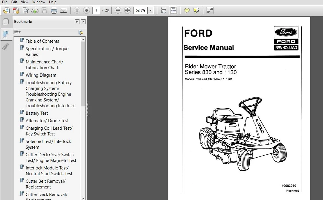
New Holland Rider Mower Tractor Series 830 & 1130 Service Repair Manual (40083010) – PDF Download
Original price was: $90.00.$39.95Current price is: $39.95.
New Holland Rider Mower Tractor Series 830 & 1130 Service Repair Manual
Part Number : (40083010)
Description
New Holland Rider Mower Tractor Series 830 & 1130 Service Repair Manual (40083010)
FILE DETAILS:
New Holland Rider Mower Tractor Series 830 & 1130 Service Repair Manual (40083010)
- New Holland Rider Mower Tractor 1130, 830 Service Manual_40083010
- Size: 6.26 MB
- Format: PDF
- Language: English
- Number of Pages: 28 pages
- Brand: New Holland
- Type of document: Service Manual
- Model: 1130, 830
- Part No: 40083010
NEW HOLLAND RIDER MOWER TRACTOR SERIES 830 & 1130 SERVICE REPAIR MANUAL (40083010) – PDF DOWNLOAD:
SCREENSHOTS OF THE MANUAL:
DESCRIPTION:
New Holland Rider Mower Tractor Series 830 & 1130 Service Repair Manual (40083010)
- Examine RH diiierential bearing for excesslve wear er damage. Examine LH ditferential bearing tor roughness or excessive internal clearance.
- Check nylon bushlng installed at axle and LH tube for excessive wear. inspect axle shaft and tube assembties for straightness. Examlne drive chain and differentiel sprocket forexcessive wear or damage. Clean and lubricate the drive chain. Damage or premature wear of diiferential sprocket teeth may be due to improper sprocket atignment.
- Remove the four shoulder Dolls, flat washers, and nuts securing the differentiai cover to the sprocket. Separate the sprocket from the cover housing. Account for the four shim washers installed between the pinion gears and the differential sprocket.
- Bear in mind that pinion gear and shim washers must be reassembled in the same sequence in order for the differentlal to function property. Examine the pinion gears far warn, chipped or missing teeth. Replace lt required. Heassemble and Install in reverse sequence.
- Check that both pairs of pinion gears are installed such that one pinion of each pair contacts the axle gear and the other contacts the gear mountad to the LH tube assembty. Place one drop of Loc- Tite 801 on the threads of each pinion mounting holt before installing the lack nuts. Check that ditterentlal cover aligns with the alignment tabs on the sprocket. Damage to the sprocket will result if the cover is improperly aligned. Heier to chain tension and sprocket alignment adjustments.
- DIFFERENTIAL AND TUBE ASSEMBLY REMOVAUREPLACEMENT
- Stand the unit upright and removetheflH and LH rear wheels. Disconnect the rear hanger counterbaiance spring and remove the bottom cover. Remove two capscrews‚ washers and nuts securing the Fit-t tube assembly to the axie shaft. Loosen the HH bearing strap and remove the RH diiferential bearing from side frame.
- Remove the RH tube assembly from the axle shaft. Account for the number and location oiany shim washers installed between tube and RH differential bearing and/or axle flange and Inside surface of RH side frame.
- These shims provide a means of alignlng diffemntial and reducer sprockets which prevents chain jumpan and premature sprocket failure.
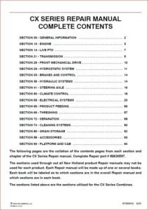
TABLE OF CONTENTS:
New Holland Rider Mower Tractor Series 830 & 1130 Service Repair Manual (40083010)
Table of Contents ………………………………………………………………………………………. 3
Specifications/ Torque Values ……………………………………………………………………………. 5
Maintenance Chart/ Lubrication Chart ……………………………………………………………………… 6
Wiring Diagram …………………………………………………………………………………………. 7
Troubleshooting Battery Charging System/ Troubleshooting Engine Cranking System/ Troubleshooting Interlock System …. 8
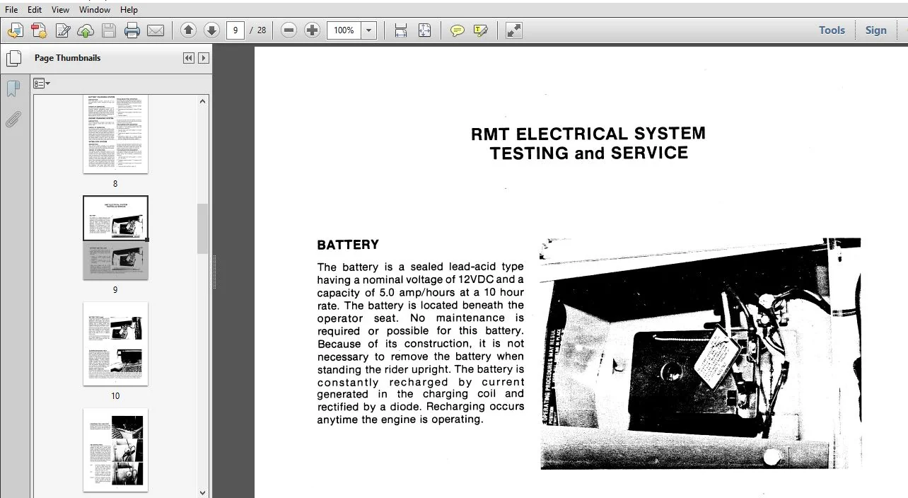
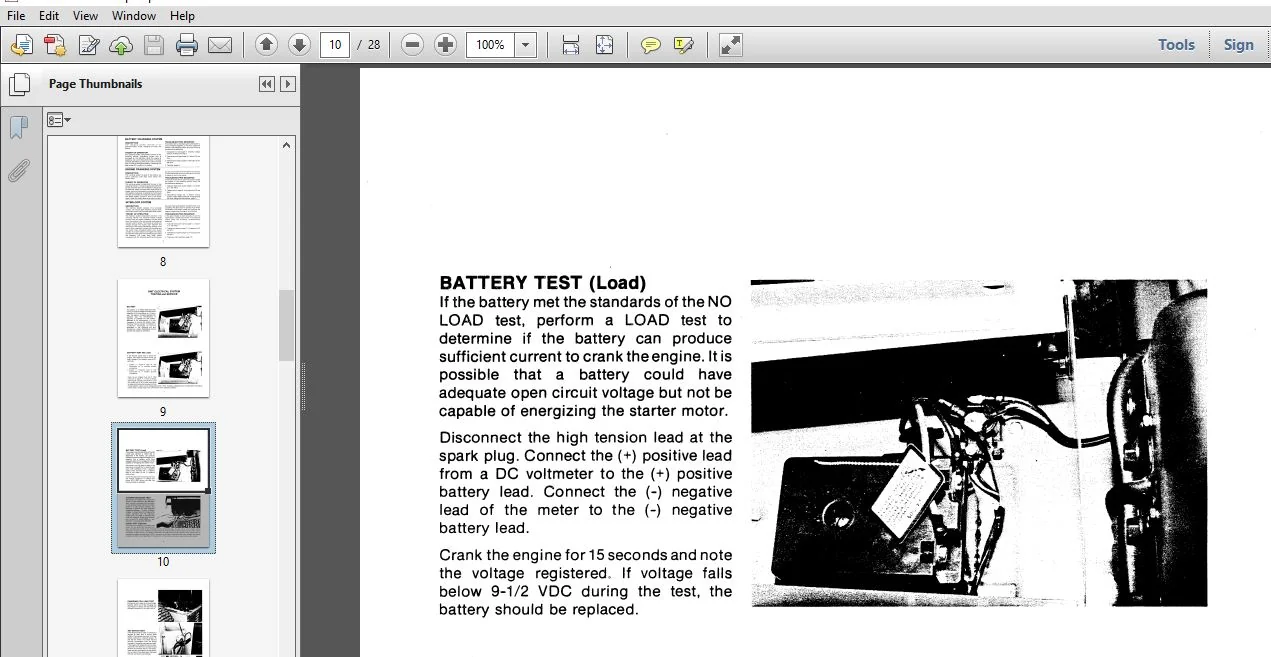
Battery Test …………………………………………………………………………………………… 9
Alternator/ Diode Test ………………………………………………………………………………….10
Charging Coil Lead Test/ Key Switch Test …………………………………………………………………..11
Solenoid Test/ Interlock System ………………………………………………………………………….12
Cutter Deck Cover Switch Test/ Engine Magneto Test ………………………………………………………..13
Interlock Module Test/ Neutral Start Switch Test ……………………………………………………………14
Cutter Belt Removal/ Replacement ………………………………………………………………………….15
Cutter Deck Removal/ Replacement ………………………………………………………………………….16
Cutter Deck Assembly Inspection/ Repair ……………………………………………………………………17
Frame, Steering, and Treadle Assembly Inspection/Repair Wheel/ Spindle Removal/ Replacement ……………………..18
Front Axle Removal/ Replacement …………………………………………………………………………..18
Steering Shaft, Lift Handle Assembly Removal/ Replacement/ Steering Sector/ Ball Bushing Removal/ Replacement …….19
Hex Shaft and Drive Wheel Removal, Replacement/ Hex Shaft and Drive Wheel Inspection, Repair ……………………20
Gear Reducer R Removal, Replacement/ Gear Reducer Inspection, Repair ………………………………………….21
Differential and Tube Assembly Removal/ Replacement ………………………………………………………..22
Differential and Tube Assembly Inspection/ Repair …………………………………………………………..23
Drive Disc and Pulley Removal, Replacement/ Drive Disc and Pulley Inspection, Repair ……………………………24
Differential Sprocket Alignment/ Drive Chain Tension Adjustment ………………………………………………25
Drive Wheel Clearance Adjustment ………………………………………………………………………….26
PLEASE NOTE:
- This is not a physical manual but a digital manual – meaning no physical copy will be couriered to you. The manual can be yours in the next 2 mins as once you make the payment, you will be directed to the download page IMMEDIATELY.
- This is the same manual used by the dealers inorder to diagnose your vehicle of its faults.
- Require some other service manual or have any queries: please WRITE to us at [email protected]