New Holland Rustler 120 125 Service Manual – PDF DOWNLOAD
Original price was: $68.95.$30.95Current price is: $30.95.
New Holland Rustler 120 125 Service Manual
Part No : CLC103700628
Description
New Holland Rustler 120 125 Service Manual
FILE DETAILS:
New Holland Rustler 120 125 Service Manual
Language : English
Pages : 436
Format : pdf
Downloadable : Yes
NEW HOLLAND RUSTLER 120 125 SERVICE MANUAL – PDF DOWNLOAD:
IMAGES PREVIEW OF THE MANUAL:
DESCRIPTION:
New Holland Rustler 120 125 Service Manual
FOREWORD:
These vehicles are designed and built to provide the ultimate in performance efficiency; however, proper maintenance and repair are essential for achieving maximum service life and continued safe and reliable operation. This manual provides detailed information for the maintenance and repair of New Holland Rustler™ 120 and 125 vehicles, and should be thoroughly reviewed prior to servicing the vehicles.
- The procedures provided must be properly implemented, and the DANGER, WARNING, and CAUTION statements must be heeded. This manual was written for the trained technician who already possesses knowledge and skills in electrical and mechanical repair. If the technician does not have such knowledge and skills, attempted service or repairs to the vehicle may render the vehicle unsafe.
- For this reason, the manufacturer advises that all repairs and/or service be performed by an authorized dealer representative or by a factory-trained technician. It is the policy of CNH America LLC to assist its distributors and dealers in continually updating their service knowledge and facilities so they can provide prompt and efficient service for vehicle owners.
- Regional technical representatives, vehicle service seminars, periodic service bulletins, maintenance and service manuals, and other service publications also represent continuing commitment to customer support.
- A full line of training and continuing education classes for technicians who want to learn more about our products. For more information, contact your local dealer or CNH America LLC for a list of upcoming classes.
- This manual covers all aspects of typical vehicle service; however, unique situations sometimes occur when servicing a vehicle. If it appears that a service question is not answered in this manual, please contact your nearest authorized dealer or distributor for assistance.
TABLE OF CONTENTS:
New Holland Rustler 120 125 Service Manual
SECTION 1 – SAFETY
Safety Details 1-1
General Warning 1-2
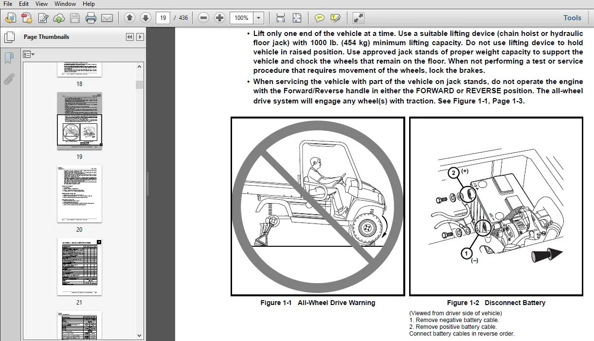
Disabling The Vehicle 1-4
Disconnecting The Battery 1-4
Connecting The Battery 1-4
SECTION 2 – VEHICLE SPECIFICATIONS
SECTION 3 – GENERAL INFORMATION
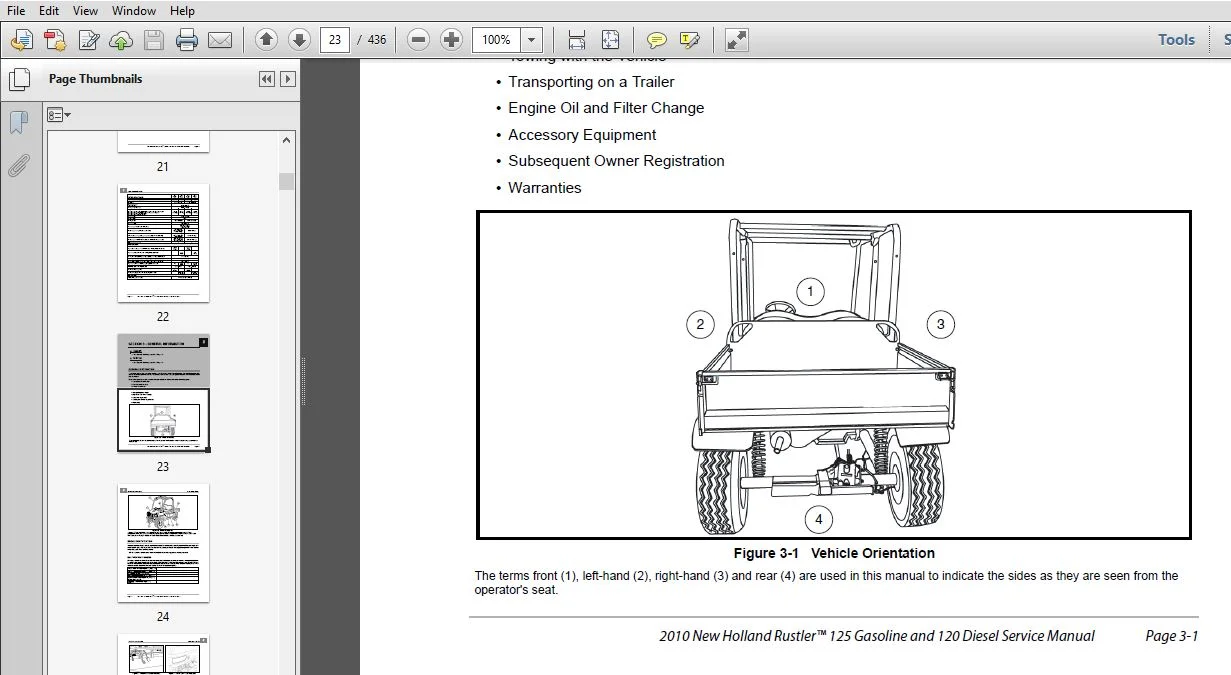
General Information 3-1
Model Identification 3-2
Identification Numbers 3-2
Storage 3-4
Preparing the Vehicle for Extended Storage 3-4
Returning the Stored Vehicle to Service 3-5
Using A Booster Battery (Jump Starting) 3-6
SECTION 4 – BODY AND TRIM
Cleaning the Vehicle 4-1
Seat Cleaning 4-1
Front Body Repair 4-2
Light Scratches 4-2
Abrasions and Haze 4-2
Large Scratches and Abrasions 4-2
Page iv 2010 New Holland Rustler™ 125 Gasoline and 120 Diesel Service Manual
Front Body Components 4-3
Instrument Panel Removal 4-3
Instrument Panel Installation 4-3
Front Fascia Removal 4-4
Front Fascia Installation 4-4
Hood Removal 4-4
Hood Installation 4-4
Center Cowl Panel Removal 4-4
Center Cowl Panel Installation 4-5
Side Cowl Panel (Fender) Removal 4-5
Side Cowl Panel (Fender) Installation 4-5
Front Fender Flare Removal 4-6
Front Fender Flare Installation 4-6
Roll-Over Protective Structure (ROPS) 4-6
ROPS Removal 4-6
ROPS Installation 4-8
Seat 4-9
Seat Removal 4-9
Seat Adjustment 4-9
Seat Installation 4-9
Seat Support Removal 4-10
Seat Support Installation 4-10
Safety Belts 4-10
Safety Belt Removal 4-10
Safety Belt Installation 4-11
Cargo Bed – Electric Lift 4-11
Testing the Bed Lift Motor 4-11
Bed Lift Motor Removal 4-11
Bed Lift Motor Installation 4-12
Cargo Bed Removal 4-12
Cargo Bed Installation 4-12
Cargo Bed – Manual Lift 4-13
Cargo Bed Removal 4-13
Cargo Bed Installation 4-13
Rear Fender 4-15
Rear Fender Removal 4-15
Rear Fender Installation 4-15
2010 New Holland Rustler™ 125 Gasoline and 120 Diesel Service Manual Page v
SECTION 5 – ACCELERATOR AND BRAKE PEDAL ASSEMBLIES
Accelerator Pedal 5-1
Accelerator Pedal Removal 5-1
Accelerator Pedal Installation 5-2
Accelerator Pedal and RPM Adjustment 5-2
Brake Pedal 5-3
Brake Pedal Removal 5-3
Brake Pedal Installation 5-3
Brake Pedal Adjustment 5-3
Park Brake Pedal 5-4
Park Brake Pedal Assembly Removal 5-4
Park Brake Pedal Assembly Installation 5-4
SECTION 6 – HYDRAULIC AND PARK BRAKE SYSTEMS
Brake System Inspection 6-1
Brake System Troubleshooting 6-3
Brake Pads and Caliper 6-6
Front Brake Pad and Caliper Removal 6-6
Front Brake Pad and Caliper Installation 6-7
Rear Brake Pad and Caliper Removal 6-8
Rear Brake Pad and Caliper Installation 6-9
Brake Disc and Hub 6-11
Front Wheel Disc and Hub Removal 6-11
Front Wheel Disc and Hub Installation 6-15
Rear Wheel Disc Removal 6-16
Rear Wheel Disc Installation 6-17
Hydraulic Line Replacement 6-18
Front Brake Line Removal 6-18
Front Brake Line Installation 6-18
Rear Brake Line Removal 6-19
Rear Brake Line Installation 6-20
Master Cylinder and Reservoir 6-21
Filling the Hydraulic System 6-21
Master Cylinder Removal 6-21
Master Cylinder Installation 6-22
Bleeding the Hydraulic Brake System 6-22
Bleeding Brakes on a DOT 5 Fluid Filled System 6-22
Purging the Hydraulic System 6-24
Page vi 2010 New Holland Rustler™ 125 Gasoline and 120 Diesel Service Manual
Park Brake System 6-25
Park Brake Adjustment – At Rear Calipers 6-25
Park Brake Cable Adjustment 6-25
Park Brake Wheel Cables 6-26
Front Park Brake Cable Removal 6-27
Front Park Brake Cable Installation 6-28
Park Brake Equalizer Removal 6-28
Park Brake Equalizer Installation 6-29
SECTION 7 – STEERING AND FRONT SUSPENSION
Steering Wheel 7-1
Steering Wheel Removal 7-1
Steering Wheel Installation 7-2
Steering Column 7-2
Steering Column Removal 7-2
Steering Column Installation 7-3
Rack and Pinion 7-3
Rack and Pinion Removal 7-3
Rack and Pinion Installation 7-4
Rack and Pinion Disassembly 7-5
Rack and Pinion Assembly 7-9
Front Suspension 7-11
Wheel Alignment 7-11
Front Suspension Components 7-13
Steering Upright Removal 7-13
Upper A-Arm Removal 7-14
Upper A-Arm Installation 7-16
Lower A-Arm Removal 7-16
Lower A-Arm Installation 7-17
Front Coil-Over Shock Absorber Removal 7-18
Front Coil-Over Shock Absorber Installation 7-19
Steering Upright Installation 7-19
SECTION 8 – WHEELS AND TIRES
General Information 8-1
Wheels 8-2
Wheel Removal 8-2
Wheel Installation 8-2
2010 New Holland Rustler™ 125 Gasoline and 120 Diesel Service Manual Page vii
Tires 8-2
Tire Removal 8-2
Tire Installation 8-3
SECTION 9 – REAR SUSPENSION
Rear Coil-Over Shock Absorber 9-1
Swing Arms 9-2
Swing Arm Removal 9-2
Swing Arm Installation 9-3
SECTION 10 – PERIODIC MAINTENANCE
Periodic Service Schedule 10-1
Periodic Lubrication Schedule 10-4
Brake Fluid Reservoir 10-6
Brake Fluid 10-6
Engine Oil 10-6
Oil Pressure – Gasoline Engine 10-7
Engine Oil Level Check 10-7
Engine Oil and Filter Change 10-7
Oil Viscosity 10-11
Spark Plugs 10-11
Spark Plug Cleaning And Inspection 10-11
Spark Plug Gap Inspection 10-11
Gearcase Lubrication 10-12
Lubrication Level Check for Front Differential, Transmission, and Rear Differential 10-12
Lubrication Change for Front Differential, Transmission, and Rear Differential 10-12
Engine Coolant – Diesel Vehicles 10-13
Engine Coolant Level Check 10-13
Fueling Instructions 10-14
Draining Water from Fuel Filter 10-15
Battery 10-16
SECTION 11A – TROUBLESHOOTING AND ELECTRICAL SYSTEM: GASOLINE VEHICLES
Troubleshooting Guide 11a-1
Wiring Diagram 11a-6
Test Procedures 11a-8
Index of Test Procedures 11a-8
Page viii 2010 New Holland Rustler™ 125 Gasoline and 120 Diesel Service Manual
SECTION 11B – TROUBLESHOOTING AND ELECTRICAL SYSTEM: DIESEL VEHICLES
Troubleshooting Guide 11b-1
Wiring Diagram 11b-6
Test Procedures 11b-8
Index of Test Procedures 11b-8
SECTION 12A – ELECTRICAL COMPONENTS: GASOLINE VEHICLES
Starter and Starter Solenoid 12a-1
Relays 12a-1
Neutral Switch 12a-2
Carburetor Solenoid 12a-2
Carburetor Heater 12a-3
Voltage Regulator 12a-4
Warning Lights 12a-5
Fuel Gauge/Hour Meter 12a-6
Key Switch 12a-7
12-Volt Accessory Receptacle 12a-8
Bed Lift Switch 12a-9
Bed Lift Circuit Breaker 12a-9
Light Switch 12a-10
Fuse 12a-10
Reverse Warning Buzzer (If Equipped) 12a-11
Reverse Warning Buzzer Limit Switch (If Equipped) 12a-12
Front Differential Limit Switch 12a-13
Fuel Level Sending Unit 12a-14
Ignition Coil and Charge Coil 12a-14
Oil Pressure Sensor 12a-15
Headlights 12a-15
Wire Harness Diodes 12a-16
Battery 12a-16
General Information 12a-17
SECTION 12B – ELECTRICAL COMPONENTS: DIESEL VEHICLES
Starter and Starter Solenoid 12b-1
Relays 12b-1
Neutral Switch 12b-2
Fuel Solenoid 12b-2
60-Amp Fusible Link 12b-3
2010 New Holland Rustler™ 125 Gasoline and 120 Diesel Service Manual Page ix
Warning Lights 12b-4
Fuel Gauge/Hour Meter 12b-6
Key Switch 12b-6
12-Volt Accessory Receptacle 12b-7
Bed Lift Switch 12b-8
Bed Lift Circuit Breaker 12b-8
Light Switch 12b-8
Fuse 12b-9
Reverse Warning Buzzer (If Equipped) 12b-10
Reverse Warning Buzzer Limit Switch (If Equipped) 12b-11
Front Differential Limit Switch 12b-12
Fuel Level Sending Unit 12b-13
Alternator 12b-13
Oil Pressure Sensor 12b-15
Headlights 12b-15
Thermostat Switch 12b-16
Fan 12b-18
Wire Harness Diodes 12b-19
Battery 12b-20
General Information 12b-20
SECTION 13A – GASOLINE ENGINE, MUFFLER, FUEL SYSTEM, AND CLUTCHES
Gasoline Engine 13a-1
Engine Removal 13a-1
Engine Installation 13a-3
Oil Filter Hoses 13a-5
Exhaust System 13a-6
Muffler Removal 13a-6
Intermediate Pipe Removal 13a-7
Intermediate Pipe Installation 13a-7
Muffler Installation 13a-8
Fuel System 13a-9
Fuel Lines 13a-9
Fuel Filter 13a-11
Fuel Pump 13a-11
Carburetor 13a-11
Fuel Level Sending Unit 13a-12
Fuel Tank 13a-16
Carbon Canister 13a-18
Fuel Shut-Off Valve 13a-20
Page x 2010 New Holland Rustler™ 125 Gasoline and 120 Diesel Service Manual
Engine Control Linkages 13a-21
Accelerator Cable 13a-21
Choke Cable 13a-23
Engine Governor Arm 13a-25
Engine RPM Adjustment 13a-25
Air Intake System 13a-26
Air Filter Replacement 13a-26
Air Canister Removal 13a-27
Air Canister Installation 13a-27
Air Filter Intake Hose Removal 13a-28
Air Filter Intake Hose Installation 13a-28
Air Filter Outlet Hose Removal 13a-29
Air Filter Outlet Hose Installation 13a-29
Clutches 13a-30
Clutch Troubleshooting 13a-30
Drive Belt 13a-31
Drive Clutch 13a-32
Driven Clutch 13a-37
Clutch Cover 13a-40
SECTION 13B – DIESEL ENGINE, MUFFLER, FUEL SYSTEM, AND CLUTCHES
Diesel Engine 13b-1
Engine Removal 13b-1
Engine Installation 13b-3
Exhaust System 13b-5
Muffler Removal 13b-5
Intermediate Pipe Removal 13b-5
Manifold Pipe Removal 13b-6
Manifold Pipe Installation 13b-6
Intermediate Pipe Installation 13b-6
Muffler Installation 13b-7
Fuel System 13b-8
Fuel Lines 13b-8
Bleeding Air From Fuel System 13b-9
Fuel Filter Replacement 13b-9
Fuel Pump 13b-11
Fuel Level Sending Unit 13b-11
Fuel Tank 13b-15
Engine Control Linkages 13b-18
Accelerator Cable 13b-18
Engine RPM Adjustment 13b-20
2010 New Holland Rustler™ 125 Gasoline and 120 Diesel Service Manual Page xi
Air Intake System 13b-22
Air Filter Replacement 13b-22
Air Canister Removal 13b-23
Air Canister Installation 13b-24
Air Filter Intake Hose Removal 13b-24
Air Filter Intake Hose Installation 13b-25
Air Filter Outlet Hose Removal 13b-25
Air Filter Outlet Hose Installation 13b-25
Clutches 13b-26
Clutch Troubleshooting 13b-26
Drive Belt 13b-27
Drive Clutch 13b-28
Driven Clutch 13b-32
Clutch Cover 13b-34
SECTION 14 – DRIVETRAIN COMPONENTS
Half Shafts 14-1
Half Shaft Removal 14-1
Half Shaft Installation 14-3
Front Differential 14-4
Front Differential Removal 14-4
Front Differential Installation 14-6
Front Driveshaft 14-6
Front Driveshaft Removal 14-6
Front Driveshaft Installation 14-7
Rear Receiver Hitch 14-7
Rear Receiver Hitch Removal 14-7
Rear Receiver Hitch Installation 14-7
Rear Axle 14-8
Rear Axle Removal 14-8
Rear Axle Installation 14-10
Rear Driveshaft 14-11
Rear Driveshaft Removal 14-11
Rear Driveshaft Installation 14-12
Transmission 14-12
Transmission Removal 14-12
Transmission Installation 14-14
Forward/Reverse Shifter Cable 14-15
Forward/Reverse Shifter Handle 14-18
Page xii 2010 New Holland Rustler™ 125 Gasoline and 120 Diesel Service Manual
Rear Differential and Axle Shafts 14-18
Rear Differential and Axle Shaft Removal 14-18
Rear Differential and Axle Shaft Installation 14-20
Rear Wheel Bearings 14-20
SECTION 15 – RADIATOR AND COOLANT SYSTEM (DIESEL)
General Information 15-1
Engine Coolant Level Check 15-1
Engine Coolant Change 15-1
Coolant Reservoir 15-3
Coolant Reservoir Removal 15-3
Coolant Reservoir Installation 15-4
Radiator 15-4
Radiator Removal 15-4
Radiator Installation 15-5
Coolant Pipe Weldment 15-6
Coolant Pipe Weldment Removal 15-6
Coolant Pipe Weldment Installation 15-6
Fan 15-7
Fan Removal 15-7
Fan Installation 15-7
SECTION 16 – TRANSMISSION
General Information 16-1
Service Fixture 16-1
Transmission Removal 16-2
Transmission Disassembly 16-2
Input Shaft Disassembly 16-8
Input Shaft Assembly 16-8
Intermediate Shaft Disassembly 16-8
Output Shaft Disassembly 16-12
Shifter Shaft Removal 16-13
Shifter Shaft Installation 16-14
Case Inspection 16-14
Shaft Seal Removal 16-15
Shaft Seal Installation 16-15
Output Shaft Assembly 16-15
Intermediate Shaft Assembly 16-18
Intermediate and Output Shaft Assembly 16-22
Transmission Assembly 16-23
2010 New Holland Rustler™ 125 Gasoline and 120 Diesel Service Manual Page xiii
Transmission Installation 16-27
SECTION 17 – FRONT DIFFERENTIAL
General Information 17-1
Axle Half Shaft Removal 17-1
Front Differential Removal 17-2
Tools Required For This Section 17-3
Front Differential Coil And Output Cover 17-3
Coil and Output Cover Removal 17-3
Coil and Output Cover Installation 17-6
Front Differential 17-8
Front Differential Disassembly 17-8
Front Differential Assembly 17-14
Front Differential Installation 17-18
Axle Half Shaft Installation 17-18
SECTION 18 – REAR DIFFERENTIAL
General Information 18-1
Axle Shafts and Differential Removal 18-2
Rear Differential Disassembly 18-2
Pinion Gear Removal 18-4
Ring Gear Removal 18-6
Clutch Carrier 18-7
Clutch Components 18-7
Ring Gear Installation 18-9
Pinion Gear Installation 18-9
Rear Differential Assembly 18-10
Axle Shafts and Differential Installation 18-11
SECTION i – INDEX
PLEASE NOTE:
- This is the SAME exact manual used by your dealers to fix your vehicle.
- The same can be yours in the next 2-3 mins as you will be directed to the download page immediately after paying for the manual.
- Any queries / doubts regarding your purchase, please feel free to contact [email protected]